1999 HONDA CIVIC Counter shaft
[x] Cancel search: Counter shaftPage 790 of 2189

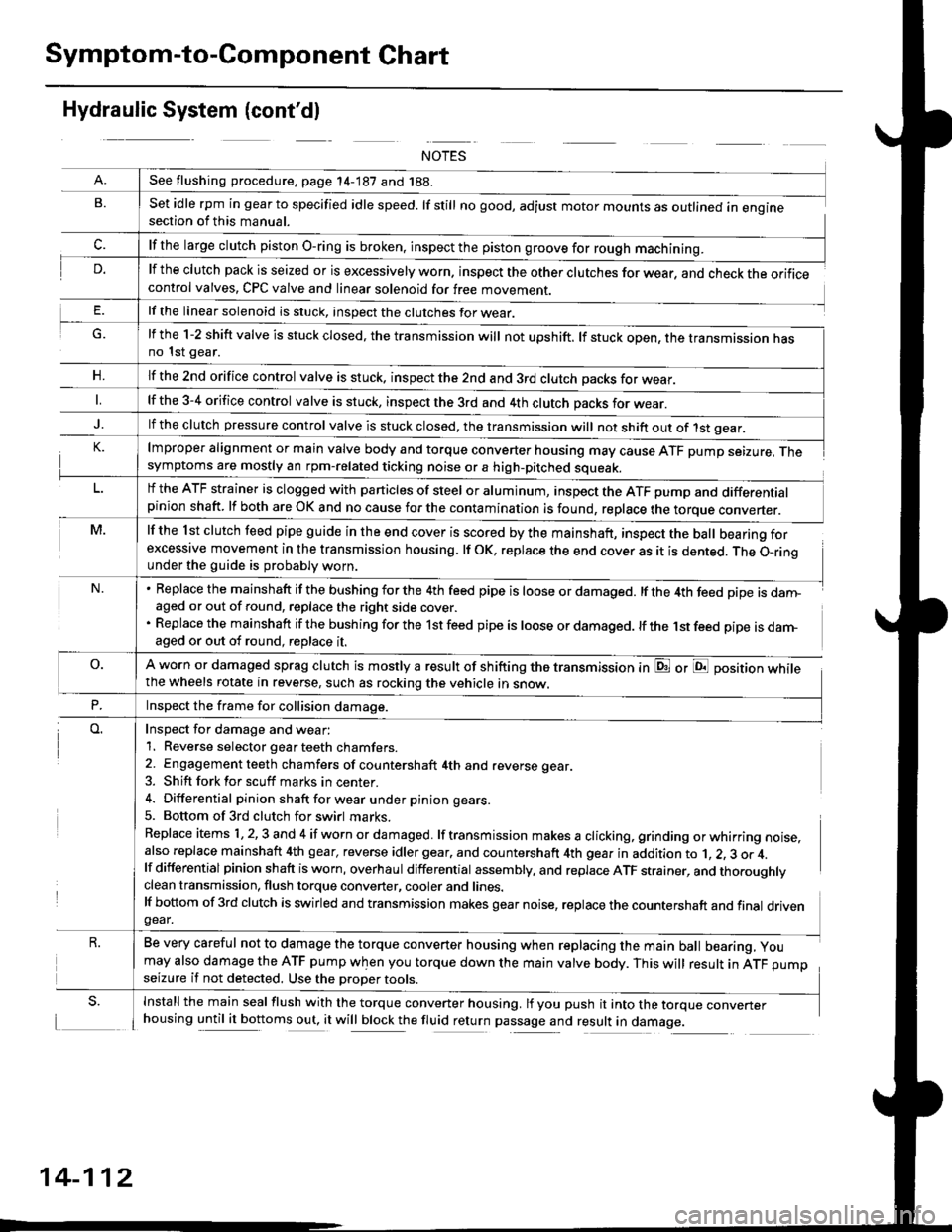
Symptom-to-Component Chart
Hydraulic System (cont'dl
G.
n,
set idle rpm in gear to specified idle speed. lf still no good, adjust motor mounts as outlined in enginesection of this manual.
lf the clutch pack is seized or is excessively worn. inspect the other clutches for wear, and check the orificecontrol valves, CPC valve and linear solenoid for free movement.
lf the linear solenoid is stuck, inspect the clutches for wear.
lmproper alignment or main valve body and torque converter housing may cause ATF pump seizure. Thesymptoms are mostly an rpm-related ticking noise or a high-pitched squeak.
lf the l st clutch feed pipe guide in the end cover is scored by the mainshaft, inspect the ball bearing forexcessive movement in the transmission housing. lf oK, replace the end cover as it is dented. The o-rinounder the guide is probably worn.
Replace the mainshaft if the bushing for the 4th feed pipe is loose or damaged. lf the 4th feed pipe is danFaged or out of round, replace the right side cover.
Replace the mainshaft if the bushing for the 1st feed pipe is loose or damaged. lf the 1st feed pipe is darn-aged or out of round, replace it.
A worn or damaged sprag clutch is mostly a result of shifting the transmission inthe wheels rotate in reverse, such as rocking the vehicle in snow.
or E position while
Inspect for damage and wear:
1. Reverse selector gear teeth chamfers.
2. Engagement teeth chamfers of countershaft 4th and reverse gear.
3. Shift fork for scuff marks in center.
4. Differential pinion shaft for wear u nder pin ion gears.
5. Bottom of 3rd clutch for swirl marks.
Replace items 1,2,3 and 4 if worn or damaged. lf transmission makes a clicking, grinding orwhirring noise,also replace mainshaft 4th gear, reverse idler gear. and countershaft 4th gear in addition to 1, 2, 3 or 4.lf differential pinion shaft is worn, overhaul differential assembly, and replace ATF strainer, and thoroughlyclean transmission, flush torque converter, cooler and lines.lf bottom of 3rd clutch is swirled and transmission makes gear noise, replace the countershaft and final drivengear.
Be very careful not to damage the torque converter housing when replacing the main ball bearing, you
may also damage the ATF pump when you torque down the main valve body. This will result in ATF pumpseizure if not detected. Use the oroper roors.
Install the main seal flush with the torque converter housing. lf you push it into the torque converterhousing until it bottoms out, it will block the fluid return passage and result in damage.
See flushing procedure, page 14-187 and 188.
lf the large clutch piston O-ring is broken, inspect the piston groove for rough machining.
lf the l-2 shift valve is stuck closed, the transmission will not upshift. lf stuck open, the transmission hasno 1st gear.
lf the znd orifice control valve is stuck. inspect the 2nd and 3rd clutch oacks for wear.
lf the 3-4 orifice control valve is stuck, inspect the 3rd and 4th clutch oacks for wear.
lf the clutch pressure control valve is stuck closed, the transmission will not shift out of 1st gear.
lf the ATF strainer is clogged with particles of steel or aluminum, inspect the ATF pump and differentialpinion shaft. lf both are OK and no cause for the contamination is found, replace the torque converter.
Inspect the frame for collision damage.
14-112
Page 800 of 2189

Transmission
Removal
@Maks sure lifts, iacks and safety stands are placedproperly, and hoist bracket ate aftached to the cor_rec{ position on the engine lsee section 1).Apply parking brake and block rear whoels so vehiclewill not roll off stands and fall on you while workingunder it.
CAUTION: Use tender covers to avoid damaging paint-ed surfaces.
1, Disconnect the battery negative (_) terminal fromthe battery, then remove the positive (+) terminal.
2. Remove the intake air duct.
D16Y7 engins:
Remove the intake air duct and resonator.
D16Y8 engine:
Remove the intake air duct and the air cleaner hous-ing assembly,
3. Remove the starter cables and cable holder fromthe starter motor.
MOTOR CABLE
MOTOR CABLE
14-122
4. Remove the transmission ground cable, and discon_nect the lock-up control solenoid connector.
LOCK.UP CONTROLSOLENOID CONNECTOR
5, Disconnect the vehicle speed sensor (VSS) connec_tor and the countershaft speed sensor connector.
VEHICLE SPEED
Page 805 of 2189

O ROLLER
O COLLAR
O o-RING Replace.
@ FEED PIPE FLANGE
@ O-RING Replace.
@ SNAP RING
€) 3RD CLUTCH FEED PIPE
€) COUNTERSHAFT LOCKNUT (FLANGE NUT)
23 x 1.25 mm Replace.
o coNlcAL SPRING WASHER Replace.
@ PARK GEAR
@ ONE.WAY CLUTCH
@ COUNTERSHAFT lST GEAR
@ NEEDLE BEARING
@ COUNTERSHAFT lST GEAR COLLAR
@ o-RlNGs Replace.
@ END covER GASKET Replace.
E) DOWEL PINS
@ PARK PAWL STOP
@ LocK WASHER Replace.
@ PARK STOP Selective part
€D PARK LEVER
@ PARK LEVER SPRING
€D DRAIN PLUG
€) SEALING WASHER Replace
@ o-RING Replace.
@ COUNTERSHAFT SPEED SENSOR
@) PARK PAWL
@ PARK PAWL SPRING
@ PARK PAWL SHAFT
@ LINEAR SOLENOID ASSEMBLY
@ LINEAR SOLENOID GASKET REPIACE.
@) END COVER
@ lsT CLUTCH FEED PIPE
@ O-RINGS Replace.
@ FEED PIPE FLANGE
C) SNAP BING
@ MAINSHAFT LOCKNUT (FLANGE NUTI 21 x 1 25 mm
Replace.
@ CONICAL SPRING WASHER RePlace
@) lST CLUTCH ASSEMBLY
@ o-RlNGs Replace.
€) THRUST WASHER
@) THRUST NEEDLE BEARING
@ NEEDLE BEARING
@ MAINSHAFT lST GEAR
@ MAINSHAFT lST GEAR COLLAR
@) ATF COOLER LINE
@ SEAUNG WASHERS Replace.
@ LINE BOLT
@ ATF DIFSTICK
@ ATF COOLER LINE
@ UNE BOLT
@ SEALING WASHERS Replace.
@ VEHICTT SPEED SENSOR
@ O-RING Replace.
TOROUE SPECIFICATIONS
Bolt/Nut No.Torque ValueSizeRemarks
6B
8F
12A.'l8D
2'tM
23C
'12 N'm (1.2 kgim,8.7 lbift)
14 N.m (1.4 kgf.m, 10 lbf'ft)
22 N.m (2.2 kgf.m, 16 lbf'ft)
28 N.m (2.9 kgf.m, 21 lbf'ft)
49 N.m (5.0 kgf.m, 36 lbf'ft)
78 N.m (8.0 kgf'm, 58 lbf'ft)
103 N.m {10.5 kgf'm,75.9 lbift)
6x1.0mm
6x1.0mm
8 x 1,25 mm
12 x 1.25 mm
18 x 1.5 mm
21 x 1.25 mm
23 x 1.25 mm
Line bolt
Drain plug
Mainshatt locknut: Left-hand threads
Countershaft locknut:
Left-hand threads
14-127
Page 807 of 2189

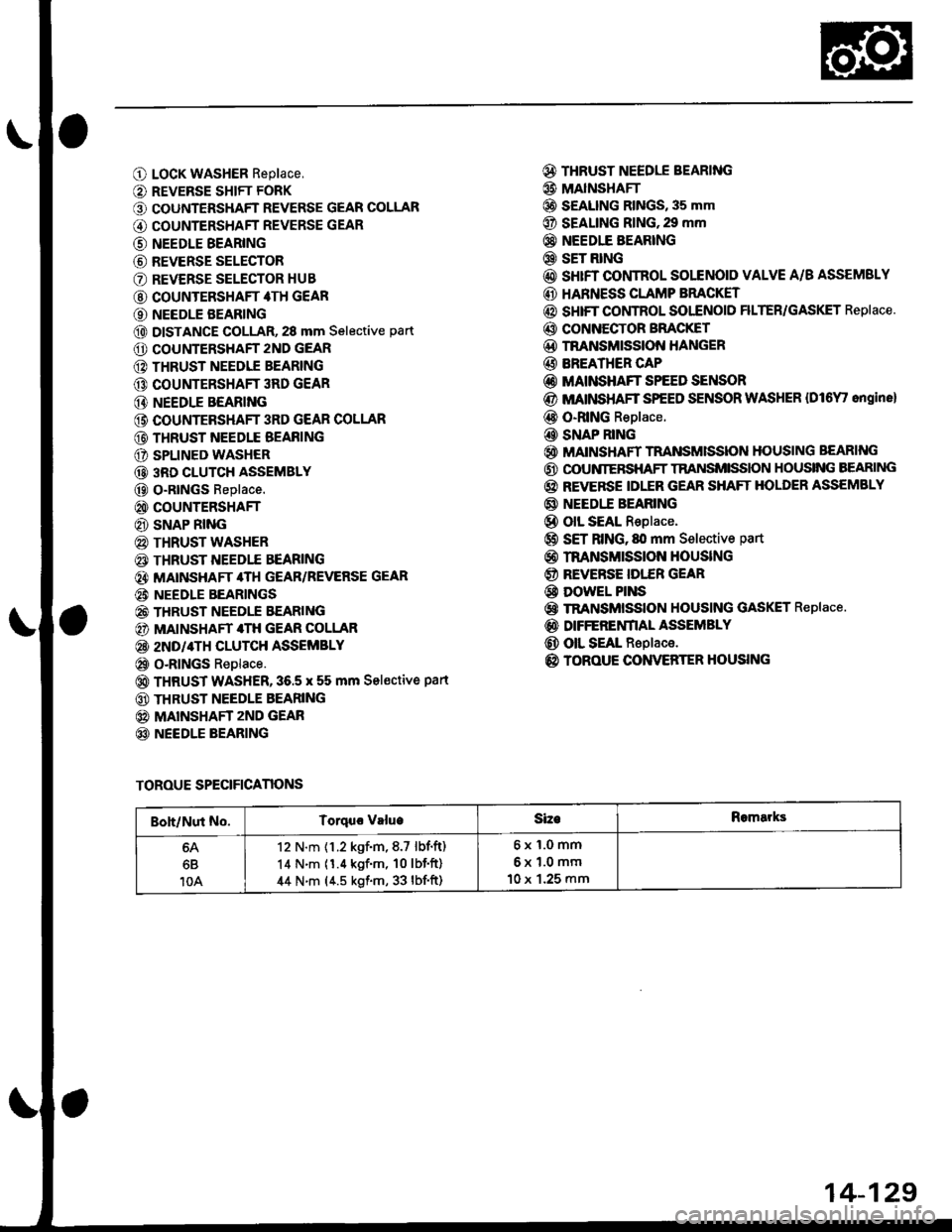
O LocK WASHER Replace,
O REVERSE SHIFT FORK
O COUNTERSHAFT REVERSE GEAR COLLAR
G) COUNTERSHAFT REVERSE GEAR
@ NEEDLE BEARING
@ REVERSE SELECTOR
O REVERSE SELECTOR HUB
@ COUNTERSHAFT 4TH GEAR
O NEEDLE BEARING
@ DISTANCE GOLLAR, 28 mm Selective part
O COUNTERSHAFT 2ND GEAR
@ THRUST NEEDIE BEARING
@ COUNTERSHAFT 3RD GEAR
@ NEEDLE BEARING
@ COUNTEBSHAFT 3RD GEAR COLLAR
@ THRUST NEEDLE BEAFING
O SPLINED WASHER
@ 3RD CLUTCH ASSEMBLY
@ O-RtNGs Replace.
@ COUNTERSHAFT
@ SNAP RING
@ THRUST WASHER
€) THRUST NEEDTE BEARING
@} MATNSHAFT 4TH GEAR/REVERSE GEAR
@i NEEDLE BEARINGS
@ THRUST NEEDLE EEARING
@) MAINSHAFT 4TH GEAR COLLAR
@ 2ND/4TH CLUTCH ASSEMBLY
@ o-RlNGs Replace.
@ THRUST WASHER,36.5 x 55 mm Sel€ctive part
@ THRUST NEEDLE BEARING
@ MAINSHAFT zND GEAR
@ NEEDLE BEARING
@ THRUST NEEDLE BEARING
@ MAINSHAFI
@ S€ALING RINGS, 35 mm
@ SEALING RING,29 mm
@} NEEDIE BEARING
@ SET RING
@ sHrFT CONTROL SOLENOID VALVE A/B ASSEMSLY
@ HARNESS CLAMP BRACKET
@ SHIFT COI,ITROL SOI"ENOID FILTER/GASKET Replace.
@ CONNECTOR BFACKET
@D TNANSMISSION HANGER
@ BREATHER CAP
@ MAINSHAFT SPEED SENSOR
@ MATNSHAFT SPEED SENSOR WASHER {Dl6Y' ongine}
@ O-RING Replace.
@ SNAP RING
@ MAINSHAFT TRANSMISSION HOUSING BEARING
@ OOUNIERSHAFT TRANSMISSION HOUSING BEARING
@ REVERSE IDLER GEAR SHAFT HOLDER ASSEMBLY
@ NEEDI.E BEARING
@ olL SEAL Replace.
@ SET RING, fll mm Selective part
@ rnANsMrssloN HouslNG
@ REVERSE IDI."ER GEAR
@ DowEL PINS
@ TRANSMISSION HOUSING GASKET Replace.
@ DIFFERENfIAL ASSEMBLY
@ OIL SEAL Replace.
@ TOROUE CONVERTER HOUSING
TOROUE SPECIFICANONS
Boh/Nut No.Torquo valueSizeRomarks
6B
10A
12 N.m {1.2 kgf.m,8.7 lbf.ft)
14 N.m (1.4 kgf'm, 10lbf'ft)
44 N.m (4.5 kgf.m, 33 lbf'ft)
6x1.0mm
6x1.0mm
10 x 1.25 mm
14-129
Page 809 of 2189

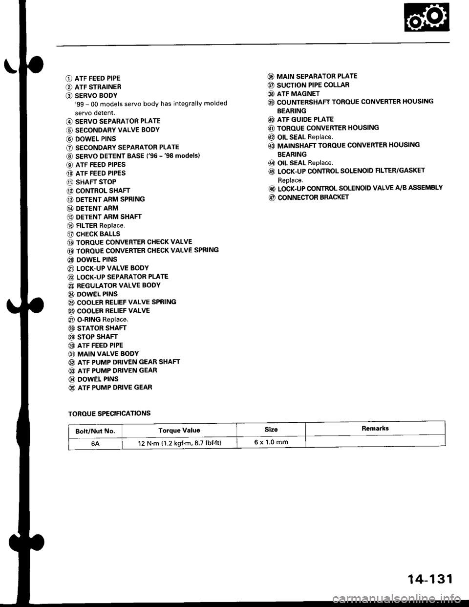
O ATF FEED PIPE
O ATF STRAINER
O SERVO BODY'99 - 00 models servo body has integrally molded
servo detent.
@ SERVO SEPARATOR PLATE
(' SECONDARY VALVE BODY
@ DOWEL P|NS
O SECONDARY SEPARATOR PLATE
@ SERVO DETENT BASE ('�96 -'98 models)
O ATF FEED PIPES
(D ATF FEED PIPES
O SHAFT STOP
@ CONTROL SHAFT
€D DETENT ARM SPRING
@ DETENT ARM
(9 DETENT ARM SHAFT
@ FILTER Replace.
(? CHECK BALLS
@ TOROUE CONVERTER CHECK VALVE
@ TOROUE CONVERTER CHECK VALVE SPRING
@ DOWEL PINS
@ LOCK.UP VALVE BODY
@ LOCK-UP SEPARATOR PLATE
@ REGULATOR VALVE BODY
@} DOWEL PINS
@ COOLER RELIEF VALVE SPRING
@ COOLER RELIEF VALVE
@ O-RING Replace.
@ STATOR SHAFT
@ STOP SHAFT
@ ATF FEED PIPE
@ MAIN VALVE BODY
@ ATF PUMP DRIVEN GEAR SHAFT
@ ATF PUMP DRIVEN GEAR
@ DOWEL PINS
65) ATF PUMP DRIVE GEAR
@ MAIN SEPARATOR PLATE
@ SUCTION PIPE COLLAR
@ ATF MAGNET
@ COUNTERSHAFT TOROUE CONVERTER HOUSING
BEARING
@ ATF GUIDE PLATE
@ ToRoUE CONVERTER HOUSING
@ OIL SEAL Replace.
@ MAINSHAFT TOROUE CONVERTER HOUSING
BEARING
@) olL SEAL Replace.
@ LOCK-UP CONTROL SOLENOID FILTER/GASKET
Reolace.
@ LOCK-UP CONIROL SOLENOID VALVE A/B ASSEMELY
@ CONNECTOR BRACKET
TOROUE SPECIFICANONS
Bolt/Nut No.Torque ValugSiz€Remarkg
12 N.m (1.2 kgf.m,8.7 lbnft)6x1,0mm
14-131
Page 810 of 2189

End Cover
Removal
NOTE:
. Cleanall parts thoroughly in solvent or carburetor cleaner, and drywith compressed air,. Blow out all passages,
. When removing the right side cover, replace the following:- O-rings- Mainshaft and countershaft locknuts- Conical spring washgrs- End cover gasket
- Lock washer- Sealing washers
END COVER6 x 1.0 mm BOLT13 Bolts
PARK PAWL
PARK ITVER
LOCK WASHER
COUI{TERSI{AFTLINE AOLT
tST GEAF COLLAR
I
14-132
SEALING WASHERS
Page 811 of 2189

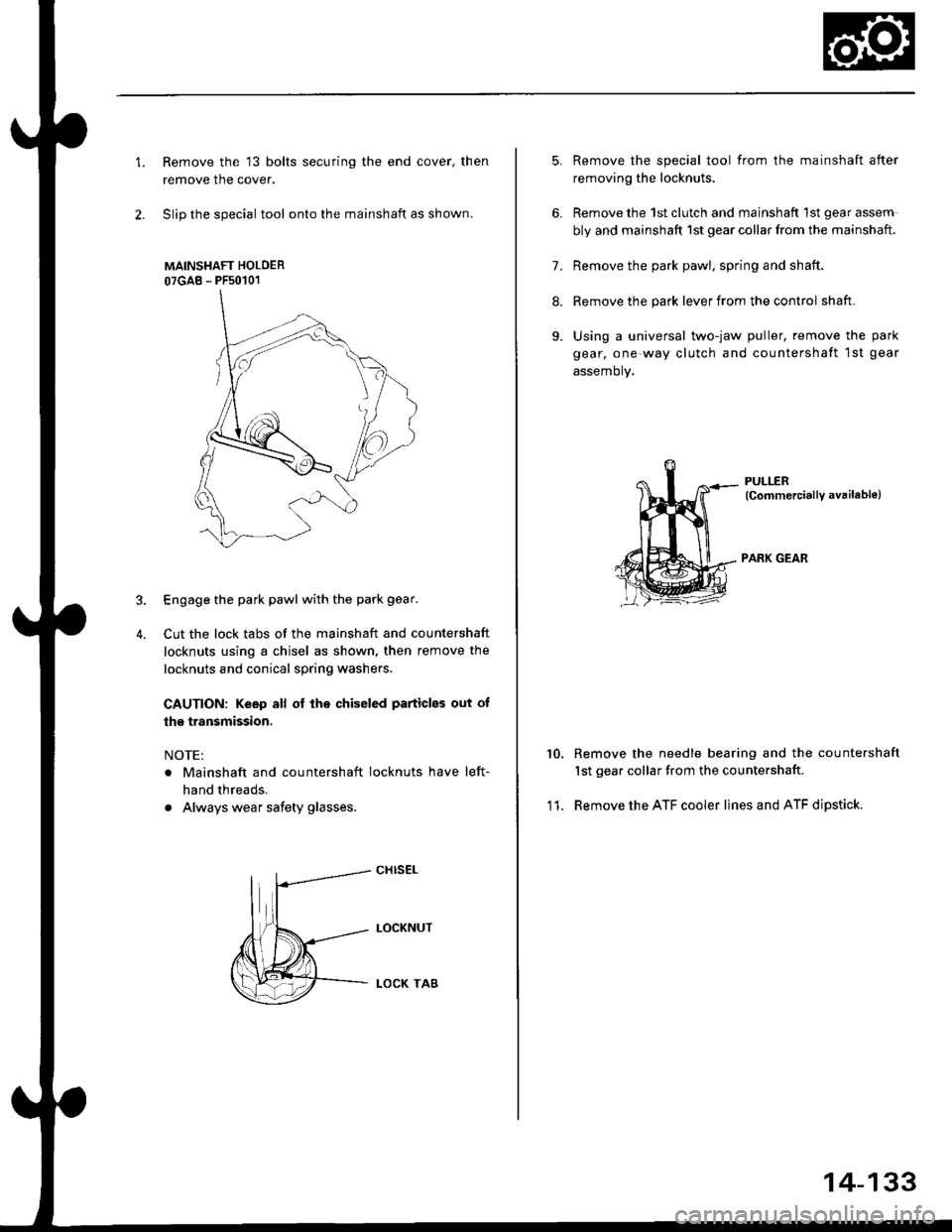
1.Remove the 13 bolts securing the end cover, then
remove the cover.
Slip the special tool onto the mainshaft as shown.
MAINSHAFT HOLOER
07GAB - PFs0101
Engage the park pawl with the park gear.
Cut the lock tabs of the mainshaft and countershaft
locknuts using a chisel as shown. then remove the
locknuts and conical spring washers
CAUTION: Keep all of lhe chiseled particles out of
the transmission.
NOTE:
. Mainshaft and countershaft locknuts have left-
hand threads.
. Always wear safety glasses.
4.
cHrs€L
LOCKNUT
LOCK TA8
5.
6.
11.
Remove the special tool from the mainshaft after
removing the locknuts.
Remove the 1st clutch and mainshaft 1st gear assem
bly and mainshaft 1st gear collar from the mainshaft.
7. Remove the park pawl. spring and shaft.
8. Remove the park lever from the control shaft.
9. Using a universal two-jaw puller, remove the park
gear, one way clutch and countershaft 1st gear
assemory.
PULLER(CommerciallY available)
PARK GEAR
10.Remove the needle bearing and the countershaft
1st gear collar from the countershaft
Remove the ATF cooler lines and ATF dipstick.
14-133
Page 829 of 2189

Countershaft
Disassembly/lnspection/Reassembly
NOTE:
. Lubricate all parts with ATF before reassembly'
. tnrp"",,n",t -"t needle bearings and the needle bearings for galling and rough movement'
. Before installing the O-rings. wrap the shaft splines with tape to prevent damaging the O-rings
. Locknut has left-hand threads
LOCKNUT (FLANGE NUT}
23 x 1.25 mm103 N.m
{10.5 kgf'm, 75.9 lbf'tt)
Replace.Left'handlhreads
CONTCAL SPRING
WASHERReplace.
GEAR
CLUTCH
1ST GEAR
BEARING
lST GEAR COLLAR
TRANSMISSIONHOUSING BEARING
REVERSE GEAR
NEEDLEBEARING
SELECTOR
SELECTOR
4TH GEAR
NEEDLE BEARING
DISTANCE COLLAS,
28 mmSelective pa .
COUNYERSHAFTCheck splines lor excesslve
wear and damage
2'{D GEAR
THRUST NEEDLEBEARING
3RD GEAB
NEEDLE BEARING
3RD GEAR COLLAR
THRUST NEEDLE EEARING
SPLINEO WASHER
3RD CLUTCH ASSEMBLY
Check bearing surface for scoring'
scratches and excessive wear'
Replace.
1+151