1999 FORD WINDSTAR battery
[x] Cancel search: batteryPage 6 of 248

WARNING LIGHTS AND CHIMES
Low fuel
Illuminates as an early reminder of a
low fuel condition indicated on the
fuel gauge. The light comes on when
there is approximately 1/16th of a
tank indicated on the fuel gauge
(refer toFuel gaugein this chapter
for more information). The ignition must be in the ON position for this
lamp to illuminate. The lamp will also illuminate for several seconds after
the ignition is turned to the ON position regardless of the fuel level.
Charging system
Illuminates when the ignition is
turned to the ON position and the
engine is off. The light also
illuminates when the battery is not
charging properly, requiring
electrical system service.
Traction ControlYactive (if equipped)
This light momentarily illuminates
when the ignition is turned to ON. It
also illuminates when the Traction
Controlysystem begins applying and
releasing the brakes and adjusting the
engine characteristics to limit a
wheelspin condition. It will be lit for a minimum of four seconds or for the
duration of the Traction Controlyevent.
For more information, refer to theDrivingchapter.
40
4080
120
160
20020
12345
6
760
80100
120MPH RPMX1000 THEFT
TRAC
ACTIVE TRAC
OFFTEMP
H
FFUEL
E
km/h
BRAKE
mi
O/D
OFF
TRAC
ACTIVE
Instrumentation
6
Page 26 of 248

Battery saver
The battery saver will shut off the exterior lamps 10 minutes after the
ignition switch has been turned off and the headlamp control is in the
HEADLAMP position. The system will not turn off the parking lamps if
the headlamp control is in the PARK position. For interior lights, refer to
Illuminated entryin this chapter.
Daytime running lamps (DRL) (if equipped)
Turns the highbeam headlamps on with a reduced output. To activate:
²the key must be in the ON position,
²the headlamp control is in the OFF or Parking lamps position.
Always remember to turn on your headlamps at dusk or during
inclement weather. The Daytime Running Light (DRL) System
does not activate your tail lamps and generally may not provide
adequate lighting during these conditions. Failure to activate your
headlamps under these conditions may result in a collision.
High beams
Push forward to activate.
Flash to pass
Pull toward you to activate and
release to deactivate.
Controls and features
26
Page 89 of 248

Closing the PSD
With the ON/OFF control in the ON position, either sliding door can be
closed by:
²operating the remote transmitter. Refer toRemote Entry Systemin
this chapter.
²pushing and releasing the overhead console right hand or left hand
control
²pushing and releasing the right hand or left hand second row
passenger control
²manually rolling the door several inches towards the closed position
and release
The door will close completely and latch using these options.
With the ON/OFF control in the OFF position, either sliding door can be
closed by pulling the inside or outside handle and sliding the door all the
way forward to the latched position manually.
Safety/Obstructions
If anything obstructs the Power Sliding Door while it is closing, the door
will automatically reverse to the open position, provided it meets
sufficient resistance.
Resetting the PSD
The power sliding door may operate incorrectly or not at all because of
the following condition:
²a low voltage or dead battery
²disconnecting the battery
²if the PSD fuse (fuse #6) is removed or blown. Refer toFuses and
relaysin theRoadside emergencieschapter.
If any of these conditions occur, reset the PSD by:
1. Check to see if power sliding door is unlocked and securely closed.
2. Make sure vehicle is in (P) Park.
3. Push the power door control on the overhead console to open the
door.
4. Wait five (5) seconds and close the door by pressing the power door
control on the overhead console.
5. Wait five (5) seconds and repeat Steps 3 and 4 and go on to step 6.
Controls and features
89
Page 96 of 248

This device complies with part 15 of the FCC rules and with RS-210 of
Industry Canada. Operation is subject to the following two conditions:
(1) This device may not cause harmful interference, and (2) This device
must accept any interference received, including interference that may
cause undesired operation.
Changes or modifications not expressly approved by the party
responsible for compliance could void the user's authority to
operate the equipment.
Illuminated entry
The interior lights will illuminate when the remote entry Unlock or Panic
control is pressed with the doors closed or when unlocking or opening a
power sliding door (if equipped).
The system automatically turns off after 25 seconds or when the ignition
is turned to the RUN position. The panel dimmer control mustnotbe
set to the OFF position for the illuminated entry to operate.
The inside lights will not turn off if:
²they have been turned on with the instrument panel dimmer control
or
²any door is open.
The battery saver will shut off the interior lamps 30 minutes after the
last door is closed even if the panel dimmer control is left on.
Illuminated exit
The interior lights will illuminate when the key is removed from the
ignition. When the headlamp control is on the ªsleeping baby modeº, only
the lower interior lights will illuminate.
The system automatically turns off after 25 seconds or when the driver's
door is opened. The panel dimmer control mustnotbe set to the OFF
position for the illuminated entry to operate.
Controls and features
96
Page 97 of 248

Replacing the battery
The transmitter is powered by one coin type three-volt lithium battery
CR2032 or equivalent. Typical operating range will allow you to be up to
10 meters (33 feet) away from your vehicle. A decrease in operating
range can be caused by:
²weather conditions
²nearby radio towers
²structures around the vehicle
²other vehicles parked next to the vehicle
To replace the battery:
1. Twist a thin coin between the two
halves of the transmitter near the
key ring. DO NOT TAKE THE
FRONT PART OF THE
TRANSMITTER APART.
2. Place the positive (+) side of new
battery in the same orientation.
Refer to the diagram inside the
transmitter unit.
3. Snap the two halves back
together.
Replacement of the battery willnotcause the remote transmitter to
become deprogrammed from your vehicle. The remote transmitter should
operate normally after battery replacement.
Controls and features
97
Page 156 of 248

Driving with an automatic overdrive transaxle with column
gearshift and O/D off switch
Your automatic transaxle electronically controls the shift feel by using an
adaptive learning strategy. This feature is designed to optimize shift
smoothness. It is normal for your transaxle to shift abruptly during the
first few hundred kilometers (miles) of operation until the adaptive
strategy has been learned. The adaptive learning strategy is maintained
by power from the battery. When the battery is disconnected or a new
battery is installed, the transaxle must relearn its adaptive strategy.
Optimal shifting will resume within a few hundred kilometers (miles) of
operation.
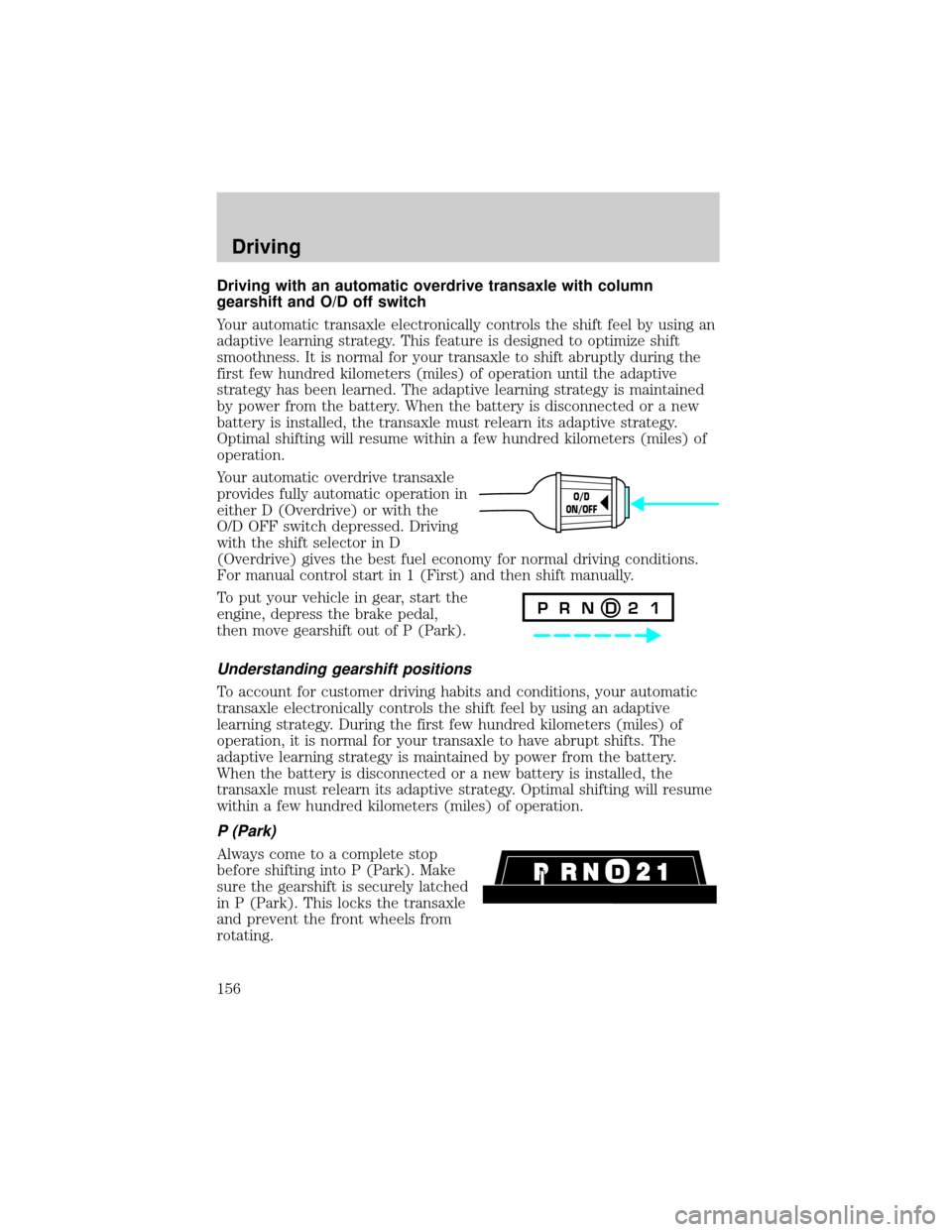
Your automatic overdrive transaxle
provides fully automatic operation in
either D (Overdrive) or with the
O/D OFF switch depressed. Driving
with the shift selector in D
(Overdrive) gives the best fuel economy for normal driving conditions.
For manual control start in 1 (First) and then shift manually.
To put your vehicle in gear, start the
engine, depress the brake pedal,
then move gearshift out of P (Park).
Understanding gearshift positions
To account for customer driving habits and conditions, your automatic
transaxle electronically controls the shift feel by using an adaptive
learning strategy. During the first few hundred kilometers (miles) of
operation, it is normal for your transaxle to have abrupt shifts. The
adaptive learning strategy is maintained by power from the battery.
When the battery is disconnected or a new battery is installed, the
transaxle must relearn its adaptive strategy. Optimal shifting will resume
within a few hundred kilometers (miles) of operation.
P (Park)
Always come to a complete stop
before shifting into P (Park). Make
sure the gearshift is securely latched
in P (Park). This locks the transaxle
and prevent the front wheels from
rotating.
O/D
ON/OFF
P R N D 2 1
Driving
156
Page 162 of 248

TRAILER TOWING
Trailer towing with your vehicle requires the optional trailer tow
electrical package and may require the use of an additional medium duty
trailer tow option package.
Trailer towing puts additional loads on your vehicle's engine,
transmission, axle, brakes, tires, and suspension. For your safety and to
maximize vehicle performance, be sure to use the proper equipment
while towing.
Follow these guidelines to ensure safe towing procedure:
²Stay within your vehicle's load limits. If exceeded, cargo should be
removed from the trailer and/or the vehicle until all weights are within
specified limits.
²Thoroughly prepare your vehicle for towing. Refer toPreparing to
towin this chapter.
²Use extra caution when driving while trailer towing. Refer toDriving
while you towin this chapter.
²Service your vehicle more frequently if you tow a trailer. Refer to
Special Operating Conditions in the Scheduled Maintenance Guide.
²Do not tow a trailer until your vehicle has been driven at least 800 km
(500 miles).
²Refer to the instructions included with towing accessories for the
proper installation and adjustment specifications.
If your vehicle is equipped with the optional heavy duty trailer tow
wiring, it is pre-wired for trailer towing. An electrical connector is
provided under the instrument panel for installing a customer-supplied
electric brake controller. Another electrical connector is provided at the
hitch. This connector provides power to the trailer for taillamps, stop
and turn lamps, back up lamps, battery charge, electric brakes (when a
customer provided controller is installed) and ground. The kit included
with your vehicle provides you with adaptors to attach the brake
controller and convert the hitch connector for Class I trailer usage.
Driving
162
Page 169 of 248

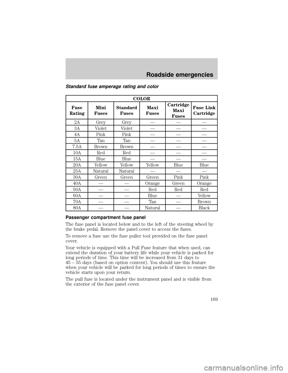
Standard fuse amperage rating and color
COLOR
Fuse
RatingMini
FusesStandard
FusesMaxi
FusesCartridge
Maxi
FusesFuse Link
Cartridge
2A Grey Grey Ð Ð Ð
3A Violet Violet Ð Ð Ð
4A Pink Pink Ð Ð Ð
5A Tan Tan Ð Ð Ð
7.5A Brown Brown Ð Ð Ð
10A Red Red Ð Ð Ð
15A Blue Blue Ð Ð Ð
20A Yellow Yellow Yellow Blue Blue
25A Natural Natural Ð Ð Ð
30A Green Green Green Pink Pink
40A Ð Ð Orange Green Orange
50A Ð Ð Red Red Red
60A Ð Ð Blue Ð Yellow
70A Ð Ð Tan Ð Brown
80A Ð Ð Natural Ð Black
Passenger compartment fuse panel
The fuse panel is located below and to the left of the steering wheel by
the brake pedal. Remove the panel cover to access the fuses.
To remove a fuse use the fuse puller tool provided on the fuse panel
cover.
Your vehicle is equipped with a Pull Fuse feature that when used, can
extend the duration of your battery life while your vehicle is parked for
long periods of time. This time will be increased from 31 days to
45 ± 55 days (based on option content). You should use this feature
when your vehicle will be parked for long periods of times to ensure the
vehicle starts upon your return.
The pull fuse is located under the instrument panel and is visible from
the exterior of the fuse panel cover.
Roadside emergencies
169