1999 FORD WINDSTAR fuel pump
[x] Cancel search: fuel pumpPage 23 of 248
![FORD WINDSTAR 1999 2.G Owners Manual 9. Slowly drive the vehicle in a
circle (less than 5 km/h [3 mph])
until the CIRCLE SLOWLY TO
CALIBRATE indicator changes to
CALIBRATION COMPLETED. This
will take up to three circles to complete calib FORD WINDSTAR 1999 2.G Owners Manual 9. Slowly drive the vehicle in a
circle (less than 5 km/h [3 mph])
until the CIRCLE SLOWLY TO
CALIBRATE indicator changes to
CALIBRATION COMPLETED. This
will take up to three circles to complete calib](/manual-img/11/5415/w960_5415-22.png)
9. Slowly drive the vehicle in a
circle (less than 5 km/h [3 mph])
until the CIRCLE SLOWLY TO
CALIBRATE indicator changes to
CALIBRATION COMPLETED. This
will take up to three circles to complete calibration.
10. The compass is now calibrated.
FUEL ECON AVG
Select this function from the INFO
menu to display your average fuel
economy in liters/100 km or
miles/gallon.
If you calculate your average fuel
economy by dividing liters of fuel used by 100 kilometers traveled (miles
traveled by gallons used), your figure may be different than displayed for
the following reasons:
²your vehicle was not perfectly level during fill-up
²differences in the automatic shut-off points on the fuel pumps at
service stations
²variations in top-off procedure from one fill-up to another
²rounding of the displayed values to the nearest 0.1 liter (gallon)
1. Drive the vehicle at least 8 km (5 miles) with the speed control
system engaged to display a stabilized average.
2. Record the highway fuel economy for future reference.
It is important to press the RESET control after setting the speed
control to get accurate highway fuel economy readings.
DIST TO EMPTY (DTE)
Selecting this function from the
INFO menu will give you an
estimate of how far you can drive
with the fuel remaining in your tank
under normal driving conditions.
Remember to turn the ignition OFF when refueling your vehicle.
Otherwise, the display will not show the addition of fuel for a few
kilometers (miles).
Instrumentation
23
Page 167 of 248

HAZARD FLASHER
Use only in an emergency to warn traffic of vehicle breakdown,
approaching danger, etc. The hazard flashers can be operated when the
ignition is off.
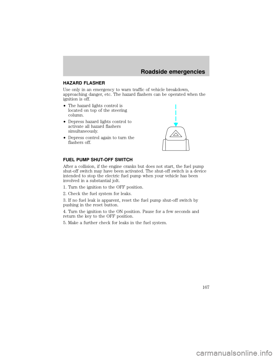
²The hazard lights control is
located on top of the steering
column.
²Depress hazard lights control to
activate all hazard flashers
simultaneously.
²Depress control again to turn the
flashers off.
FUEL PUMP SHUT-OFF SWITCH
After a collision, if the engine cranks but does not start, the fuel pump
shut-off switch may have been activated. The shut-off switch is a device
intended to stop the electric fuel pump when your vehicle has been
involved in a substantial jolt.
1. Turn the ignition to the OFF position.
2. Check the fuel system for leaks.
3. If no fuel leak is apparent, reset the fuel pump shut-off switch by
pushing in the reset button.
4. Turn the ignition to the ON position. Pause for a few seconds and
return the key to the OFF position.
5. Make a further check for leaks in the fuel system.
Roadside emergencies
167
Page 168 of 248

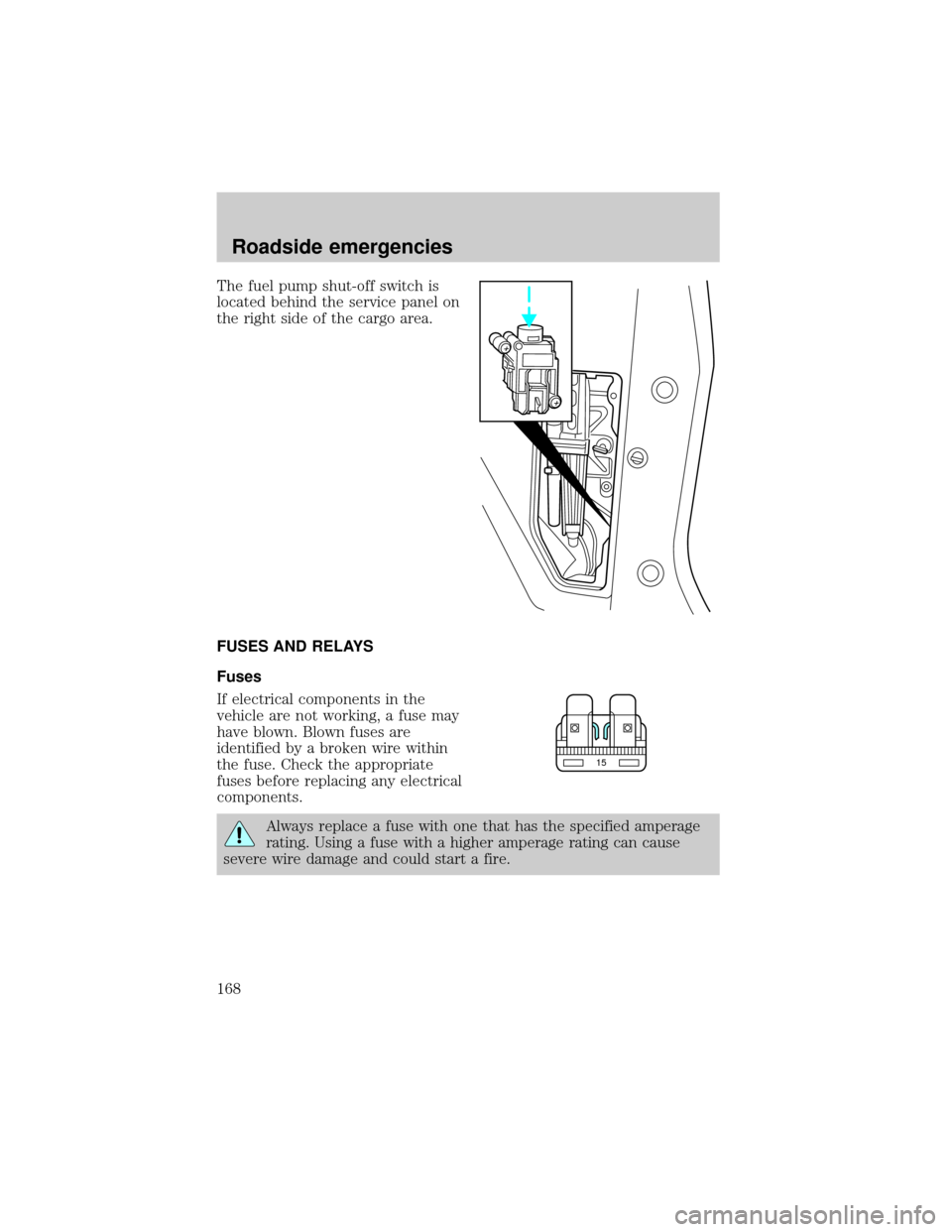
The fuel pump shut-off switch is
located behind the service panel on
the right side of the cargo area.
FUSES AND RELAYS
Fuses
If electrical components in the
vehicle are not working, a fuse may
have blown. Blown fuses are
identified by a broken wire within
the fuse. Check the appropriate
fuses before replacing any electrical
components.
Always replace a fuse with one that has the specified amperage
rating. Using a fuse with a higher amperage rating can cause
severe wire damage and could start a fire.
15
Roadside emergencies
168
Page 174 of 248

The high-current fuses are coded as follows:
Fuse/Relay
LocationFuse Amp
RatingDescription
1 30A* Powertrain Control Module Relay
2 10A* Powertrain Control Module, Front Electronic
Module
3 10A* A/C Compressor Clutch
4 25A* Horns, Horn Relay (coil)
5 15A* Fuel Pump Motor, Powertrain Control Module
6 30A* Front Wiper Motor, Front Wiper Relay, Front
Washer Pump, FEM
7 25A* Rear Wiper Motor, Rear Washer Pump, Rear
Wiper Relay (coil)
8 Ð Not Used
9 Ð Not Used
10 Ð Not Used
11 Ð Not Used
12 Ð Not Used
13 Ð Not Used
14 Ð Not Used
15 15A* Right Headlamp (Low and High Beam)
16 15A* Left Headlamp (Low and High Beam)
17 Ð Not Used
18 Ð Not Used
19 15A* AX4S Transaxle, Vapor Management Valve,
A/C Clutch Relay Coil, EGR Control Solenoid,
Engine Fuel Control HO2S #11 Sensor,
Engine Fuel Control HO2S #21 Sensor,
Catalyst Monitor HO2S #12 Sensor, Catalyst
Monitor HO2S #22 Sensor, Canister Vent
Solenoid
Roadside emergencies
174
Page 175 of 248

Fuse/Relay
LocationFuse Amp
RatingDescription
20 15A* Ignition Coil, Intake Air Control Valve, Fuel
Injectors #1, #2, #3, #4, #5, #6, Mass Air Flow
Sensor, Fuel Pump Relay Coil, Intake
Manifold Runner Control, HI-Speed Cooling
Fan Relay Coil, LO-Speed Cooling Fan Relay
Coil, Powertrain Control Module
21 10A* Front Electronic Module
(LH Door Lock Motor)
22 15A* Right Front Park Lamp, Right Front Turn
Lamp, Right Front Cornering Lamp
23 15A* Left Front Park Lamp, Left Front Turn Lamp,
Left Front Cornering Lamp
24 Ð Not Used
101 40A** ABS Module
102 40A** ABS Module
103 40A** SSP4 Relay, SSP4 Relay (coil)
104 40A** LH Power Seat Motors, LH Power Lumbar
Motor
105 30A** Starter Motor Solenoid, Ignition Switch
106 30A** Delayed Accessory Relay, Delayed Accessory
Relay (coil), Front Electronic Module, RHF
Window Motor
107 50A** RH/LH Engine Cooling Fan Motors, Cooling
Fan Dropping Resistor
108 40A** SSP2 Relay, SSP2 Relay (coil)
109 40A** SSP1 Relay, SSP1 Relay (coil)
110 50A** RH Power Sliding Door Module
111 Ð Not Used
112 30A** Electric Brake Controller
113 30A** Front Electronic Module (LH Window Motor)
114 40A** SSP3 Relay, SSP3 Relay (coil)
115 50A** Fuse Junction Box Bus #2
Roadside emergencies
175
Page 176 of 248

Fuse/Relay
LocationFuse Amp
RatingDescription
116 30A** Heated Backlight Relay
117 40A** Auxiliary Blower Relay (coil), Auxiliary
Blower Motor
118 50A** LH Power Sliding Door Module
119 30A** Fuse Junction Box Bus #1
120 40A** Front Blower Relay (coil), Front Blower
Motor
121 20A** Ignition Switch, Rear Defrost Relay (coil)
122 40A** RH Power Seat Motors, RH Power Lumbar
Motor
201 Ð Not Used
202 Ð Front Wiper ON/OFF Relay
203 Ð Rear Wiper Relay
204 Ð A/C Clutch Relay
205 Ð Horn Relay
206 Ð Not Used
207 Ð Fuel Pump Relay
208 Ð Not Used
209 Ð Front Wiper Hi/Low Relay
301 Ð SSP2 Relay
302 Ð Start Interrupt Relay
303 Ð SSP1 Relay
304 Ð Powertrain Control Module Relay
401 Ð Not Used
501 Ð Powertrain Control Module Diode
502 Ð A/C Clutch Diode
503 Ð Not Used
* Mini Fuses ** Maxi Fuses
Roadside emergencies
176
Page 218 of 248

Running out of fuel
Avoid running out fuel because this situation may have an adverse affect
on powertrain components.
If you have run out of fuel:
²You may need to crank the engine several times before the system
starts to pump fuel from the tank to the engine.
²Your ªCheck Engineº light may come on. For more information on the
ªCheck Engineº light, refer to theInstrumentationchapter.
Fuel Filter
Your vehicle is equipped with a fuel filter that is mounted on the
underbody.
For fuel filter replacement, see your dealer or a qualified service
technician. Refer to the Scheduled Maintenance Guide for the
appropriate intervals for changing the fuel filter.
If you replace the fuel filter, replace it with an authorized
Motorcraft part. The customer warranty may be void for any
damage to the fuel system if an authorized Motorcraft fuel filter
is not used.
ESSENTIALS OF GOOD FUEL ECONOMY
Measuring techniques
Your best source of information about actual fuel economy is you, the
driver. You must gather information as accurately and consistently as
possible. Fuel expense, frequency of fillups or fuel gauge readings are
NOT accurate as a measure of fuel economy. We do not recommend taking
fuel economy measurements during the first 1 600 km (1 000 miles) of
driving (engine break-in period). You will get a more accurate
measurement after 3 000 km±5 000 km (2 000 miles±3 000 miles).
The advertised fuel capacity of the fuel tank on your vehicle is equal to
the rated refill capacity of the fuel tank as listed in the Refill Capacities
chart in this ªOwner Guide.º The advertised capacity is the amount of
the Indicated Capacity and the Empty Reserve combined. Indicated
Capacity is the difference in the amount of fuel in a full tank and a tank
when the fuel gauge indicates empty. Empty Reserve is the small amount
of usable fuel remaining in the fuel tank after the fuel gauge indicates
empty.
Maintenance and care
218
Page 219 of 248

The amount of Empty Reserve varies and should not be relied
upon to increase driving range. When refueling your vehicle after
the fuel gauge indicates empty, you might not be able to refuel
the full amount of the advertised capacity of the fuel tank due to
the empty reserve still present in the tank.
Filling the tank
For consistent results:
²Use the same filling rate setting (low Ð medium Ð high) each time
the tank is filled.
²Allow three automatic click-offs when filling.
²Always use the recommended octane rating of a known quality
gasoline, preferably a national brand.
²Use the same side of the same pump and have the vehicle facing the
same direction each time you fill up.
²Have the vehicle loading and distribution the same every time.
Your results will be most accurate if your filling method is consistent.
Calculating fuel economy
1. Fill the fuel tank completely and record the initial odometer reading.
2. Each time you fill the tank, record the amount of fuel added (in liters
or gallons).
3. After at least three to five tank fill-ups, fill the fuel tank and record
the current kilometer (mileage) reading.
4. Follow one of the simple calculations in order to determine fuel
economy:
Multiply liters used by 100, then divide by total kilometers
traveled.
Divide total miles traveled by total gallons used.
Keep a record for at least one month and record the type of driving (city
or highway). This will provide an accurate estimate of the vehicle's fuel
economy. Additionally, keeping records during summer and winter will
show how temperature impacts fuel economy. In general, lower
temperatures give lower fuel economy.
Maintenance and care
219