Page 148 of 232

If you are driving more than 24 km (15 miles) at temperatures above
freezing, angle the plow blade either full left or full right to provide
maximum airflow to the radiator.
If you are driving less than 24 km (15 miles) at speeds up to 64 km/h
(40 mph) in cold weather, you will not need to worry about blade
position to provide maximum airflow.
Transmission operation while plowing
²Shift transfer case to 4L (4WD Low) when plowing in small areas at
speeds below 8 km/h (5 mph).
²Shift transfer case to 4H (4WD High) when plowing larger areas or
light snow at higher speeds. Do not exceed 24 km/h (15 mph).
²Do not shift the transmission from a forward gear to R (Reverse) until
the engine is at idle and the wheels are stopped.
²If the vehicle is stuck, shift the transmission in a steady motion
between forward and reverse gears. Do not rock the vehicle for more
than a few minutes. The transmission and tires may be damaged or
the engine can overheat.
Do not spin the wheels at over 35 mph (55 km/h). The tires may
fail and injure a passenger or bystander.
Driving
148
Page 149 of 232

HAZARD FLASHER
Use only in an emergency to warn traffic of vehicle breakdown,
approaching danger, etc. The hazard flashers can be operated when the
ignition is off.
²The hazard lights control is
located on top of the steering
column.
²Depress hazard lights control to
activate all hazard flashers
simultaneously.
²Depress control again to turn the
flashers off.
FUEL PUMP SHUT-OFF SWITCH
After a collision, if the engine cranks but does not start, the fuel pump
shut-off switch may have been activated. The ªFuel Resetº indicator light
will illuminate in the instrument cluster. The shut-off switch is a device
intended to stop the electric fuel pump when your vehicle has been
involved in a substantial jolt.
1. Turn the ignition to the OFF position.
2. Check the fuel system for leaks.
3. If no fuel leak is apparent, reset the fuel pump shut-off switch by
pushing in the reset button.
4. Turn the ignition to the ON position. Pause for a few seconds and
return the key to the OFF position.
5. Make a further check for leaks in the fuel system.
Roadside emergencies
149
Page 152 of 232
The fuses are coded as follows.
Fuse/Relay
LocationFuse Amp
RatingDescription
1 15A Audio
2 5A Powertrain Control Module (PCM), Cluster
3 20A Cigar Lighter, OBD-II Scan Tool Connector
4 15A Autolamp Module, Remote Entry Module,
Mirrors
5 15A AC Clutch Relay, Speed Control Module,
Reverse Lamp, Climate Mode Switch,
Daytime Running Lamp Relay
6 5A Cluster, Brake Shift Interlock Solenoid,
Rear Air Suspension Module, GEM Module
7 Ð Not Used
8 5A Radio, Remote Entry Module, GEM Module
9 Ð Not Used
FUSE1 12 22
21323
617 27
718 28
819 29
930
20
31 21 11 10
RELAY
5 RELAY
4 RELAY
3 RELAY
2 RELAY
1
31424
41525
51626
Roadside emergencies
152
Page 158 of 232

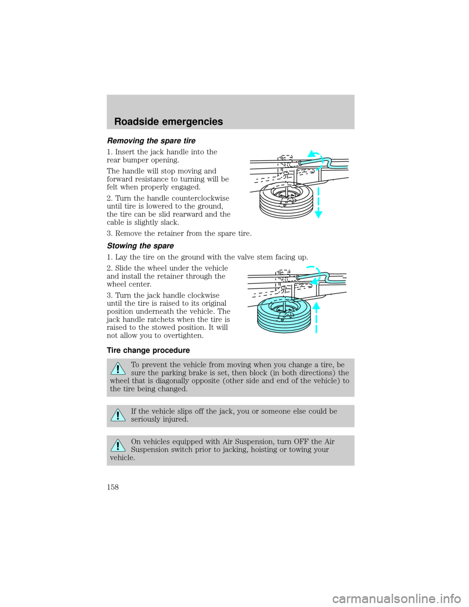
Removing the spare tire
1. Insert the jack handle into the
rear bumper opening.
The handle will stop moving and
forward resistance to turning will be
felt when properly engaged.
2. Turn the handle counterclockwise
until tire is lowered to the ground,
the tire can be slid rearward and the
cable is slightly slack.
3. Remove the retainer from the spare tire.
Stowing the spare
1. Lay the tire on the ground with the valve stem facing up.
2. Slide the wheel under the vehicle
and install the retainer through the
wheel center.
3. Turn the jack handle clockwise
until the tire is raised to its original
position underneath the vehicle. The
jack handle ratchets when the tire is
raised to the stowed position. It will
not allow you to overtighten.
Tire change procedure
To prevent the vehicle from moving when you change a tire, be
sure the parking brake is set, then block (in both directions) the
wheel that is diagonally opposite (other side and end of the vehicle) to
the tire being changed.
If the vehicle slips off the jack, you or someone else could be
seriously injured.
On vehicles equipped with Air Suspension, turn OFF the Air
Suspension switch prior to jacking, hoisting or towing your
vehicle.
Roadside emergencies
158
Page 163 of 232
5. Turn the heater fan on in both vehicles to protect any electrical
surges. Turn all other accessories off.
Connecting the jumper cables
1. Connect the positive (+) booster cable to the positive (+) terminal of
the discharged battery.
Note:In the illustrations,lightning boltsare used to designate the
assisting (boosting) battery.
2. Connect the other end of the positive (+) cable to the positive (+)
terminal of the assisting battery.
+–+–
+–+–
Roadside emergencies
163
Page 168 of 232

SERVICE RECOMMENDATIONS
To help you service your vehicle:
²We highlight do-it-yourself items in the engine compartment for easy
location.
²We provide a Scheduled Maintenance Guide which makes tracking
routine service easy.
If your vehicle requires professional service, your dealership can provide
necessary parts and service. Check your ªWarranty Guideº to find out
which parts and services are covered.
Use only recommended fuels, lubricants, fluids and service parts
conforming to specifications. Motorcraft parts are designed and built to
provide the best performance in your vehicle.
PRECAUTIONS WHEN SERVICING YOUR VEHICLE
Be especially careful when inspecting or servicing your vehicle.
²Do not work on a hot engine.
²When the engine is running, keep loose clothing, jewelry or long hair
away from moving parts.
²Do not work on a vehicle with the engine running in an enclosed
space, unless you are sure you have enough ventilation.
²Keep all lit cigarettes, open flames and other lit material away from
the battery and all fuel related parts.
If you disconnect the battery, the engine must ªrelearnº its idle
conditions before your vehicle will drive properly, as explained in the
Batterysection in this chapter.
Working with the engine off
²Automatic transmission:
1. Set the parking brake and ensure the gearshift is securely latched in P
(Park).
2. Turn off the engine and remove the key.
3. Block the wheels to prevent the vehicle from moving unexpectedly.
²Manual transmission:
1. Set the parking brake.
2. Depress the clutch and place the gearshift in 1 (First).
Maintenance and care
168
Page 176 of 232
1. Clean the reservoir cap before
removal to prevent dirt and water
from entering the reservoir.
2. Remove cap and rubber
diaphragm from reservoir.
3. Add fluid until the level reaches
the step in the reservoir.
4. Reinstall rubber diaphragm and
cap onto reservoir.
WINDSHIELD WASHER FLUID
Checking and adding washer fluid
Check the washer fluid whenever
you stop for fuel. The reservoir is
highlighted with a
symbol.
If the level is low, add enough fluid
to fill the reservoir. In very cold
weather, do not fill the reservoir all
the way.
Do not put engine coolant in the container for the windshield
washer fluid.
Maintenance and care
176
Page 179 of 232

Not all coolant recycling processes produce coolant which meets Ford
specification ESE-M97B44±A, and use of such coolant may harm engine
and cooling system components.
Always dispose of used automotive fluids in a responsible manner.
Follow your community's regulations and standards for recycling and
disposing of automotive fluids.
Coolant refill capacity
To find out how much fluid your vehicle's cooling system can hold, refer
toRefill capacitiesin theCapacities and specificationschapter.
Have your dealer check the engine cooling system for leaks if you have
to add more than 1.0 liter (1.0 quart) of engine coolant per month.
Severe winter climate
If you drive in extremely cold climates (less than ±36ÉC [±34ÉF]), it may
be necessary to increase the coolant concentration above 50%. Refer to
the chart on the coolant container to ensure the coolant concentration in
your vehicle is such that the coolant will not freeze at the temperature
level in which you drive during winter months. Never increase the engine
coolant concentration above 60%. Leave a 50/50 mixture of engine
coolant and water in your vehicle year-round in non-extreme climates.
What you should know about fail-safe cooling (if equipped)
If the engine coolant supply is depleted, this feature allows the vehicle to
be driven temporarily before incremental component damage is incurred.
The ªfail-safeº distance depends on ambient temperatures, vehicle load
and terrain.
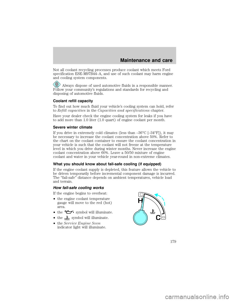
How fail-safe cooling works
If the engine begins to overheat:
²the engine coolant temperature
gauge will move to the red (hot)
area.
²the
symbol will illuminate.
²the
symbol will illuminate.
²theService Engine Soon
indicator light will illuminate.C
H
Maintenance and care
179