1999 DODGE RAM fuel
[x] Cancel search: fuelPage 614 of 1691

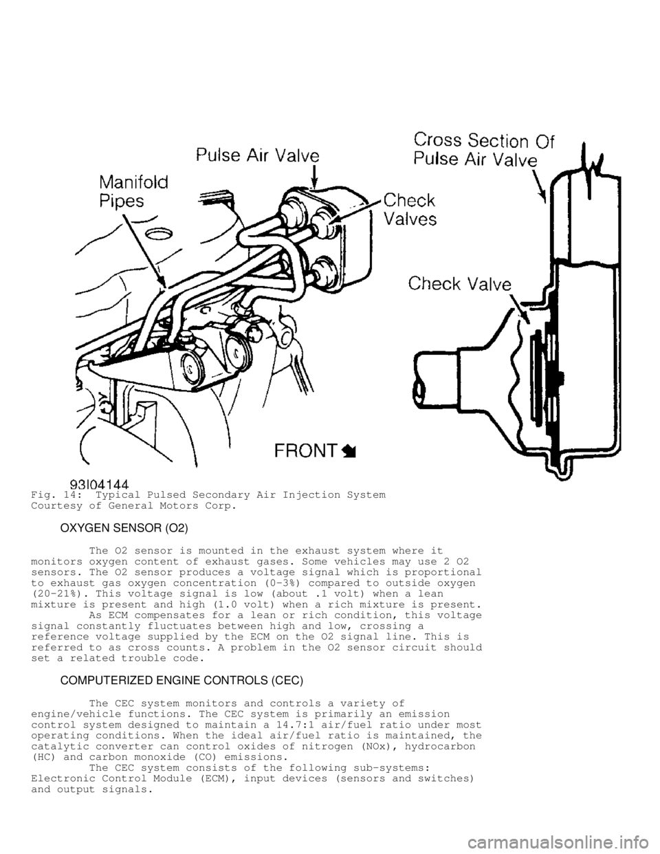
Fig. 14: Typical Pulsed Secondary Air Injection System
Courtesy of General Motors Corp.
OXYGEN SENSOR (O2)
The O2 sensor is mounted in the exhaust system where it
monitors oxygen content of exhaust gases. Some vehicles may use 2 O2
sensors. The O2 sensor produces a voltage signal which is proportional
to exhaust gas oxygen concentration (0-3%) compared to outside oxygen
(20-21%). This voltage signal is low (about .1 volt) when a lean
mixture is present and high (1.0 volt) when a rich mixture is present.\
As ECM compensates for a lean or rich condition, this voltage
signal constantly fluctuates between high and low, crossing a
reference voltage supplied by the ECM on the O2 signal line. This is
referred to as cross counts. A problem in the O2 sensor circuit should
set a related trouble code.
COMPUTERIZED ENGINE CONTROLS (CEC)
The CEC system monitors and controls a variety of
engine/vehicle functions. The CEC system is primarily an emission
control system designed to maintain a 14.7:1 air/fuel ratio under most
operating conditions. When the ideal air/fuel ratio is maintained, the
catalytic converter can control oxides of nitrogen (NOx), hydrocarbon
(HC) and carbon monoxide (CO) emissions.
The CEC system consists of the following sub-systems:
Electronic Control Module (ECM), input devices (sensors and switches)\
and output signals.
Page 615 of 1691

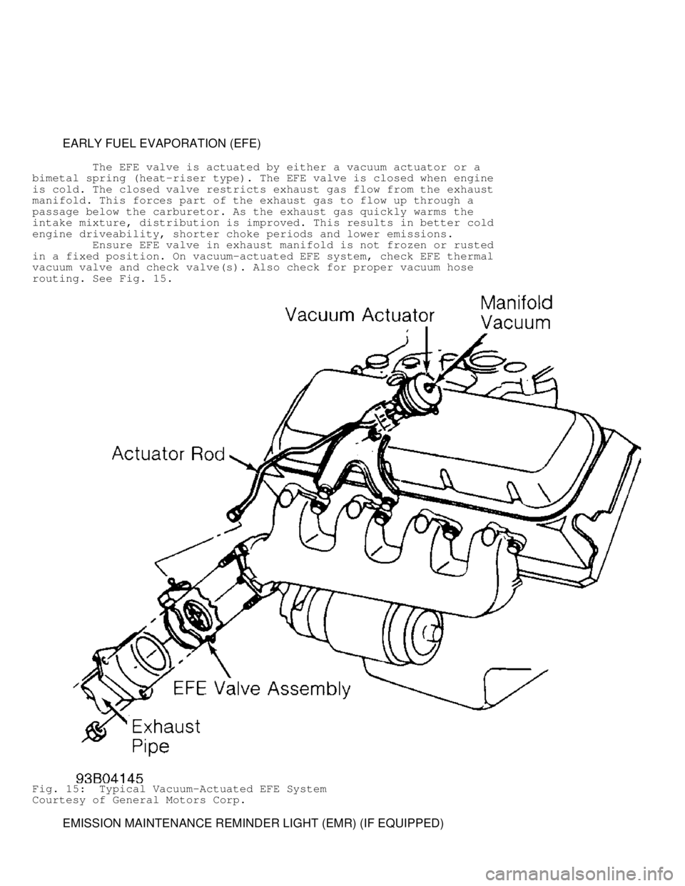
EARLY FUEL EVAPORATION (EFE)
The EFE valve is actuated by either a vacuum actuator or a
bimetal spring (heat-riser type). The EFE valve is closed when engine
is cold. The closed valve restricts exhaust gas flow from the exhaust
manifold. This forces part of the exhaust gas to flow up through a
passage below the carburetor. As the exhaust gas quickly warms the
intake mixture, distribution is improved. This results in better cold
engine driveability, shorter choke periods and lower emissions.
Ensure EFE valve in exhaust manifold is not frozen or rusted
in a fixed position. On vacuum-actuated EFE system, check EFE thermal
vacuum valve and check valve(s). Also check for proper vacuum hose
routing. See Fig. 15.
Fig. 15: Typical Vacuum-Actuated EFE System
Courtesy of General Motors Corp.
EMISSION MAINTENANCE REMINDER LIGHT (EMR) (IF EQUIPPED)
Page 630 of 1691

TROUBLE SHOOTING
NOTE: To trouble shoot mechanical engine components, see
appropriate table in TROUBLE SHOOTING article in GENERAL
INFORMATION.
REMOVAL & INSTALLATION
CAUTION: When battery is disconnected, vehicle computer and memory
systems may lose memory data. Driveability problems may exist
until computer systems have completed a relearn cycle. See
COMPUTER RELEARN PROCEDURES article in GENERAL INFORMATION
before disconnecting battery.
NOTE: For installation reference, label all electrical connectors,
vacuum hoses and fuel lines before removal. Also place mating
marks on engine hood and other major assemblies before
removal.
FUEL PRESSURE RELEASE
CAUTION: Fuel system is under pressure. Pressure must be released
before servicing fuel system components.
Gasoline
1) Disconnect negative battery cable. Loosen fuel tank cap to
release tank pressure. Press on filler tube flap to relieve any
additional tank pressure.
NOTE: Fuel filler tube has spring-loaded flap located below fuel
fill cap to serve as secondary seal if fuel fill cap is not
tightened. It is part of EVAP monitor system when vehicle is
equipped with leak detection pump (LDP). Vehicle may be
equipped with flap installed into fuel filler tube even if
vehicle is NOT equipped with LDP and EVAP monitor system.
2) Remove fuel pump relay from Power Distribution Center
(PDC). For location of relay, refer to label on underside of PDC
cover. Start and run engine until it stalls. Attempt restarting engine
until it will no longer run.
3) Unplug connector from an injector. Attach one end of a
jumper wire (18 gauge or smaller) with alligator clips to either
injector terminal. Connect other end of jumper wire to positive side
of battery. Connect one end of a second jumper wire to remaining
injector terminal.
WARNING: Powering an injector for more than a few seconds will
permanently damage injector.
4) Touch other end of second jumper wire to negative terminal
of battery for no more than a few seconds. Place a rag below fuel
line. Disconnect quick-connect fitting at fuel rail. See FUEL LINE
DISCONNECT FITTINGS. Return fuel pump relay to PDC.
Compressed Natural Gas Fuel Tube Purging (5.2L)
1) Close control valve (clockwise) on all fuel cylinders.
Open manual shutoff valve (open when handle is parallel to fuel
tubes).
2) Start and operate engine until it runs out of fuel.
Attempt 3 more engine starts. If check valve or fuel fill receptacle
Page 631 of 1691

is to be serviced, slowly loosen inlet side of fuel fill tube fitting
at check valve. It is normal for approximately 25 psi of residual
natural gas pressure to flow from loosened fitting. At this point, all
fuel tubes are purged of natural gas between fuel cylinders and
engine. It is now okay to open fuel system.
WARNING: Fuel cylinders still contain high-pressure fuel.
Compressed Natural Gas Fuel Cylinder Purging (5.2L)
1) Open manual shutoff valve. Open only fuel control valve(s)\
(counterclockwise) on fuel cylinder(s) to be serviced. Close all oth\
er
control valve(s) (clockwise) on fuel cylinder(s) not being service\
d.
2) Start and operate engine until it runs out of fuel.
Attempt 3 more engine starts. At this point, all fuel tubes and opened
cylinders are purged of natural gas between fuel cylinders and engine.
It is now okay to open fuel system.
WARNING: Fuel cylinders not being serviced still contain high-pressure
fuel.
FUEL LINE DISCONNECT FITTINGS
Removal & Installation (Tab Type Fitting)
1) Release fuel pressure. See FUEL PRESSURE RELEASE.
Disconnect negative battery cable. Ensure area around fuel line and
disconnect fitting is clean. Place shop towel around fuel line.
2) On 2-tab connectors, squeeze retainer tabs together and
pull fuel tube/quick-connect fitting assembly off of fuel tube nipple.
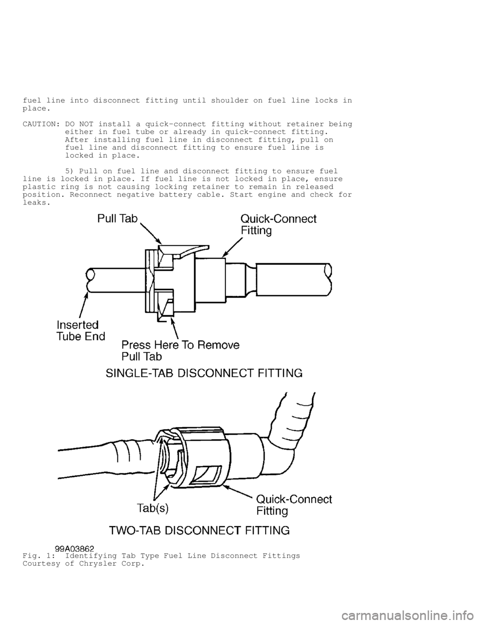
On single-tab connectors, use screwdriver to pry up pull tab. See
Fig. 1 . Raise pull tab until it separates from quick-connect fitting.
Discard old pull tab. Disconnect quick-connect fitting from fuel line.
CAUTION: DO NOT install a quick-connect fitting without retainer being
either in fuel tube or already in quick-connect fitting.
After installing fuel line in disconnect fitting, pull on
fuel line and disconnect fitting to ensure fuel line is
locked in place.
3) To install, coat fuel tube nipple with clean 30W engine
oil. Insert quick-connect fitting into fuel tube until stop on fuel
tube rests against back of quick-connect fitting.
4) On single-tab connectors, obtain NEW pull tab. Push tab
down until it locks into quick-connect fitting. On 2-tab connectors,
firmly pull on fuel tube and fitting to ensure retainer and quick-
connect fitting are locked.
Removal & Installation (Retainer Type Fitting)
1) Release fuel pressure. See FUEL PRESSURE RELEASE.
Disconnect negative battery cable. Ensure area around fuel line and
disconnect fitting is clean. Place shop towel around fuel line.
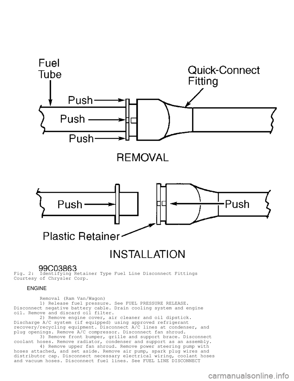
2) Pull backward on disconnect fitting while depressing
plastic ring into disconnect fitting. See Fig. 2. Separate fuel line
from disconnect fitting.
NOTE: Plastic retainer ring must be pressed squarely into fitting
body. If retainer is cocked during removal, it may be
difficult to disconnect fitting. Use open-end wrench on
shoulder of plastic retainer to ease disconnection.
3) To install, ensure plastic ring is in outward position
(away from disconnect fitting). If plastic ring is in inward position
(toward disconnect fitting), disconnect fitting must be replaced.
4) Lubricate end of fuel line with 30W engine oil. Insert
Page 632 of 1691

fuel line into disconnect fitting until shoulder on fuel line locks in
place.
CAUTION: DO NOT install a quick-connect fitting without retainer being
either in fuel tube or already in quick-connect fitting.
After installing fuel line in disconnect fitting, pull on
fuel line and disconnect fitting to ensure fuel line is
locked in place.
5) Pull on fuel line and disconnect fitting to ensure fuel
line is locked in place. If fuel line is not locked in place, ensure
plastic ring is not causing locking retainer to remain in released
position. Reconnect negative battery cable. Start engine and check for
leaks.
Fig. 1: Identifying Tab Type Fuel Line Disconnect Fittings
Courtesy of Chrysler Corp.
Page 633 of 1691

Fig. 2: Identifying Retainer Type Fuel Line Disconnect Fittings
Courtesy of Chrysler Corp.
ENGINE
Removal (Ram Van/Wagon)
1) Release fuel pressure. See FUEL PRESSURE RELEASE.
Disconnect negative battery cable. Drain cooling system and engine
oil. Remove and discard oil filter.
2) Remove engine cover, air cleaner and oil dipstick.
Discharge A/C system (if equipped) using approved refrigerant
recovery/recycling equipment. Disconnect A/C lines at condenser, and
plug openings. Remove A/C compressor. Disconnect fan shroud.
3) Remove front bumper, grille and support brace. Disconnect
coolant hoses. Remove radiator, condenser and support as an assembly.
4) Remove upper fan shroud. Remove power steering pump with
hoses attached, and set aside. Remove air pump, spark plug wires and
distributor cap. Disconnect necessary electrical wiring, coolant hoses
and vacuum hoses. Disconnect fuel lines. See FUEL LINE DISCONNECT
Page 634 of 1691

FITTINGS. Remove air cleaner, throttle body, drive belts, generator,
fan and fan pulley. Remove lower fan shroud.
CAUTION: When removing engine, DO NOT lift engine by intake manifold.
5) Remove intake manifold. See INTAKE MANIFOLD. Raise and
support vehicle. Remove starter. Remove exhaust pipe and heat shields.
Disconnect transmission shift linkage. Remove crank sensor.
6) On A/T models, remove transmission inspection cover. Mark
torque converter-to-flexplate position for installation reference.
Remove torque converter-to-flexplate bolts. On M/T models, disconnect
clutch release mechanism at clutch housing.
7) Attach engine hoist to cylinder heads (at intake manifold
flanges). On all models, support transmission using a floor jack.
Remove transmission or clutch housing-to-cylinder block bolts. Remove
engine mount bolts. Remove engine out front of vehicle.
Installation
To install, reverse removal procedure. Tighten bolts/nuts to
specification. See TORQUE SPECIFICATIONS table. On A/T models, ensure
reference marks on torque converter and flexplate are aligned.
Evacuate and charge A/C system.
Removal ( Dakota 2WD, Durango 2WD, Grand Cherokee & Ram
Pickup)
1) Release fuel pressure. See FUEL PRESSURE RELEASE.
Disconnect and remove battery. On all except Pickup, scribe hood
hinges for installation reference and remove hood.
2) On all models, drain cooling system. Disconnect coolant
hoses. Remove radiator, fan and shroud. Discharge A/C system (if
equipped) using approved refrigerant recovery/recycling equipment.
Disconnect A/C lines, and plug openings. On Pickup, remove upper core
support, transmission cooler and A/C condenser. On all models, remove
belt, air cleaner, vacuum lines, distributor cap and wiring.
3) Disconnect necessary electrical wiring. Disconnect fuel
lines. See FUEL LINE DISCONNECT FITTINGS. Remove throttle body and
linkage. Remove intake manifold. Remove starter, generator, charcoal
canister and horns. Disconnect power steering hoses (if equipped).
Raise and support vehicle. Drain oil. Disconnect exhaust pipe at
exhaust manifold.
4) On A/T models, remove transmission housing inspection
plate. Mark torque converter-to-flexplate position for installation
reference. Remove torque converter-to-flexplate bolts. Remove bracket
for transmission cooler lines.
NOTE: It may be necessary to remove manual transmission if
transmission cannot be supported using floor jack.
5) On M/T models, disconnect clutch release mechanism at
clutch housing. On all models, support transmission using a floor
jack. Remove transmission or clutch housing-to-cylinder block bolts.
Install engine lifting fixture, and attach chain.
CAUTION: When removing engine, DO NOT lift engine by intake manifold.
6) On Ram Pickup and Grand Cherokee, remove front engine
mount bolts. Remove engine from vehicle. On Dakota 2WD and Durango 2WD
models, remove front engine mount through-bolts. See Fig. 3. Remove
engine from vehicle.
Installation
To install, reverse removal procedure. Tighten bolts/nuts to
specification. See TORQUE SPECIFICATIONS table. On A/T models, ensure
Page 635 of 1691

reference marks on torque converter and flexplate are aligned.
Evacuate and charge A/C system.
Removal (Durango 4WD & Dakota 4WD)
1) Release fuel pressure. See FUEL PRESSURE RELEASE.
Disconnect and remove battery. Scribe hood hinges for installation
reference and remove hood.
2) Drain cooling system. Disconnect coolant hoses. Remove
radiator, fan and shroud. Discharge A/C system (if equipped) using
approved refrigerant recovery/recycling equipment. Disconnect A/C
lines, and plug openings. Remove air cleaner, vacuum lines,
distributor cap and wiring.
3) Disconnect necessary electrical wiring. Disconnect fuel
lines. See FUEL LINE DISCONNECT FITTINGS. Disconnect accelerator
linkage. Remove throttle body. Remove starter and generator.
Disconnect power steering hoses. Raise and support vehicle. Drain oil.
Disconnect exhaust pipe at exhaust manifold.
NOTE: Engine, transmission and front axle are connected and
supported with insulators and brackets. See Fig. 3.
4) On left side, remove 2 bolts attaching differential pinion
nose bracket-to-bellhousing bolts. Remove pinion nose bracket-to-
adapter bolts (located on top of differential, near pinion). Separate
engine from engine mount by removing engine mount through-bolt and nut
located on top of engine mount.
5) On right side, remove 2 axle-to-bracket bolts and bracket-
to-bellhousing bolt. Separate engine from engine mount by removing
engine mount through-bolt and nut located on top of engine mount.
Remove engine from vehicle.