1999 DODGE RAM Wiring diagram
[x] Cancel search: Wiring diagramPage 264 of 1691

19) Turn ignition on. Using scan tool, read governor pressure
sensor voltage. If voltage is 4.65 volts or less, replace PCM. If
resistance is greater than 4.65 volts, go to next step.
20) Turn ignition off. Drain transmission fluid and remove
oil pan. Disconnect pressure/temperature sensor harness connector.
Inspect connector and terminals for damage. Repair as necessary. If
connector and terminals are okay, reconnect transmission solenoid
harness connector. Measure resistance of governor pressure sensor
signal circuit between White PCM harness connector C2 and governor
pressure sensor harness connector. If resistance is greater than 5
ohms, repair or replace transmission solenoid and harness assembly. If
resistance is 5 ohms or less, go to next step.
21) Measure resistance of governor pressure sensor ground
circuit between Black PCM harness connector C1 and governor pressure
sensor harness connector. If resistance is greater than 5 ohms, repair
or replace transmission solenoid and harness assembly. If resistance
is 5 ohms or less, go to next step.
22) Turn ignition on. Measure voltage between ground and
governor pressure signal circuit at governor pressure sensor harness
connector. If voltage is greater than one volt, repair or replace
transmission solenoid and harness assembly. If voltage is one volt or
less, replace pressure/temperature sensor.
23) Check and record freeze frame data to determine
conditions which set code. Conditions required to set DTC P1764 are
not present at this time. Using wiring diagram as a guide, inspect
wiring and connectors. Repair wiring harness as necessary. If wiring
and connectors are okay, go to next step.
24) Using scan tool, clear DTCs. While reading DTCs, wiggle
wiring harness between PCM and governor pressure sensor. If DTC P1764
resets while wiggling wiring harness, repair wiring harness as
necessary. If DTC P1764 does not reset, go next step.
25) DTC P1764 sets if governor pressure sensor input is less
than .1 volt for 8.36 seconds. Possible causes are: PCM internally
shorted or open, incorrectly wired, dirty or corroded connectors or
open or shorted wiring. See INACTIVE DTC CONDITION under SELF-
DIAGNOSTIC SYSTEM. Testing is complete.
DTC P1765: TRANS 12-VOLT SUPPLY RELAY CNTRL CIRCUIT
Circuit Description
Circuit is monitored continuously while key is on. Code sets
if voltage on transmission control relay circuit at PCM is different
than expected voltage for 3 seconds.
Possible Causes
* Generator source circuit open.
* Transmission relay control circuit open.
* Transmission relay control circuit short to ground.
* Transmission control relay wiring harness defective.
* PCM defective.
* Transmission control relay defective.
Diagnostic Procedures
1) Using scan tool, read DTCs. On AN and DN bodies, go to
next step. On all except AN and DN bodies, if DTC SPECIFIC GOOD TRIPS
counter is not displayed or displayed count is not "0", go to step 9).
If DTC SPECIFIC GOOD TRIPS counter is displayed and displayed count is
"0", go to next step.
2) Using scan tool, actuate transmission control relay. If
transmission control relay does not click, go to step 5). If
transmission control relay clicks, go to next step.
3) Wiggle wiring harness between transmission control relay
Page 265 of 1691

and PCM. Ensure scan tool is still actuating transmission control
relay. If transmission control relay stops clicking, repair wiring
harness as necessary. If transmission control relay continues
clicking, go to next step.
4) Using wiring diagram as a guide, inspect wiring and
connectors. Repair wiring harness as necessary. If wiring and
connectors are okay, see INACTIVE DTC CONDITION under SELF-DIAGNOSTIC
SYSTEM. Testing is complete.
5) Remove transmission control relay. Inspect connector and
terminals for damage. Repair as necessary. If connector and terminals
are okay, turn ignition on. Using scan tool, actuate generator field.
Measure voltage between ground and generator source circuit at
transmission control relay harness connector. If voltage is 10 volts
or less, repair open generator source circuit. If voltage is greater
than 10 volts, go to next step.
6) Turn ignition off. Measure resistance between transmission
control relay terminals No. 85 and 86. If resistance is 100 ohms or
greater, replace transmission control relay. If resistance is less
than 100 ohms, go to next step.
7) Disconnect White PCM harness connector C2. Inspect
connector and terminals for damage. Repair as necessary. If connector
and terminals are okay, measure resistance between ground and
transmission relay control circuit at White PCM harness connector C2.
If resistance is less than 5 ohms, repair short to ground in
transmission relay control circuit. If resistance is 5 ohms or
greater, go to next step.
8) Measure resistance of transmission relay control circuit
between transmission control relay connector and White PCM harness
connector C2. If resistance is 5 ohms or greater, repair open
transmission relay control circuit. If resistance is less than 5 ohms,
replace PCM.
9) Conditions required to set DTC P1765 are not present at
this time. DTC P1765 sets if transmission control relay is not in a
state requested by PCM for greater than 3 seconds. Possible causes
are: faulty relay, open or shorted control circuit, faulty PCM or
faulty connector terminals. Inspect all related wiring and connectors.
Repair as necessary. If wiring and connectors are okay, erase DTCs.
Using scan tool, read DTCs while wiggling wiring harness between
governor pressure sensor and PCM. If DTC P1765 resets, repair wiring
harness as necessary. If DTC P1765 does not reset, see INACTIVE DTC
CONDITION under SELF-DIAGNOSTIC SYSTEM. Testing is complete.
DTC P1899: P/N SWITCH STUCK IN PARK OR IN GEAR
Circuit Description
Circuit is monitored with transmission in "D", "N" or "P"
position. Code sets if PCM detects an incorrect park/neutral switch
state for any given mode of vehicle operation.
Possible Causes
* Park Neutral Position (PNP) switch wiring harness
defective.
* PNP switch sense circuit open.
* PNP switch defective.
* PNP switch sense circuit short to ground.
* PNP switch stuck.
Diagnostic Procedures (AN, DN & WJ Bodies)
1) Using scan tool, read DTCs. On AN and DN bodies, go to
next step. On WJ body, if DTC SPECIFIC GOOD TRIPS counter is not
displayed or displayed count is not "0", go to step 8). If DTC
SPECIFIC GOOD TRIPS counter is displayed and displayed count is "0",
Page 267 of 1691

6) Disconnect PNP switch harness connector. Measure
resistance of PNP switch sense circuit between Black PCM harness
connector C1 and PNP switch harness connector. If resistance is less
than 5 ohms, replace PNP switch. If resistance is not as specified,
repair open in PNP switch sense circuit.
7) Conditions required to set DTC P1899 are not present at
this time. Using scan tool, check and record FREEZE FRAME data. Ensure
"CAUSED BY DTC" "P" code matches code on DTC screen. Using wiring
diagram as a guide, inspect wiring and connectors. Repair wiring
harness as necessary. If wiring and connectors are okay, does not
reset, see INACTIVE DTC CONDITION under SELF-DIAGNOSTIC SYSTEM.
Testing is complete.
TEST VER-2A (EXCEPT DIESEL)
NOTE: If Powertrain Control Module (PCM) is replaced, correct
vehicle mileage and Vehicle Identification Number (VIN) must
be programmed into PCM to prevent Diagnostic Trouble Codes
(DTCs) from being set in Anti-Lock Brake System (ABS) modul\
e
and Supplemental Restraint System (SRS) module. To program
PCM and clear DTCs from ABS and SRS modules, proceed to
appropriate procedure listed below. On models equipped with a
Smart Key Immobilizer Module (SKIM), if replacing Powertrain
Control Module (PCM), secret key data must also be updated to\
enable engine starting. To update secret key data, proceed to
appropriate procedure listed below.
Procedure For Programming PCM & Clearing DTCs From ABS & SRS
Modules
Connect scan tool to Data Link Connector (DLC). Using scan
tool, enter correct VIN and mileage into PCM. Using scan tool
manufacturer's instructions, clear DTCs from ABS and SRS modules. Go
to step 1)).
Procedure For Updating Secret Key Data
Connect scan tool to Data Link Connector (DLC). Go to ENGINE
and then MISC menus on scan tool. Place SKIM in SECURED ACCESS MODE by
using appropriate Personal Identification Number (PIN) for this
vehicle. PIN may be obtained from owner, vehicle's invoice, or from
manufacturer. Select UPDATE THE SECRET KEY DATA. Data will be
transferred from Smart Key Immobilizer Module (SKIM) to PCM. Go to
step 1)).
1) Inspect vehicle to ensure all engine components are
connected. Reassemble and reconnect components as necessary. If test
is being performed after performing a NO TROUBLE CODE (NTC) test, go
to next step. If test is being performed after performing an OBD-II
TROUBLE CODE test, perform TEST VER-5A. If test is being performed
after any other TROUBLE CODE test, go to step 3).
2) Check if initial symptom still exists. If initial or
another symptom exists, repair is not complete. Check for Technical
Service Bulletins (TSBs) that apply to symptom and see appropriate
TEST NTC-1A: NO TROUBLE CODE TEST MENU in ENGINE PERFORMANCE, or
appropriate TROUBLE SHOOTING - NO CODES article in ENGINE PERFORMANCE
for diagnosis by symptom. If initial symptom no longer exists, test is
complete. Go to step 8).
3) If any DTCs have not been diagnosed, perform appropriate
test(s) see appropriate SELF-DIAGNOSTIC TESTS in ENGINE PERFORMANCE.
If all DTCs have been diagnosed and repaired, go to next step.
4) If Powertrain Control Module (PCM) has not been replaced,\
use scan tool to clear DTCs from PCM. Using scan tool, reset all
values in adaptive memory. To ensure no other DTCs remain, go to next
step.
Page 272 of 1691

OUTPUT SHAFT SPEED SENSOR
NOTE: Transmission output shaft speed sensor may also be referred
to as transmission shaft speed sensor or shaft speed sensor.
Removal & Installation
1) Disconnect electrical connector from output shaft speed
sensor, located on case of overdrive unit. Remove output shaft speed
sensor with "O" ring.
2) To install, reverse removal procedure using NEW "O" ring.
Tighten output shaft speed sensor to specification.
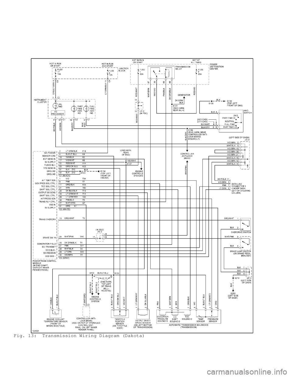
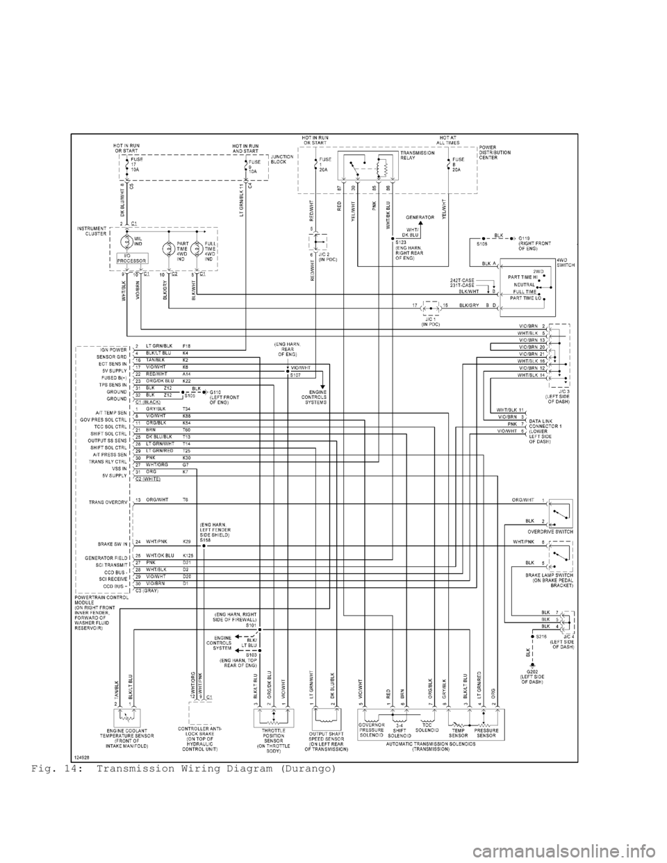
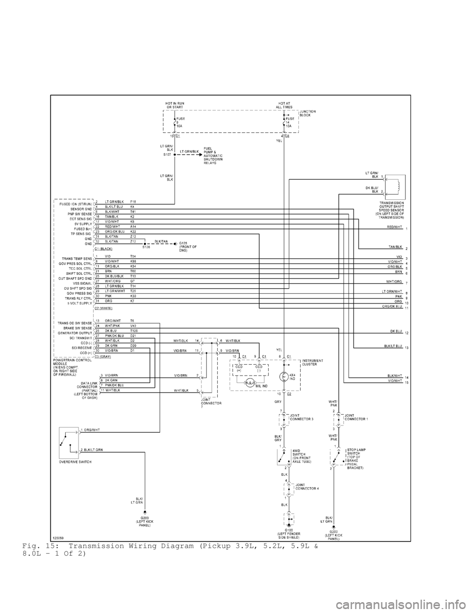
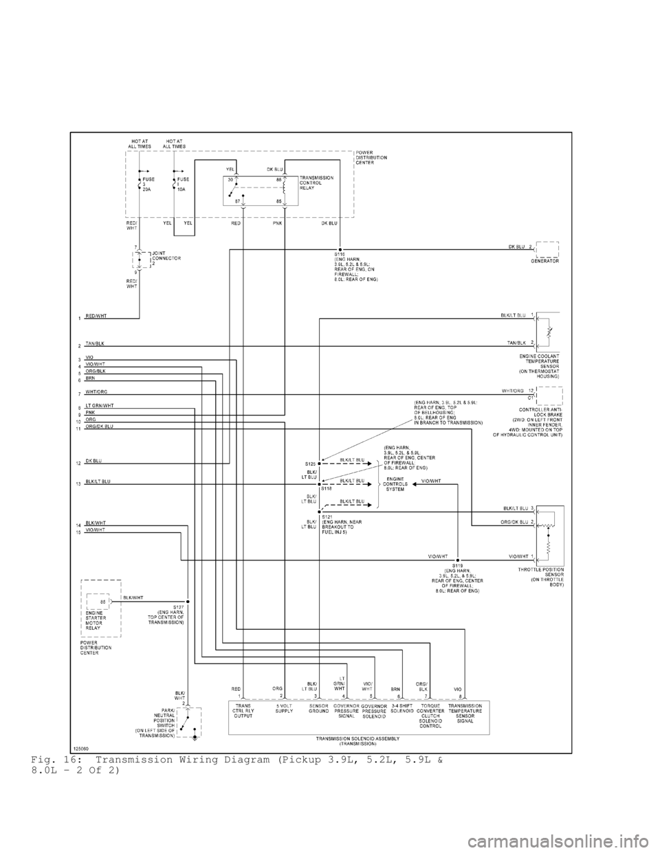
WIRING DIAGRAMS
Page 273 of 1691

Fig. 13: Transmission Wiring Diagram (Dakota)
Page 274 of 1691

Fig. 14: Transmission Wiring Diagram (Durango)
Page 275 of 1691

Fig. 15: Transmission Wiring Diagram (Pickup 3.9L, 5.2L, 5.9L &
8.0L - 1 Of 2)
Page 276 of 1691

Fig. 16: Transmission Wiring Diagram (Pickup 3.9L, 5.2L, 5.9L &
8.0L - 2 Of 2)