1999 DODGE RAM check engine
[x] Cancel search: check enginePage 931 of 1691
2) Disconnect drain tube from drain valve. Disconnect
electrical connector for Water-In-Fuel (WIF) sensor at bottom of fuel
filter/water separator. See Fig. 3.
3) Support canister for fuel filter/water separator and
remove canister nut from top of filter mounting head. See Fig. 3.
Remove canister with fuel filter/water separator and seal ring from
filter mounting head. Remove fuel filter/water separator from
canister.
4) Remove "O" ring from top of shaft inside the canister.
Remove bolts and drain valve from canister (if necessary).
5) Check the 2 probes inside the canister on end of WIF
sensor for contamination. Clean probes if contaminated. If
contamination cannot be removed from the probes, replace WIF sensor.
If replacing WIF sensor, remove WIF sensor and "O" ring from canister.
6) Fuel heater is located inside fuel filter housing. Heater
mounting plate, heating element, temperature sensor, and wiring
harness are serviced as an assembly. Disconnect heater electrical
connector from engine wiring harness near upper rear part of filter.
7) Disconnect electrical connector at end of 2-wire harness
before attempting to pass harness through filter header. Remove clip
retaining wires to connector. Remove wires from connector. Remove 3
fuel heater screws. Press on heater sealing grommet to remove heater
from filter canister header. Pass wire through hole in filter header.
Remove fuel heater.
Installation
1) Ensure inside of canister is clean. Using NEW "O" ring,
install WIF sensor on canister (if removed). Tighten WIF sensor to
specification. See TORQUE SPECIFICATIONS.
2) Install drain valve on canister (if removed). Tighten
drain valve-to-canister bolts to specification. See TORQUE
SPECIFICATIONS.
3) Install NEW "O" ring on shaft inside canister. Coat "O"
ring with diesel fuel. Install NEW fuel filter/water separator and NEW
seal ring in canister. Coat seal ring with diesel fuel.
NOTE: Canister for fuel filter/water separator should be filled
with diesel fuel before installing. If canister cannot be
filled with diesel fuel, low-pressure fuel lines must be bled
after installation.
CAUTION: When installing canister on filter mounting head, ensure tab
areas on outside of canister align with tabs on filter
mounting head. This must be done to prevent damage to
canister and filter mounting head.
4) Fill canister for fuel filter/water separator with diesel
fuel. Install canister with fuel filter/water separator on filter
mounting head. Ensure canister fully engages with filter mounting head
and tab areas on outside of canister align with tabs on filter
mounting head.
5) Install and tighten canister nut to specification. See
TORQUE SPECIFICATIONS.
6) To install remaining components, reverse removal
procedure. If canister was not filled with diesel fuel, bleed low-
pressure fuel lines before starting engine. See FUEL LINE BLEEDING
under FUEL SYSTEM. Start engine and check for fuel leaks.
FUEL TANK MODULE & IN-TANK FUEL FILTER
NOTE: In-tank fuel filter is located on bottom of fuel tank module
which also contains the fuel gauge sending unit. Fuel tank
module is mounted on top of fuel tank.
Page 937 of 1691
injection pump timing, cylinder No. 1 at TDC on compression
stroke and timing pin is engaged in machined hole on camshaft
gear.
Installation
1) Check pump mounting surfaces at pump and mounting flange
for nicks, cuts or damage. Check "O" ring surfaces for nicks, cuts or
damage. Clean injection pump mounting flange at gear housing. Clean
front of injection pump. Install new "O" ring on pump mounting area.
Apply clean engine oil to injection pump "O" ring only.
CAUTION: Ensure fuel injection pump drive gear-to-shaft mating
surfaces are clean and free of oil to provide proper seating
of fuel injection pump drive gear on shaft of fuel injection
pump.
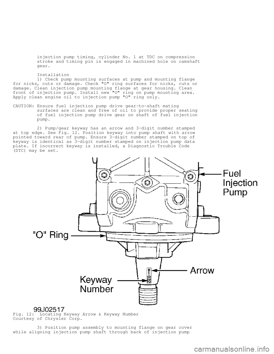
2) Pump/gear keyway has an arrow and 3-digit number stamped
at top edge. See Fig. 12. Position keyway into pump shaft with arrow
pointed toward rear of pump. Ensure 3-digit number stamped on top of
keyway is identical as 3-digit number stamped on injection pump data
plate. If incorrect keyway is installed, a Diagnostic Trouble Code
(DTC) may be set.
Fig. 12: Locating Keyway Arrow & Keyway Number
Courtesy of Chrysler Corp.
3) Position pump assembly to mounting flange on gear cover
while aligning injection pump shaft through back of injection pump
Page 966 of 1691
rotate crankshaft clockwise (viewed from front of engine) until
cylinder No. 1 is at Top Dead Center (TDC) on compression stroke and
timing mark on vibration damper aligns with "0" degree timing mark on
timing chain cover. DO NOT rotate crankshaft counterclockwise to align
timing marks. Go to next step.
3) Check position of slot in oil pump drive gear in cylinder
block. The slot in oil pump drive gear should be at approximately the
10 o'clock position. Rotate oil pump drive gear if necessary.
4) If installing a factory replacement distributor, go to
next step. If installing original or used distributor, remove camshaft
position sensor from distributor. See Fig. 13. Rotate distributor
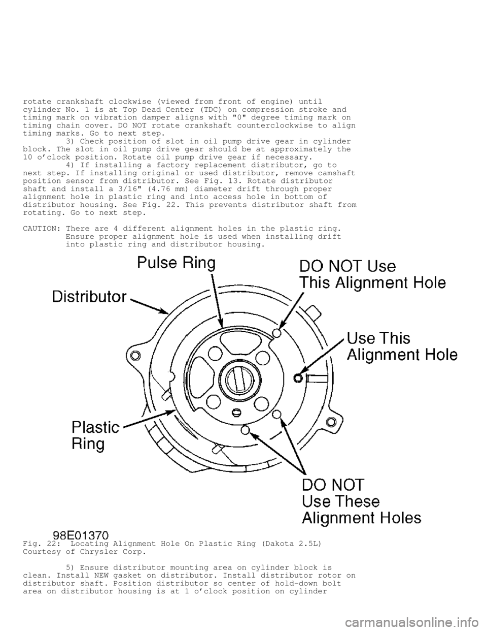
shaft and install a 3/16" (4.76 mm) diameter drift through proper
alignment hole in plastic ring and into access hole in bottom of
distributor housing. See Fig. 22. This prevents distributor shaft from
rotating. Go to next step.
CAUTION: There are 4 different alignment holes in the plastic ring.
Ensure proper alignment hole is used when installing drift
into plastic ring and distributor housing.
Fig. 22: Locating Alignment Hole On Plastic Ring (Dakota 2.5L)
Courtesy of Chrysler Corp.
5) Ensure distributor mounting area on cylinder block is
clean. Install NEW gasket on distributor. Install distributor rotor on
distributor shaft. Position distributor so center of hold-down bolt
area on distributor housing is at 1 o'clock position on cylinder
Page 968 of 1691
Installation
1) If engine has not been rotated after removing distributor,
go to next step. If engine was rotated after removing distributor,
rotate crankshaft clockwise (viewed from front of engine) until
cylinder No. 1 is at Top Dead Center (TDC) on compression stroke and
timing mark on vibration damper aligns with TDC timing mark on timing
chain cover. Go to next step.
2) Ensure distributor mounting area on cylinder block is
clean. Install NEW "O" ring on distributor if necessary. Apply light
coat of engine oil on "O" ring.
3) Position distributor rotor so it aligns with terminal for
cylinder No. 1 on distributor cap. Install distributor. Ensure
distributor engages with slot in oil pump drive gear. Install hold-
down clamp and distributor hold-down bolt. DO NOT tighten distributor
hold-down bolt at this time.
4) Rotate distributor until distributor rotor aligns with
cylinder No. 1 alignment mark on camshaft position sensor. See Fig. 23
. Tighten distributor hold-down bolt to specification. See TORQUE
SPECIFICATIONS. To install remaining components, reverse removal
procedure.
5) Base ignition timing is nonadjustable. Base ignition
timing and timing advance are controlled by the Powertrain Control
Module (PCM). Distributor position is used to determine the fuel
system synchronization. To check for correct distributor position and
fuel system synchronization, see FUEL SYSTEM SYNCHRONIZATION under
FUEL SYSTEM in ON-VEHICLE ADJUSTMENTS article.
IGNITION COIL
Removal & Installation (Dakota 2.5L)
Ignition coil is located on side of engine, near distributor.
Service procedure is primarily an unbolt and bolt-on procedure.
Tighten ignition coil retaining bolts or nuts to specification. See
TORQUE SPECIFICATIONS.
Removal & Installation (Dakota 3.9L, 5.2L & 5.9L, Durango &
Ram Van/Wagon)
1) Ignition coil is located on front of passenger's side
cylinder head. Disconnect spark plug wires and electrical connector
from ignition coil.
CAUTION: Ignition coil-to-cylinder head mounting bracket bolts hold
the idler pulley for the accessory drive belt, as these bolts
are under tension. If necessary to remove these bolts,
accessory drive belt must be removed first.
2) Remove ignition coil retaining bolts or nuts with ignition
coil from the ignition coil mounting bracket. DO NOT remove ignition
coil-to-cylinder head mounting bracket bolts, as these bolts are under
tension.
3) To install, reverse removal procedure. Tighten ignition
coil retaining bolts or nuts to specification. See TORQUE
SPECIFICATIONS.
Removal & Installation (Ram Pickup 3.9L, 5.2L & 5.9L)
1) On 3.9L, 5.2L and 5.9L with light-duty emissions, ignition
coil is located on front of passenger's side cylinder head. On 5.9L
with heavy-duty emissions, ignition coil is located on top of air
injection pump. On all models, disconnect spark plug wires and
electrical connector from ignition coil.
CAUTION: On 3.9L, 5.2L and 5.9L with light-duty emissions, ignition
coil-to-cylinder head mounting bracket bolts hold the idler
Page 971 of 1691
N - R EM OVE /IN STA LL/O VER HAU L
under FUEL SYSTEM. Disconnect negative battery cable. Ensure disconnect fitting and fuel lines are clean. Note location of releasetab and pull tab on disconnect fitting. See Fig. 24.
CAUTION: Release tab must be pressed downward before removing pull
tab, or pull tab will be damaged. 2) Press release tab downward. Use screwdriver to pry pull tab upward until pull tab separates from disconnect fitting. Removedisconnect fitting from fuel line. Inspect components for damage. Ifdisconnect fitting is damaged, entire assembly must be replaced, asonly pull tab may be replaced. 3) To install, ensure fuel line and disconnect fitting areclean. Lubricate fuel line and disconnect fitting with engine oil.Install disconnect fitting on fuel line until disconnect fittingbottoms on fuel line. 4) Install NEW pull tab until pull tab locks in disconnectfitting. DO NOT reuse old pull tab. Pull on fuel line and disconnectfitting to ensure components are properly locked together. Reconnectnegative battery cable. Start engine and check for leaks. Removal & Installation (Dual Tab)
1) Release fuel pressure. See FUEL SYSTEM PRESSURE RELEASE under FUEL SYSTEM. Disconnect negative battery cable. Ensuredisconnect fitting and fuel lines are clean. Note location of tabs ondisconnect fitting. See Fig. 24.
2) Squeeze both tabs against disconnect fitting. Pulldisconnect fitting from fuel line. The plastic retainer will remain onthe fuel system component being serviced. The "O" rings and spacerwill remain in the disconnect fitting. 3) Inspect components for damage. If disconnect fitting isdamaged, entire assembly must be replaced. The only component that maybe replaced is the plastic retainer. If plastic retainer must beremoved from fuel system component, carefully release the plasticretainer from the fuel system component using 2 screwdrivers. Inspectplastic retainer for cracks or damage. Replace plastic retainer ifdefective. 4) To install, ensure fuel line and disconnect fitting areclean. Lubricate fuel line and disconnect fitting with engine oil.Install disconnect fitting on fuel line until click sound is heard. 5) Pull on fuel line and disconnect fitting to ensurecomponents are properly locked together. Reconnect negative batterycable. Start engine and check for leaks. Removal & Installation (Plastic Retainer Ring)
1) Release fuel pressure. See FUEL SYSTEM PRESSURE RELEASE under FUEL SYSTEM. Disconnect negative battery cable. Ensuredisconnect fitting and fuel lines are clean. Note location of plasticretainer ring on disconnect fitting. See Fig. 24.
NOTE: Plastic retainer ring must be pressed evenly into disconnect fitting. If plastic retainer is not even, it will be difficult to remove disconnect fitting from fuel line. 2) Firmly push disconnect fitting toward the fuel line while pushing plastic retainer ring evenly into disconnect fitting. Withplastic retainer ring fully depressed, pull disconnect fitting fromfuel line. 3) Inspect components for damage. If disconnect fitting isdamaged, entire assembly must be replaced. 4) To install, ensure fuel line and disconnect fitting areclean. Lubricate fuel line and disconnect fitting with engine oil.Install disconnect fitting on fuel line until click sound is heard.
Page 972 of 1691
5) Pull on fuel line and disconnect fitting to ensure
components are properly locked together. Reconnect negative battery
cable. Start engine and check for leaks.
FUEL LINE AT FUEL RAIL
Removal & Installation (Dakota, Durango & Ram Pickup)
1) Release fuel pressure. See FUEL SYSTEM PRESSURE RELEASE
under FUEL SYSTEM. Disconnect negative battery cable.
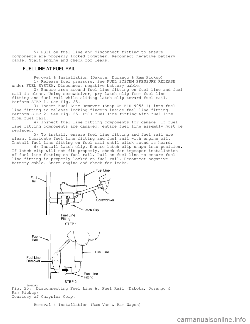
2) Ensure area around fuel line fitting on fuel line and fuel
rail is clean. Using screwdriver, pry latch clip from fuel line
fitting and fuel rail while sliding latch clip toward fuel rail.
Perform STEP 1. See Fig. 25.
3) Insert Fuel Line Remover (Snap-On FIH-9055-1) into fuel
line fitting to release locking fingers inside fuel line fitting.
Perform STEP 2. See Fig. 25. Pull fuel line fitting with fuel line
from fuel rail.
4) Inspect fuel line fitting components for damage. If fuel
line fitting components are damaged, entire fuel line assembly must be
replaced.
5) To install, ensure fuel line fitting and fuel rail are
clean. Lubricate fuel line fitting and fuel rail with engine oil.
Install fuel line fitting on fuel rail until click sound is heard.
6) Install latch clip. Ensure latch clip snaps into position.
If latch clip will not fit properly, check for improper installation
of fuel line fitting on fuel rail. Pull on fuel line to ensure fuel
line fitting is properly locked on fuel rail. Reconnect negative
battery cable. Start engine and check for leaks.
Fig. 25: Disconnecting Fuel Line At Fuel Rail (Dakota, Durango &
Ram Pickup)
Courtesy of Chrysler Corp.
Removal & Installation (Ram Van & Ram Wagon)
Page 973 of 1691
1) Release fuel pressure. See FUEL SYSTEM PRESSURE RELEASE
under FUEL SYSTEM. Disconnect negative battery cable.
2) Ensure area around fuel line fitting on fuel line and fuel
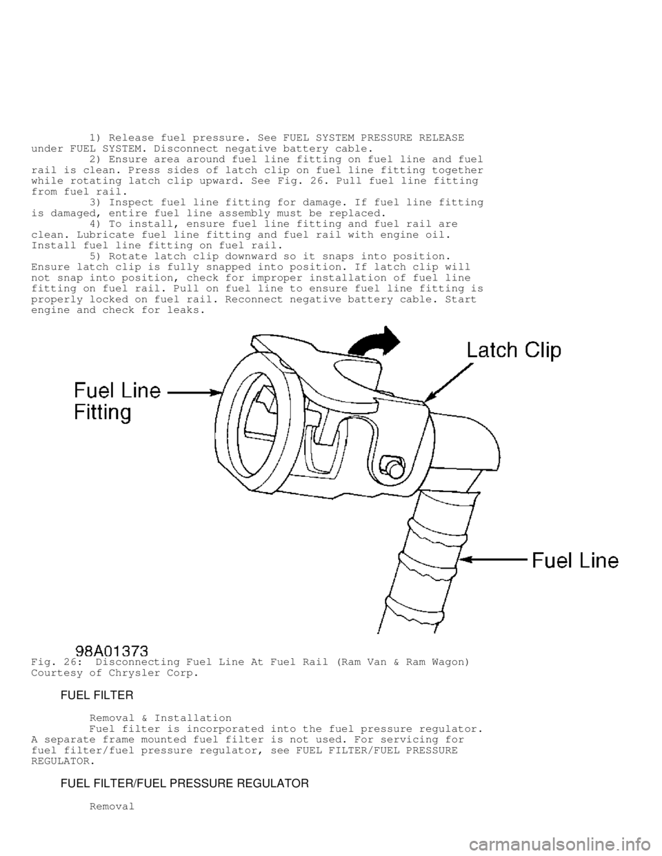
rail is clean. Press sides of latch clip on fuel line fitting together
while rotating latch clip upward. See Fig. 26. Pull fuel line fitting
from fuel rail.
3) Inspect fuel line fitting for damage. If fuel line fitting
is damaged, entire fuel line assembly must be replaced.
4) To install, ensure fuel line fitting and fuel rail are
clean. Lubricate fuel line fitting and fuel rail with engine oil.
Install fuel line fitting on fuel rail.
5) Rotate latch clip downward so it snaps into position.
Ensure latch clip is fully snapped into position. If latch clip will
not snap into position, check for improper installation of fuel line
fitting on fuel rail. Pull on fuel line to ensure fuel line fitting is
properly locked on fuel rail. Reconnect negative battery cable. Start
engine and check for leaks.
Fig. 26: Disconnecting Fuel Line At Fuel Rail (Ram Van & Ram Wagon)
Courtesy of Chrysler Corp.
FUEL FILTER
Removal & Installation
Fuel filter is incorporated into the fuel pressure regulator.
A separate frame mounted fuel filter is not used. For servicing for
fuel filter/fuel pressure regulator, see FUEL FILTER/FUEL PRESSURE
REGULATOR.
FUEL FILTER/FUEL PRESSURE REGULATOR
Removal
Page 985 of 1691
1) To install, reverse removal procedure. If installing small
vent tube and large fill tube on fuel tank, ensure fuel tank fittings
are clean.
2) Install disconnect fitting on fuel tank fitting until
disconnect fitting snaps onto fuel tank fitting. Pull on small vent
tube or and large fill tube to ensure disconnect fitting is locked on
fuel tank fitting. To verify proper installation of disconnect
fitting, ensure the distance between release sleeve and top of fuel
tank fitting is .50" (12.7 mm) on small vent tube or .25" (6.4 mm) o\
n
large fill tube. See Fig. 37.
3) Install fuel lines on fuel filter/fuel pressure regulator
on fuel pump module using proper procedure. See FUEL LINE DISCONNECT
FITTINGS under FUEL SYSTEM.
CAUTION: DO NOT overtighten fuel tank strap retaining nuts during
installation.
4) Tighten fuel tank strap retaining nuts to specification.
See TORQUE SPECIFICATIONS. To install remaining components, reverse
removal procedure. Start engine and check for fuel leaks.
Removal (Durango)
1) Fuel tank may be drained by removing vent hose from rear
of fuel tank, or by pumping fuel from fuel tank using the fuel pump if
fuel pump is operating. If removing vent hose from fuel tank to drain
the fuel, go to step 4). If using fuel pump to drain the fuel tank, go
to next step.
2) Disconnect fuel line from fuel rail. See FUEL LINE AT FUEL
RAIL under FUEL SYSTEM. Connect Fuel Hose (6541, 6539, 6631 or 6923)
for proper engine application at fuel line fitting on fuel rail. Place
remaining end of fuel hose in an approved gasoline container.
3) Connect scan tool to Data Link Connector (DLC). DLC is a
16-pin connector attached to bottom of driver's side of the instrument
panel, just to the right of the brake pedal. Using scan tool
manufacturer's instructions, activate the fuel pump and pump fuel from
fuel tank. Once fuel tank is empty, remove scan tool. Reinstall fuel
line on fuel rail using proper procedure. Go to step 5).
4) Release fuel pressure from fuel system. See FUEL SYSTEM
PRESSURE RELEASE. Ensure negative battery cable is disconnected.
Remove fuel tank cap to release any residual fuel tank pressure.
5) Raise and support vehicle. Remove necessary skid plates
for access to fuel tank. Disconnect vent and filler hose from rear of
fuel tank. If fuel tank was not previously drained, place drain hose
in vent hose fitting at rear of fuel tank. Drain fuel from fuel tank
into an approved gasoline container.
6) Support fuel tank with transmission jack. Remove fuel tank
strap retaining nuts. Position fuel tank straps toward outside of
vehicle. Slightly lower fuel tank. Ensure rear of fuel tank is higher
than front of fuel tank to prevent any spilling any remaining fuel in
fuel tank.
7) Disconnect fuel line from fuel filter/fuel pressure
regulator on fuel pump module using proper procedure for fuel line
disconnect fitting. See FUEL LINE DISCONNECT FITTINGS. Fuel pump
module is located on top of fuel tank. See Fig. 28. Disconnect
electrical connector at fuel pump module. Disconnect vapor line from
rollover valves on top of fuel tank and EVAP line from fuel pump
module. Lower fuel tank from vehicle.
CAUTION: DO NOT overtighten fuel tank strap retaining nuts during
installation.
Installation
1) To install, reverse removal procedure. Install fuel lines