1999 DODGE NEON coolant temperature
[x] Cancel search: coolant temperaturePage 879 of 1200

(14) Check the electrical connection at the knock
sensor (Fig. 41).
(15) Check the electrical connections at the cam-
shaft position sensor and engine coolant temperature
sensor (Fig. 42).
(16) Check the electrical connector at the Elec-
tronic EGR Transducer. Inspect the vacuum and back
pressure hoses at the solenoid and transducer for
leaks (Fig. 43).
(17) Inspect the electrical connections at the gen-
erator (Fig. 44). Check the generator belt for glazing
or damage.
Fig. 39 Duty Cycle Purge Solenoid
Fig. 40 Starter Motor and Ground Strap
Fig. 41 Knock Sensor
Fig. 42 Camshaft Position Sensor and Engine
Coolant Temperature Sensor
Fig. 43 Electronic EGR Transducer
14 - 38 FUEL SYSTEMPL
DIAGNOSIS AND TESTING (Continued)
Page 884 of 1200

(13) Inspect the air cleaner filter element. Replace
as necessary. Check the air induction system for
restrictions.
(14) Check the electrical connection at the knock
sensor (Fig. 64).
(15) Check the electrical connections at the cam-
shaft position sensor (Fig. 65) and engine coolant
temperature sensor (Fig. 66).
(16) Check the electrical connector at the Elec-
tronic EGR Transducer. Inspect the vacuum and back
pressure hoses at the solenoid and transducer for
leaks (Fig. 67).
(17) Inspect the electrical connections at the gen-
erator (Fig. 68). Check the generator belt for glazing
or damage.
Fig. 63 Starter Motor and Ground Strap
Fig. 64 Knock Sensor
Fig. 65 Camshaft Position Sensor
Fig. 66 Engine Coolant Temperature Sensor
Fig. 67 Electronic EGR Transducer
PLFUEL SYSTEM 14 - 43
DIAGNOSIS AND TESTING (Continued)
Page 888 of 1200

(7) Attach the other end of the jumper wire to
relay terminal 86. This activates the relay. The ohm-
meter should now show continuity between relay ter-
minals 87 and 30. The ohmmeter should not show
continuity between relay terminals 87A and 30.
(8) Disconnect jumper wires.
(9) Replace the relay if it did not pass the continu-
ity and resistance tests. If the relay passed the tests,
it operates properly. Check the remainder of the ASD
and fuel pump relay circuits. Refer to group 8W, Wir-
ing Diagrams.
CAMSHAFT AND CRANKSHAFT POSITION SENSOR
Refer to Group 8D, Ignition for Diagnosis and Test-
ing of Camshaft and Crankshaft Sensors.
ENGINE COOLANT TEMPERATURE SENSOR
(1) With the key off, disconnect wire harness con-
nector from coolant temperature sensor (Fig. 79) or
(Fig. 80).(2) Connect a high input impedance (digital) volt-
ohmmeter to terminals A and B (Fig. 81). The ohm-
meter should read as follows:
²Engine/Sensor at normal operating temperature
around 200ÉF should read approximately 700 to
1,000 ohms.
²Engine/Sensor at room temperature around 70ÉF
ohmmeter should read approximately 7,000 to 13,000
ohms.
(3) T
est the resistance of the wire harness between
the PCM 60-way connector terminal 28 and the sensor
harness connector. Also check for continuity between
PCM 60-way connector terminal 51 and the sensor har-
ness connector. Refer to Group 8W, Wiring diagrams for
circuit information. If the resistance is greater than 1
ohm, repair the wire harness as necessary.
HEATED OXYGEN SENSOR
Use an ohmmeter to test the heating element of
the oxygen sensors. Disconnect the electrical connec-
tor from each oxygen sensor. The white wires in the
sensor connector are the power and ground circuits
for the heater. Connect the ohmmeter test leads to
terminals of the white wires in the heated oxygen
sensor connector. Replace the heated oxygen sensor if
the resistance is not between 4 and 7 ohms.
IDLE AIR CONTROL (IAC) MOTOR TEST
To preform a complete test of IAC motor and its
circuitry, refer to DRB scan tool and the appropriate
Powertrain Diagnostics Procedures manual.
KNOCK SENSOR
The engine knock sensor is affected by a number of
factors. A few of these are: ignition timing, cylinder
pressure, fuel octane, etc. The knock sensor generates
an AC voltage whose amplitude increases with the
increase of engine knock. The knock sensor can be
tested with a digital voltmeter. The RMS voltage starts
Fig. 79 Engine Coolant Temperature Sensor
LocationÐSOHC
Fig. 80 Engine Coolant Temperature Sensor
LocationÐDOHC
Fig. 81 Engine Coolant Temperature Sensor
PLFUEL SYSTEM 14 - 47
DIAGNOSIS AND TESTING (Continued)
Page 897 of 1200

(3) Remove air cleaner element from front housing
(Fig. 106).
INSTALLATION
(1) Install air cleaner element into front housing.
(2) Rotate front of housing forward then lower into
place and locate tabs in slots. Fasten clasps on top of
air cleaner housing.
(3) Install air intake duct at air cleaner and intake
manifold.
ENGINE COOLANT TEMPERATURE SENSOR
The engine coolant temperature sensor threads
into the rear of the cylinder head (Fig. 107) or (Fig.
108).
REMOVAL
(1) With the engine cold, drain coolant until level
drops below cylinder head. Refer to Group 7, Cooling
System.
(2) Disconnect coolant sensor electrical connector.
(3) Remove coolant sensor.
INSTALLATION
(1) Install coolant sensor. Tighten sensor to 18
N´m (165 in. lbs.) torque.
(2) Attach electrical connector to sensor.
(3) Fill cooling system. Refer to Group 7, Cooling
System.
VEHICLE SPEED SENSOR
The vehicle speed sensor is located in the transmis-
sion extension housing (Fig. 109).
REMOVAL
(1) Disconnect electrical connector from sensor.
(2) Remove the sensor mounting bolt.
(3) Lift the sensor out of the transaxle extension
housing. Ensure the O-ring was removed with the
sensor.
Fig. 104 Air Intake Duct
Fig. 105 Removal/Installation of Air Inlet Duct
Fig. 106 Removal/Installation Air Cleaner Front
Housing and Element
Fig. 107 Engine Coolant Temperature SensorÐ
SOHC
14 - 56 FUEL SYSTEMPL
REMOVAL AND INSTALLATION (Continued)
Page 898 of 1200

INSTALLATION
The speed sensor gear meshes with a gear on the
output shaft.
(1) With O-ring in place, install sensor.
(2) Install mounting bolt.
(3) Connect electrical connector to sensor.
KNOCK SENSOR
For removal/installation procedures refer to Group
8D- Ignition System, Service Procedures.
SPECIFICATIONS
VECI LABEL
If anything differs between the specifications found
on the Vehicle Emission Control Information (VECI)
label and the following specifications, use specifica-
tions on VECI label. The VECI label is located in the
engine compartment.
TORQUE
DESCRIPTION TORQUE
Air Cleaner Wingnut..........1.5 N´m (15 in. lbs.)
Air Cleaner Mount. Stud-To-Thrott. Body .10 N´m (90
in. lbs.)
Crankshaft Position Sensor Mounting Bolts.8 N´m (70
in. lbs.)
Engine Coolant Temperature Sensor .18 N´m (165 in.
lbs.)
IAC Motor-To-Throttle Body Bolts .7 N´m (60 in. lbs.)
MAP/IAT Sensor..............2N´m(20in.lbs.)
MAP/IAT Sensor..............3N´m(30in.lbs.)
Oxygen Sensor...............28N´m(20ft.lbs.)
Powertrain Control Module (PCM) Mounting Screws.4
N´m (35 in. lbs.)
Throttle Cable Cover.........4.5 N´m (40 in. lbs.).
Throttle Body Mounting Bolts . .23 N´m (200 in. lbs.)
Throttle Position Sensor Mounting Screws .2 N´m (20
in. lbs.)
Vehicle Speed Sensor Mounting Bolt .2.2 N´m (20 in.
lbs.)
SPECIAL TOOLS
FUEL
Fig. 108 Engine Coolant Temperature SensorÐ
DOHCFig. 109 Vehicle Speed Sensor
Extractor C±4334Pressure Gauge Assembly C±4799±B
PLFUEL SYSTEM 14 - 57
REMOVAL AND INSTALLATION (Continued)
Page 1135 of 1200

GENERAL INFORMATION
INTRODUCTION
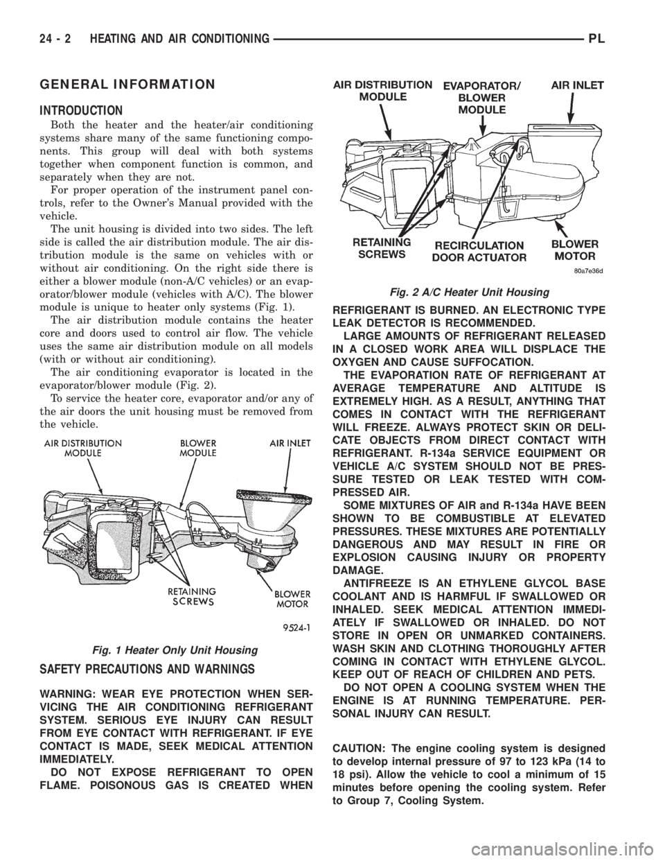
Both the heater and the heater/air conditioning
systems share many of the same functioning compo-
nents. This group will deal with both systems
together when component function is common, and
separately when they are not.
For proper operation of the instrument panel con-
trols, refer to the Owner's Manual provided with the
vehicle.
The unit housing is divided into two sides. The left
side is called the air distribution module. The air dis-
tribution module is the same on vehicles with or
without air conditioning. On the right side there is
either a blower module (non-A/C vehicles) or an evap-
orator/blower module (vehicles with A/C). The blower
module is unique to heater only systems (Fig. 1).
The air distribution module contains the heater
core and doors used to control air flow. The vehicle
uses the same air distribution module on all models
(with or without air conditioning).
The air conditioning evaporator is located in the
evaporator/blower module (Fig. 2).
To service the heater core, evaporator and/or any of
the air doors the unit housing must be removed from
the vehicle.
SAFETY PRECAUTIONS AND WARNINGS
WARNING: WEAR EYE PROTECTION WHEN SER-
VICING THE AIR CONDITIONING REFRIGERANT
SYSTEM. SERIOUS EYE INJURY CAN RESULT
FROM EYE CONTACT WITH REFRIGERANT. IF EYE
CONTACT IS MADE, SEEK MEDICAL ATTENTION
IMMEDIATELY.
DO NOT EXPOSE REFRIGERANT TO OPEN
FLAME. POISONOUS GAS IS CREATED WHENREFRIGERANT IS BURNED. AN ELECTRONIC TYPE
LEAK DETECTOR IS RECOMMENDED.
LARGE AMOUNTS OF REFRIGERANT RELEASED
IN A CLOSED WORK AREA WILL DISPLACE THE
OXYGEN AND CAUSE SUFFOCATION.
THE EVAPORATION RATE OF REFRIGERANT AT
AVERAGE TEMPERATURE AND ALTITUDE IS
EXTREMELY HIGH. AS A RESULT, ANYTHING THAT
COMES IN CONTACT WITH THE REFRIGERANT
WILL FREEZE. ALWAYS PROTECT SKIN OR DELI-
CATE OBJECTS FROM DIRECT CONTACT WITH
REFRIGERANT. R-134a SERVICE EQUIPMENT OR
VEHICLE A/C SYSTEM SHOULD NOT BE PRES-
SURE TESTED OR LEAK TESTED WITH COM-
PRESSED AIR.
SOME MIXTURES OF AIR and R-134a HAVE BEEN
SHOWN TO BE COMBUSTIBLE AT ELEVATED
PRESSURES. THESE MIXTURES ARE POTENTIALLY
DANGEROUS AND MAY RESULT IN FIRE OR
EXPLOSION CAUSING INJURY OR PROPERTY
DAMAGE.
ANTIFREEZE IS AN ETHYLENE GLYCOL BASE
COOLANT AND IS HARMFUL IF SWALLOWED OR
INHALED. SEEK MEDICAL ATTENTION IMMEDI-
ATELY IF SWALLOWED OR INHALED. DO NOT
STORE IN OPEN OR UNMARKED CONTAINERS.
WASH SKIN AND CLOTHING THOROUGHLY AFTER
COMING IN CONTACT WITH ETHYLENE GLYCOL.
KEEP OUT OF REACH OF CHILDREN AND PETS.
DO NOT OPEN A COOLING SYSTEM WHEN THE
ENGINE IS AT RUNNING TEMPERATURE. PER-
SONAL INJURY CAN RESULT.
CAUTION: The engine cooling system is designed
to develop internal pressure of 97 to 123 kPa (14 to
18 psi). Allow the vehicle to cool a minimum of 15
minutes before opening the cooling system. Refer
to Group 7, Cooling System.
Fig. 2 A/C Heater Unit Housing
Fig. 1 Heater Only Unit Housing
24 - 2 HEATING AND AIR CONDITIONINGPL
Page 1141 of 1200

(3) Close all doors, windows and vents to the pas-
senger compartment.
(4) Set Heater-A/C control to A/C, full heat, floor,
RECIRC. and high blower.
(5) Start the engine and hold the idle speed (1000
rpm). After the engine has reached running temper-
ature, allow the passenger compartment to heat up.
This will create the need for maximum refrigerant
flow into the evaporator.
(6) If the refrigerant charge is sufficient, discharge
(high pressure) gauge should read 965 to 2620 kPa
(140 to 380 psi). Suction (low pressure) gauge should
read 103 to 2417 kPa (15 to 35 psi). If system cannot
achieve proper pressure readings, replace the expan-
sion valve. If pressure is correct, proceed with test.
WARNING: PROTECT SKIN AND EYES FROM CON-
TACTING CO2 PERSONAL INJURY CAN RESULT.
(7) If suction side low pressure is within specified
range, freeze the expansion valve control head (Fig.
10) for 30 seconds. Use a super cold substance (liquid
CO2).Do not spray refrigerant on the expansion
valve for this test.Suction side low pressure should
drop to 34.5 kPa (5 psi) If not, replace expansion
valve.
(8) Allow expansion valve to thaw. The low pres-
sure gauge reading should stabilize at 103 to 241
kPa (15 to 35 psi). If not, replace expansion valve.
(9) When expansion valve test is complete, test
A/C overall performance. Refer to the Heater and A/C
Performance Test in this section. Remove all test
equipment before returning vehicle to use.
BLOWER MOTOR ELECTRICAL DIAGNOSIS
Refer to the Blower Motor Electrical System Diag-
nosis chart in this section. Also refer to Group 8W,
Wiring Diagrams for more information.
BLOWER MOTOR VIBRATION AND/OR NOISE
DIAGNOSIS
The resistor block supplies the blower motor with
varied voltage (low and middle speeds) or battery
voltage (high speed).
CAUTION: Stay clear of the blower motor and resis-
tor block (Hot). Do not operate the blower motor
with the resistor block removed from the heater-A/C
housing.
Refer to the Blower Motor Vibration/Noise chart
for diagnosis.
EVAPORATOR PROBE TEST
The work area and vehicle must be between 16É C
(60É F) and 32É C (90É F) when testing the switch.(1) Disconnect the three wire connector from the
evaporator probe lead located behind the glove box.
(2) Start engine and set A/C to low blower motor
speed, panel, full cool, and RECIRC.
(3) Using a voltmeter, check for battery voltage
between Pin 1 and 2. If no voltage is detected, there
is no power to the switch. Check wiring and fuses.
Refer to Group 8W, Wiring Diagrams for circuit diag-
nosis.
(4) Using a voltmeter, check for battery voltage
between Pin 1 and Pin 3. If no voltage is detected,
there is no voltage from the Powertrain Control Mod-
ule. Refer to Group 8W, Wiring Diagrams. If voltage
is OK, connect a jumper wire between Pin 1 and Pin
3. The compressor clutch should engage. If the clutch
engages, remove the jumper wire immediately and go
to Step 5. If the compressor clutch does not engage,
check the operation of the clutch and repair as nec-
essary.
(5) If compressor clutch engages, connect the evap-
orator probe 3-way connector. The compressor clutch
should engage or cycle depending on evaporator tem-
perature. If OK, go to Step 6. If not OK, replace the
clutch cycling switch.
(6) The engine running and the A/C set to:
²Blower motor on low speed
²Panel position
²Full cool
²RECIRC.
Close all doors and windows. Place a thermometer
in the center discharge vent.
(7) If the clutch does not begin to cycle off between
2É C to 7É C (35É F to 45É F), verify that the evapo-
rator probe is fully installed and not loose in evapo-
rator. If it is not properly installed, install probe and
retest outlet temperature. If the evaporator probe is
properly installed, replace the clutch cycling switch.
HEATER PERFORMANCE TEST
PRE-DIAGNOSTIC PREPARATIONS
Review Safety Precautions and Warnings in this
group before performing the following procedures.
Check the coolant level, drive belt tension, vacuum
line connections, radiator air flow and fan operation.
Start engine and allow to warm up to normal tem-
perature.
WARNING: DO NOT REMOVE RADIATOR CAP
WHEN ENGINE IS HOT, PERSONAL INJURY CAN
RESULT.
If vehicle has been run recently, wait 15 minutes
before removing cap. Place a rag over the cap and
turn it to the first safety stop. Allow pressure to
escape through the overflow tube. When the system
stabilizes, remove the cap completely.
24 - 8 HEATING AND AIR CONDITIONINGPL
DIAGNOSIS AND TESTING (Continued)
Page 1144 of 1200

MAXIMUM HEATER OUTPUT: TEST AND
ACTION
Engine coolant is provided to the heater system by
two 16 mm (5/8 inch inside diameter) heater hoses.
With engine idling at normal running temperature,
set the control to maximum heat, floor, and high
blower setting. Using a test thermometer, check the
air temperature coming from the floor outlets, refer
to Temperature Reference Table.
If the floor outlet air temperature is insufficient,
refer to Group 7, Cooling Systems for specifications.
Both heater hoses should be HOT to the touch (cool-
ant return hose should be slightly cooler than the
supply hose). If coolant return hose is much cooler
than the supply hose, locate and repair engine cool-
ant flow obstruction in heater system.
POSSIBLE LOCATIONS OR CAUSE OF
OBSTRUCTED COOLANT FLOW
(1) Pinched or kinked heater hoses.
(2) Improper heater hose routing.
(3) Plugged heater hoses or supply and return
ports at cooling system connections, refer to Group 7,
Cooling System.(4) Plugged heater core.
(5) Air locked heater core.
(6) If coolant flow is verified and outlet tempera-
ture is insufficient, a mechanical problem may exist.
POSSIBLE LOCATION OR CAUSE OF
INSUFFICIENT HEAT
(1) Obstructed cowl air intake.
(2) Obstructed heater system outlets.
(3) Blend-air door not functioning properly.
TEMPERATURE CONTROL
If temperature cannot be adjusted with the TEMP
lever on the control panel, the following could require
service:
(1) Blend-air door binding.
(2) Faulty blend-air door cable.
(3) Improper engine coolant temperature.
(4) Faulty Instrument Panel Control.
LOW PRESSURE CUT-OFF SWITCH
The work area must not be below 21ÉC (70ÉF) to
test the compressor clutch circuit.
(1) With gear selector in park or neutral and park
brake set, start engine and allow to idle.
(2) Raise hood and disconnect low pressure cut off
switch connector boot.
(3) Using a suitable jumper wire, jump across the
terminals inside wire connector boot.
(4) If the compressor clutch does not engage, the
cycling clutch switch, wiring, relay, or fuse can be
defective. Refer to Group 8W, Wiring Diagrams.
(5) If clutch engages, connect manifold gauge set.
Read low pressure gauge. At pressure above 97 kPa
(14 psi) and above, low pressure out off switch will
complete the clutch circuit. If the low pressure gauge
reads below 140 kPa (20 psi), the system is low on
refrigerant charge or empty due to a leak. Refer to
Service±Procedures, System Leak Checking in this
section.
(6) Install connector boot on switch and repeat
Step 3. If the clutch does not engage, replace the low
pressure cut off switch.
SYSTEM CHARGE LEVEL TEST
The procedure below should be used to check
and/or fill the refrigerant charge in the air condition-
ing system.
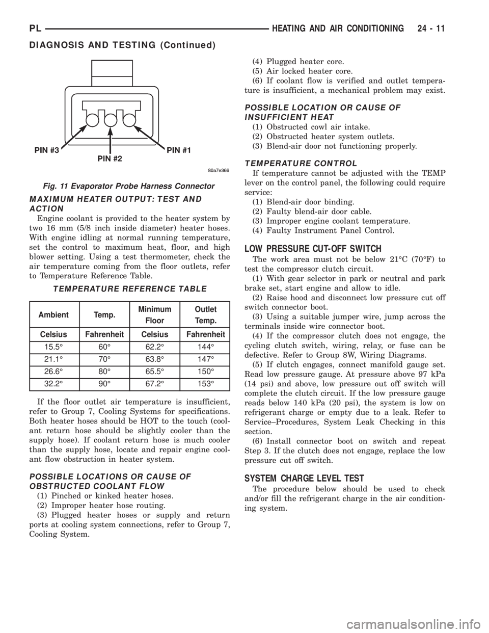
Fig. 11 Evaporator Probe Harness Connector
TEMPERATURE REFERENCE TABLE
Ambient Temp.Minimum
FloorOutlet
Temp.
Celsius Fahrenheit Celsius Fahrenheit
15.5É 60É 62.2É 144É
21.1É 70É 63.8É 147É
26.6É 80É 65.5É 150É
32.2É 90É 67.2É 153É
PLHEATING AND AIR CONDITIONING 24 - 11
DIAGNOSIS AND TESTING (Continued)