1999 DODGE NEON fuses
[x] Cancel search: fusesPage 289 of 1200
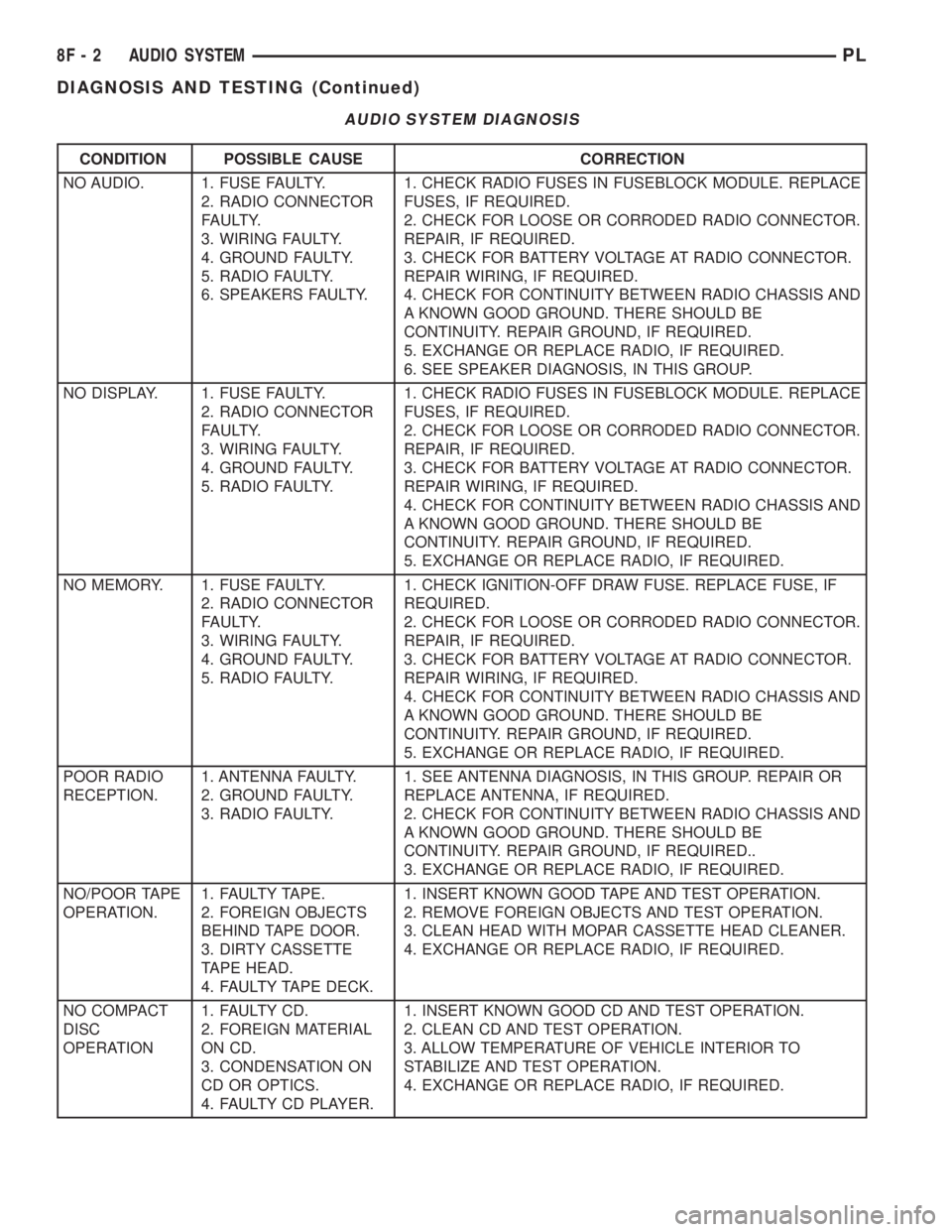
AUDIO SYSTEM DIAGNOSIS
CONDITION POSSIBLE CAUSE CORRECTION
NO AUDIO. 1. FUSE FAULTY.
2. RADIO CONNECTOR
FAULTY.
3. WIRING FAULTY.
4. GROUND FAULTY.
5. RADIO FAULTY.
6. SPEAKERS FAULTY.1. CHECK RADIO FUSES IN FUSEBLOCK MODULE. REPLACE
FUSES, IF REQUIRED.
2. CHECK FOR LOOSE OR CORRODED RADIO CONNECTOR.
REPAIR, IF REQUIRED.
3. CHECK FOR BATTERY VOLTAGE AT RADIO CONNECTOR.
REPAIR WIRING, IF REQUIRED.
4. CHECK FOR CONTINUITY BETWEEN RADIO CHASSIS AND
A KNOWN GOOD GROUND. THERE SHOULD BE
CONTINUITY. REPAIR GROUND, IF REQUIRED.
5. EXCHANGE OR REPLACE RADIO, IF REQUIRED.
6. SEE SPEAKER DIAGNOSIS, IN THIS GROUP.
NO DISPLAY. 1. FUSE FAULTY.
2. RADIO CONNECTOR
FAULTY.
3. WIRING FAULTY.
4. GROUND FAULTY.
5. RADIO FAULTY.1. CHECK RADIO FUSES IN FUSEBLOCK MODULE. REPLACE
FUSES, IF REQUIRED.
2. CHECK FOR LOOSE OR CORRODED RADIO CONNECTOR.
REPAIR, IF REQUIRED.
3. CHECK FOR BATTERY VOLTAGE AT RADIO CONNECTOR.
REPAIR WIRING, IF REQUIRED.
4. CHECK FOR CONTINUITY BETWEEN RADIO CHASSIS AND
A KNOWN GOOD GROUND. THERE SHOULD BE
CONTINUITY. REPAIR GROUND, IF REQUIRED.
5. EXCHANGE OR REPLACE RADIO, IF REQUIRED.
NO MEMORY. 1. FUSE FAULTY.
2. RADIO CONNECTOR
FAULTY.
3. WIRING FAULTY.
4. GROUND FAULTY.
5. RADIO FAULTY.1. CHECK IGNITION-OFF DRAW FUSE. REPLACE FUSE, IF
REQUIRED.
2. CHECK FOR LOOSE OR CORRODED RADIO CONNECTOR.
REPAIR, IF REQUIRED.
3. CHECK FOR BATTERY VOLTAGE AT RADIO CONNECTOR.
REPAIR WIRING, IF REQUIRED.
4. CHECK FOR CONTINUITY BETWEEN RADIO CHASSIS AND
A KNOWN GOOD GROUND. THERE SHOULD BE
CONTINUITY. REPAIR GROUND, IF REQUIRED.
5. EXCHANGE OR REPLACE RADIO, IF REQUIRED.
POOR RADIO
RECEPTION.1. ANTENNA FAULTY.
2. GROUND FAULTY.
3. RADIO FAULTY.1. SEE ANTENNA DIAGNOSIS, IN THIS GROUP. REPAIR OR
REPLACE ANTENNA, IF REQUIRED.
2. CHECK FOR CONTINUITY BETWEEN RADIO CHASSIS AND
A KNOWN GOOD GROUND. THERE SHOULD BE
CONTINUITY. REPAIR GROUND, IF REQUIRED..
3. EXCHANGE OR REPLACE RADIO, IF REQUIRED.
NO/POOR TAPE
OPERATION.1. FAULTY TAPE.
2. FOREIGN OBJECTS
BEHIND TAPE DOOR.
3. DIRTY CASSETTE
TAPE HEAD.
4. FAULTY TAPE DECK.1. INSERT KNOWN GOOD TAPE AND TEST OPERATION.
2. REMOVE FOREIGN OBJECTS AND TEST OPERATION.
3. CLEAN HEAD WITH MOPAR CASSETTE HEAD CLEANER.
4. EXCHANGE OR REPLACE RADIO, IF REQUIRED.
NO COMPACT
DISC
OPERATION1. FAULTY CD.
2. FOREIGN MATERIAL
ON CD.
3. CONDENSATION ON
CD OR OPTICS.
4. FAULTY CD PLAYER.1. INSERT KNOWN GOOD CD AND TEST OPERATION.
2. CLEAN CD AND TEST OPERATION.
3. ALLOW TEMPERATURE OF VEHICLE INTERIOR TO
STABILIZE AND TEST OPERATION.
4. EXCHANGE OR REPLACE RADIO, IF REQUIRED.
8F - 2 AUDIO SYSTEMPL
DIAGNOSIS AND TESTING (Continued)
Page 330 of 1200
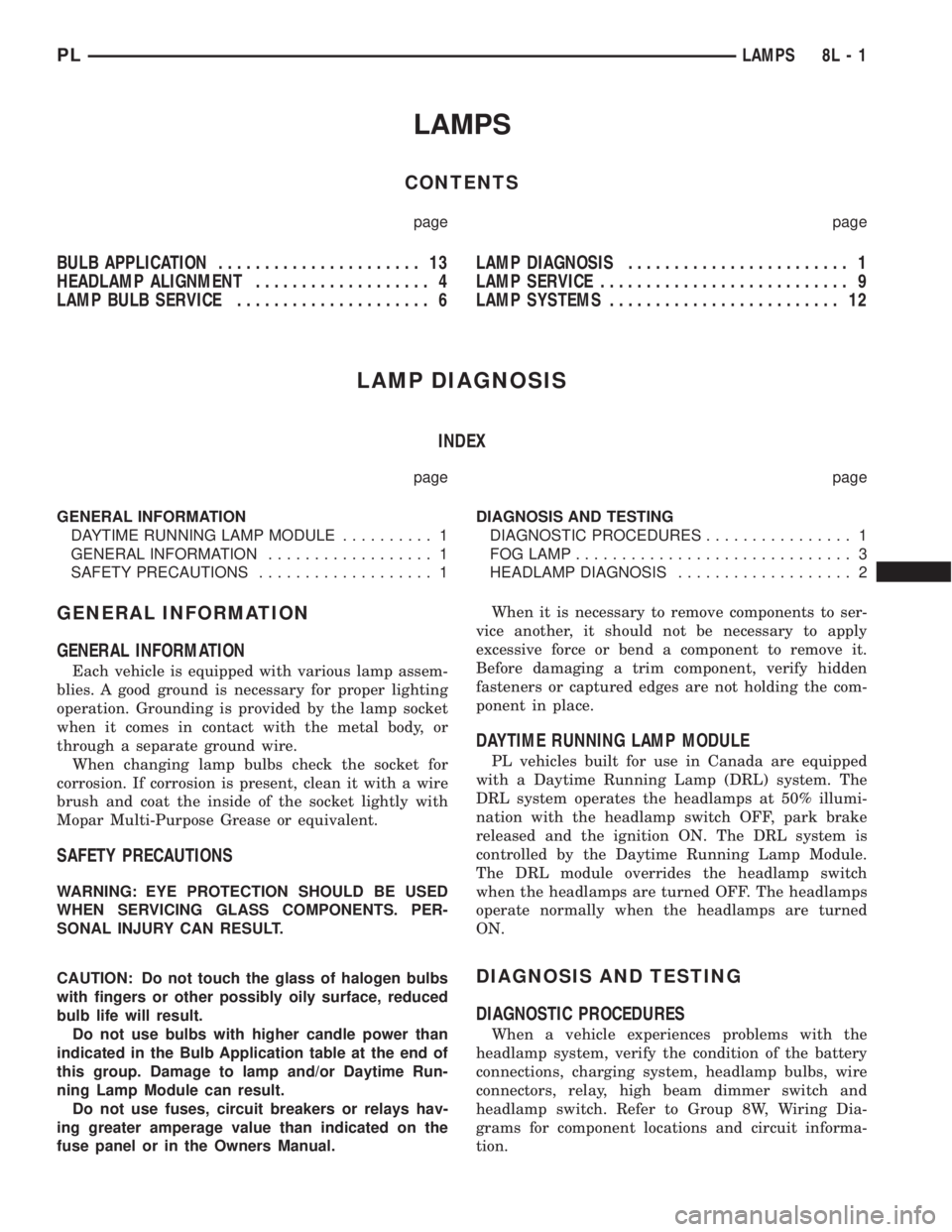
LAMPS
CONTENTS
page page
BULB APPLICATION...................... 13
HEADLAMP ALIGNMENT................... 4
LAMP BULB SERVICE..................... 6LAMP DIAGNOSIS........................ 1
LAMP SERVICE........................... 9
LAMP SYSTEMS......................... 12
LAMP DIAGNOSIS
INDEX
page page
GENERAL INFORMATION
DAYTIME RUNNING LAMP MODULE.......... 1
GENERAL INFORMATION.................. 1
SAFETY PRECAUTIONS................... 1DIAGNOSIS AND TESTING
DIAGNOSTIC PROCEDURES................ 1
FOG LAMP.............................. 3
HEADLAMP DIAGNOSIS................... 2
GENERAL INFORMATION
GENERAL INFORMATION
Each vehicle is equipped with various lamp assem-
blies. A good ground is necessary for proper lighting
operation. Grounding is provided by the lamp socket
when it comes in contact with the metal body, or
through a separate ground wire.
When changing lamp bulbs check the socket for
corrosion. If corrosion is present, clean it with a wire
brush and coat the inside of the socket lightly with
Mopar Multi-Purpose Grease or equivalent.
SAFETY PRECAUTIONS
WARNING: EYE PROTECTION SHOULD BE USED
WHEN SERVICING GLASS COMPONENTS. PER-
SONAL INJURY CAN RESULT.
CAUTION: Do not touch the glass of halogen bulbs
with fingers or other possibly oily surface, reduced
bulb life will result.
Do not use bulbs with higher candle power than
indicated in the Bulb Application table at the end of
this group. Damage to lamp and/or Daytime Run-
ning Lamp Module can result.
Do not use fuses, circuit breakers or relays hav-
ing greater amperage value than indicated on the
fuse panel or in the Owners Manual.When it is necessary to remove components to ser-
vice another, it should not be necessary to apply
excessive force or bend a component to remove it.
Before damaging a trim component, verify hidden
fasteners or captured edges are not holding the com-
ponent in place.
DAYTIME RUNNING LAMP MODULE
PL vehicles built for use in Canada are equipped
with a Daytime Running Lamp (DRL) system. The
DRL system operates the headlamps at 50% illumi-
nation with the headlamp switch OFF, park brake
released and the ignition ON. The DRL system is
controlled by the Daytime Running Lamp Module.
The DRL module overrides the headlamp switch
when the headlamps are turned OFF. The headlamps
operate normally when the headlamps are turned
ON.
DIAGNOSIS AND TESTING
DIAGNOSTIC PROCEDURES
When a vehicle experiences problems with the
headlamp system, verify the condition of the battery
connections, charging system, headlamp bulbs, wire
connectors, relay, high beam dimmer switch and
headlamp switch. Refer to Group 8W, Wiring Dia-
grams for component locations and circuit informa-
tion.
PLLAMPS 8L - 1
Page 331 of 1200
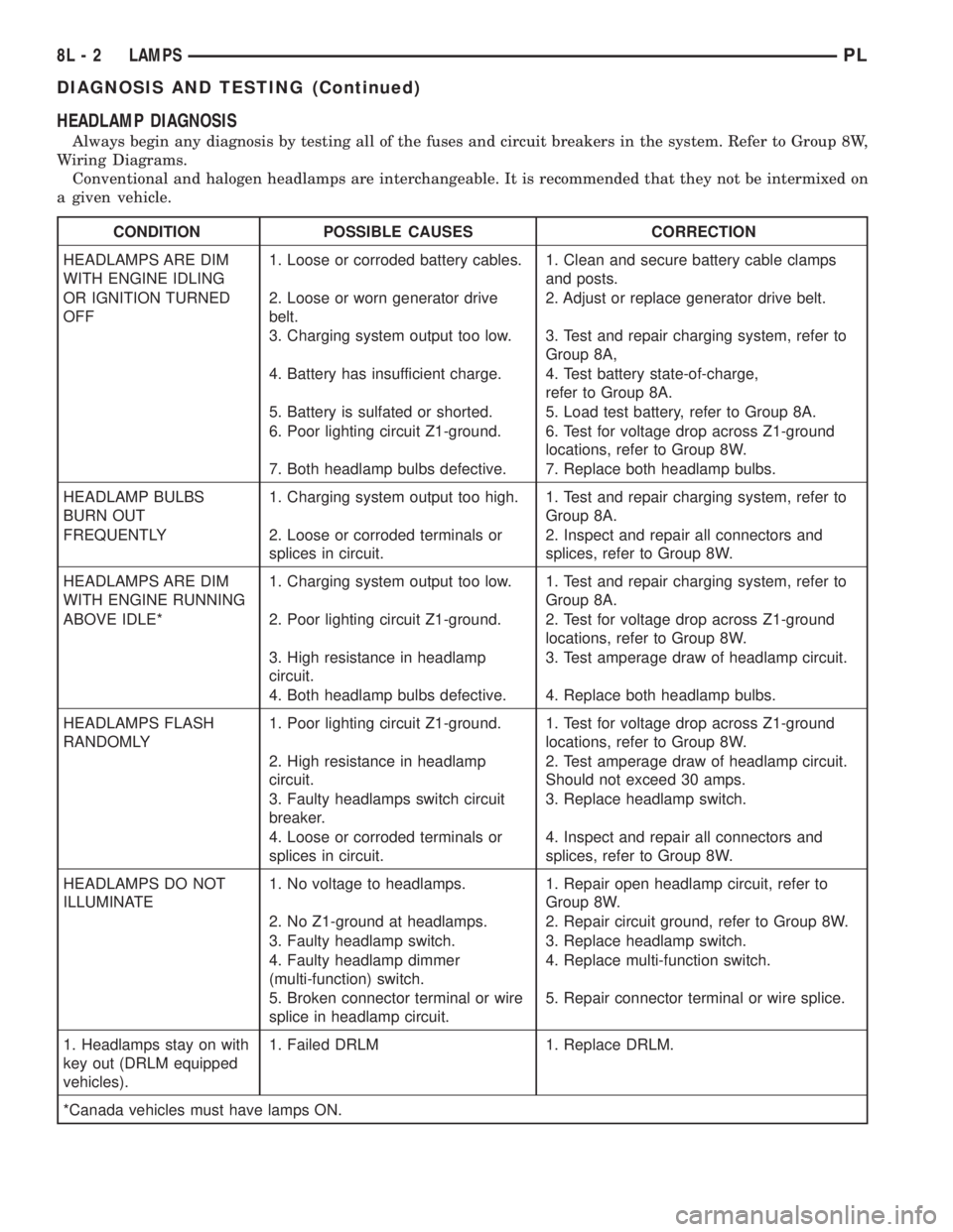
HEADLAMP DIAGNOSIS
Always begin any diagnosis by testing all of the fuses and circuit breakers in the system. Refer to Group 8W,
Wiring Diagrams.
Conventional and halogen headlamps are interchangeable. It is recommended that they not be intermixed on
a given vehicle.
CONDITION POSSIBLE CAUSES CORRECTION
HEADLAMPS ARE DIM
WITH ENGINE IDLING1. Loose or corroded battery cables. 1. Clean and secure battery cable clamps
and posts.
OR IGNITION TURNED
OFF2. Loose or worn generator drive
belt.2. Adjust or replace generator drive belt.
3. Charging system output too low. 3. Test and repair charging system, refer to
Group 8A,
4. Battery has insufficient charge. 4. Test battery state-of-charge,
refer to Group 8A.
5. Battery is sulfated or shorted. 5. Load test battery, refer to Group 8A.
6. Poor lighting circuit Z1-ground. 6. Test for voltage drop across Z1-ground
locations, refer to Group 8W.
7. Both headlamp bulbs defective. 7. Replace both headlamp bulbs.
HEADLAMP BULBS
BURN OUT1. Charging system output too high. 1. Test and repair charging system, refer to
Group 8A.
FREQUENTLY 2. Loose or corroded terminals or
splices in circuit.2. Inspect and repair all connectors and
splices, refer to Group 8W.
HEADLAMPS ARE DIM
WITH ENGINE RUNNING1. Charging system output too low. 1. Test and repair charging system, refer to
Group 8A.
ABOVE IDLE* 2. Poor lighting circuit Z1-ground. 2. Test for voltage drop across Z1-ground
locations, refer to Group 8W.
3. High resistance in headlamp
circuit.3. Test amperage draw of headlamp circuit.
4. Both headlamp bulbs defective. 4. Replace both headlamp bulbs.
HEADLAMPS FLASH
RANDOMLY1. Poor lighting circuit Z1-ground. 1. Test for voltage drop across Z1-ground
locations, refer to Group 8W.
2. High resistance in headlamp
circuit.2. Test amperage draw of headlamp circuit.
Should not exceed 30 amps.
3. Faulty headlamps switch circuit
breaker.3. Replace headlamp switch.
4. Loose or corroded terminals or
splices in circuit.4. Inspect and repair all connectors and
splices, refer to Group 8W.
HEADLAMPS DO NOT
ILLUMINATE1. No voltage to headlamps. 1. Repair open headlamp circuit, refer to
Group 8W.
2. No Z1-ground at headlamps. 2. Repair circuit ground, refer to Group 8W.
3. Faulty headlamp switch. 3. Replace headlamp switch.
4. Faulty headlamp dimmer
(multi-function) switch.4. Replace multi-function switch.
5. Broken connector terminal or wire
splice in headlamp circuit.5. Repair connector terminal or wire splice.
1. Headlamps stay on with
key out (DRLM equipped
vehicles).1. Failed DRLM 1. Replace DRLM.
*Canada vehicles must have lamps ON.
8L - 2 LAMPSPL
DIAGNOSIS AND TESTING (Continued)
Page 366 of 1200
Instrument Panel and Systems for removal proce-
dures.
(2) Turn the ignition switch ON.
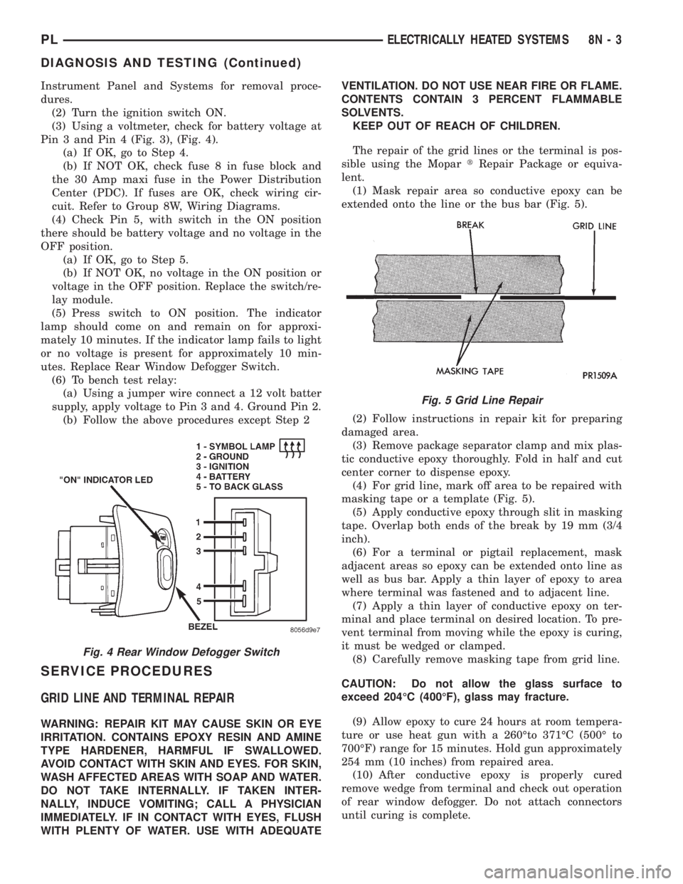
(3) Using a voltmeter, check for battery voltage at
Pin 3 and Pin 4 (Fig. 3), (Fig. 4).
(a) If OK, go to Step 4.
(b) If NOT OK, check fuse 8 in fuse block and
the 30 Amp maxi fuse in the Power Distribution
Center (PDC). If fuses are OK, check wiring cir-
cuit. Refer to Group 8W, Wiring Diagrams.
(4) Check Pin 5, with switch in the ON position
there should be battery voltage and no voltage in the
OFF position.
(a) If OK, go to Step 5.
(b) If NOT OK, no voltage in the ON position or
voltage in the OFF position. Replace the switch/re-
lay module.
(5) Press switch to ON position. The indicator
lamp should come on and remain on for approxi-
mately 10 minutes. If the indicator lamp fails to light
or no voltage is present for approximately 10 min-
utes. Replace Rear Window Defogger Switch.
(6) To bench test relay:
(a) Using a jumper wire connect a 12 volt batter
supply, apply voltage to Pin 3 and 4. Ground Pin 2.
(b) Follow the above procedures except Step 2
SERVICE PROCEDURES
GRID LINE AND TERMINAL REPAIR
WARNING: REPAIR KIT MAY CAUSE SKIN OR EYE
IRRITATION. CONTAINS EPOXY RESIN AND AMINE
TYPE HARDENER, HARMFUL IF SWALLOWED.
AVOID CONTACT WITH SKIN AND EYES. FOR SKIN,
WASH AFFECTED AREAS WITH SOAP AND WATER.
DO NOT TAKE INTERNALLY. IF TAKEN INTER-
NALLY, INDUCE VOMITING; CALL A PHYSICIAN
IMMEDIATELY. IF IN CONTACT WITH EYES, FLUSH
WITH PLENTY OF WATER. USE WITH ADEQUATEVENTILATION. DO NOT USE NEAR FIRE OR FLAME.
CONTENTS CONTAIN 3 PERCENT FLAMMABLE
SOLVENTS.
KEEP OUT OF REACH OF CHILDREN.
The repair of the grid lines or the terminal is pos-
sible using the MopartRepair Package or equiva-
lent.
(1) Mask repair area so conductive epoxy can be
extended onto the line or the bus bar (Fig. 5).
(2) Follow instructions in repair kit for preparing
damaged area.
(3) Remove package separator clamp and mix plas-
tic conductive epoxy thoroughly. Fold in half and cut
center corner to dispense epoxy.
(4) For grid line, mark off area to be repaired with
masking tape or a template (Fig. 5).
(5) Apply conductive epoxy through slit in masking
tape. Overlap both ends of the break by 19 mm (3/4
inch).
(6) For a terminal or pigtail replacement, mask
adjacent areas so epoxy can be extended onto line as
well as bus bar. Apply a thin layer of epoxy to area
where terminal was fastened and to adjacent line.
(7) Apply a thin layer of conductive epoxy on ter-
minal and place terminal on desired location. To pre-
vent terminal from moving while the epoxy is curing,
it must be wedged or clamped.
(8) Carefully remove masking tape from grid line.
CAUTION: Do not allow the glass surface to
exceed 204ÉC (400ÉF), glass may fracture.
(9) Allow epoxy to cure 24 hours at room tempera-
ture or use heat gun with a 260Éto 371ÉC (500É to
700ÉF) range for 15 minutes. Hold gun approximately
254 mm (10 inches) from repaired area.
(10) After conductive epoxy is properly cured
remove wedge from terminal and check out operation
of rear window defogger. Do not attach connectors
until curing is complete.
Fig. 4 Rear Window Defogger Switch
Fig. 5 Grid Line Repair
PLELECTRICALLY HEATED SYSTEMS 8N - 3
DIAGNOSIS AND TESTING (Continued)
Page 368 of 1200
ELECTRICALLY HEATED SYSTEMS
CONTENTS
page page
DIAGNOSIS AND TESTING
REAR WINDOW DEFOGGER SWITCH....... 1REMOVAL AND INSTALLATION
REAR WINDOW DEFOGGER AND/OR REAR
FOG LAMP SWITCH................... 2
DIAGNOSIS AND TESTING
REAR WINDOW DEFOGGER SWITCH
The rear window defogger switch may be tested in-
vehicle or bench tested. In vehicle testing is accom-
plished in the following manner:
(1) Remove the switch from the instrument panel
but leave the switch connected, refer to Group 8E,
Instrument Panel and Systems for removal proce-
dures.
(2) Turn the ignition switch ON.
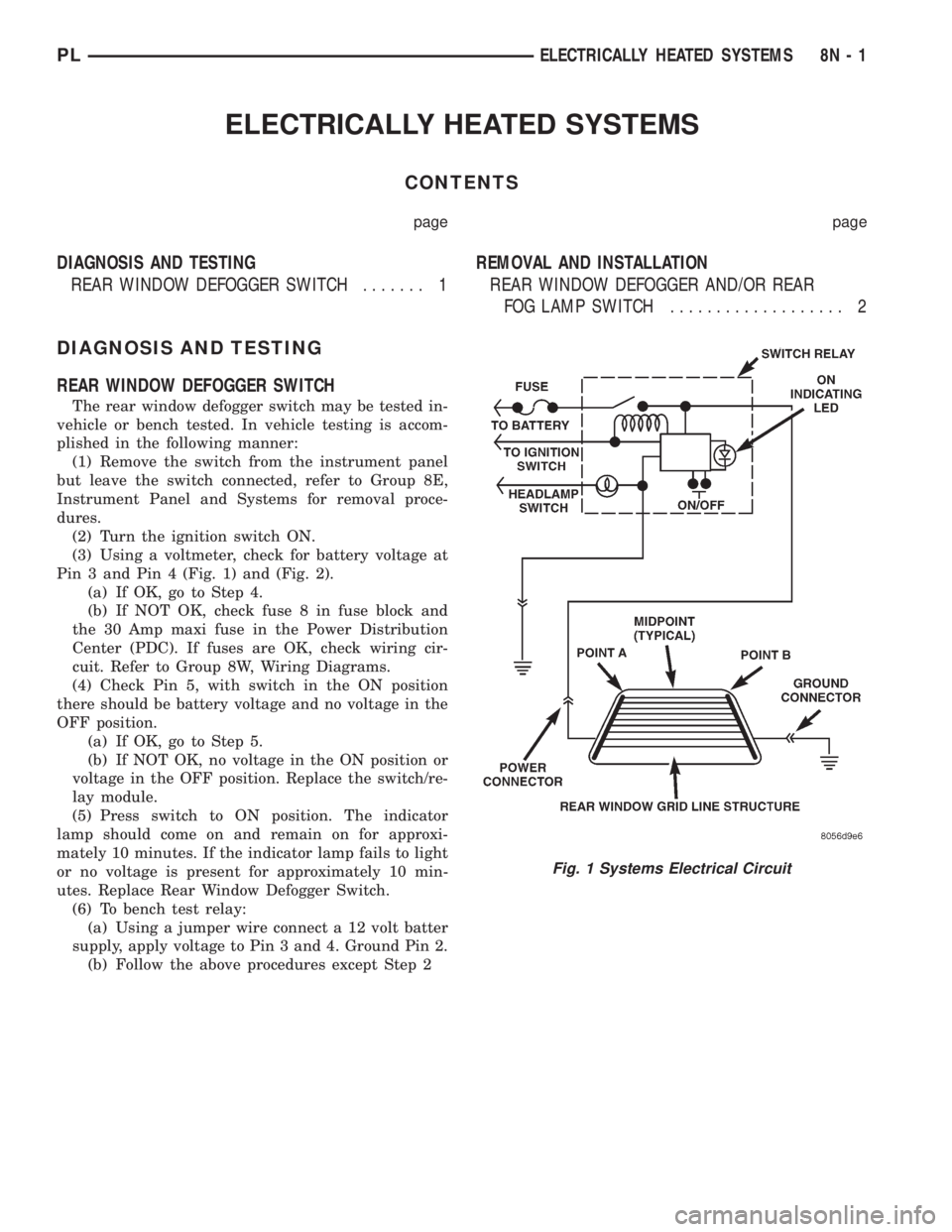
(3) Using a voltmeter, check for battery voltage at
Pin 3 and Pin 4 (Fig. 1) and (Fig. 2).
(a) If OK, go to Step 4.
(b) If NOT OK, check fuse 8 in fuse block and
the 30 Amp maxi fuse in the Power Distribution
Center (PDC). If fuses are OK, check wiring cir-
cuit. Refer to Group 8W, Wiring Diagrams.
(4) Check Pin 5, with switch in the ON position
there should be battery voltage and no voltage in the
OFF position.
(a) If OK, go to Step 5.
(b) If NOT OK, no voltage in the ON position or
voltage in the OFF position. Replace the switch/re-
lay module.
(5) Press switch to ON position. The indicator
lamp should come on and remain on for approxi-
mately 10 minutes. If the indicator lamp fails to light
or no voltage is present for approximately 10 min-
utes. Replace Rear Window Defogger Switch.
(6) To bench test relay:
(a) Using a jumper wire connect a 12 volt batter
supply, apply voltage to Pin 3 and 4. Ground Pin 2.
(b) Follow the above procedures except Step 2
Fig. 1 Systems Electrical Circuit
PLELECTRICALLY HEATED SYSTEMS 8N - 1
Page 374 of 1200
parking lamps out put. Press the panic button and
check for a voltage pulse (Fig. 2).
(2) If no voltage pulse is measured, replace the
receiver. If voltage OK, repair circuit to the parking
lamps as necessary.
(3) Connect the meter to Pin 5 of the black connec-
tor and to ground to test head lamps out put. Press
the panic button and check for a voltage pulse (Fig.
2).
(4) If no voltage pulse is measured, replace the
receiver. If voltage OK, repair circuit to the head
lamps as necessary.
REMOTE KEYLESS ENTRY SYSTEM
When trouble shooting problems with the Remote
Keyless Entry System, always verify that the power
door lock/unlock switches are functional. If the doors
do not lock/unlock refer to Group 8W, Wiring Dia-
gram for Pin and wiring locations.
If the following items do not work:
²Remote keyless entry system
²Radio/clock
²Door lock switches
A blown fuse is the probable cause. Check fuses 2,
3 and 11 in the fuse block. To check for a blown fuse,
pull the fuse out slightly, but maintain contact
between the fuse terminals and the terminals in fuse
block. Using the voltmeter probe, check both termi-
nals for 12 volts. If only one terminal measures bat-
tery voltage, the circuit breaker is defective and must
be replaced. If neither terminal measures battery
voltage, check the high current fuses 3 and 11 in the
Power Distribution Center (PDC). The PDC is located
in the engine compartment. If fuse(s) are NOT OK,
replace fuse(s) or repair as necessary. If fuses are
OK, check for an open or shorted circuit to the Power
Distribution Center, repair as needed.
SERVICE PROCEDURES
HORN CHIRP CANCELLATION
During the programming operation the horn chirp
can be disabled or enable using the following proce-
dure. One or both transmitters can be program to be
disabled or enable.
(1) Retrieve the programming line from the upper
edge of the passenger side cowl trim panel upper
edge. The RKE Programming Line is a green wire
with a red bullet connector.
(2) Using a jumper wire, ground the RKE pro-
gramming line.
(3) Turn ignition switch to the ON position.
(4) Press any button on the transmitter. The locks
will cycle to confirm programming,
(5) To disable or enable horn chirp press the lock
button on the transmitter four times and the hornwill sound to confirm programming. Press the lock
button on the second transmitter four times and the
horn will sound to confirm programming.
(6) Disconnect the programming line from ground.
This returns the system to its normal operation
mode.
(7) Replace any removed components. Return pro-
gramming line chirpto its original position. Check for
system operation.
PANIC FUNCTION CANCELLATION
During the programming operation the panic func-
tion can be disabled or enable using the following
procedure. One or both transmitters can be program
to be disabled or enable.
(1) Retrieve the programming line from the upper
edge of the passenger side cowl trim panel. The RKE
Program Line is a green wire with a red bullet con-
nector.
(2) Using a jumper wire, ground the RKE Pro-
gramming Line.
(3) Turn ignition switch to the ON position.
(4) Press any button on the transmitter. The locks
will cycle to confirm programming,
(5) To disable or enable panic function press the
panic button on the transmitter four times and the
horn will sound to confirm programming. Press the
panic button on the second transmitter four times
and the horn will sound to confirm programming.
(6) Disconnect the programming line from ground.
This returns the system to its normal operation
mode.
(7) Replace any removed components. Return the
programming line to its original position. Check for
system operation.
PROGRAM REMOTE KEYLESS ENTRY MODULE
(1) Retrieve the programming line from the upper
edge of the passenger side cowl trim panel. The RKE
Programming Line is a green wire with a red bullet
connector.
(2) Using a jumper wire, ground the RKE pro-
gramming line.
(3) Turn ignition switch to the ON position.
(4) Press any button on the transmitter to set
code. The locks will cycle to confirm programming. If
there is a second transmitter it must be set at this
time. Press any button on the second transmitter and
wait for the locks to cycle to confirm programming.
(5) Disconnect the programming line from ground.
This returns the system to its normal operation
mode.
(6) Replace all removed components. Return pro-
gramming line to its original position. Check for sys-
tem operation.
PLPOWER DOOR LOCKS 8P - 5
DIAGNOSIS AND TESTING (Continued)
Page 403 of 1200
TESTING FOR A SHORT TO GROUND
(1) Remove the fuse and disconnect all items
involved with the fuse.
(2) Connect a test light or a voltmeter across the
terminals of the fuse.
(3) Starting at the fuse block, wiggle the wiring
harness about six to eight inches apart and watch
the voltmeter/test lamp.
(4) If the voltmeter registers voltage or the test
lamp glows, there is a short to ground in that gen-
eral area of the wiring harness.
TESTING FOR A SHORT TO GROUND ON
FUSES POWERING SEVERAL LOADS
(1) Refer to the wiring diagrams and disconnect or
isolate all items on the suspected fused circuits.
(2) Replace the blown fuse.
(3) Supply power to the fuse by turning ON the
ignition switch or re-connecting the battery.
(4) Start connecting the items in the fuse circuit
one at a time. When the fuse blows the circuit with
the short to ground has been isolated.
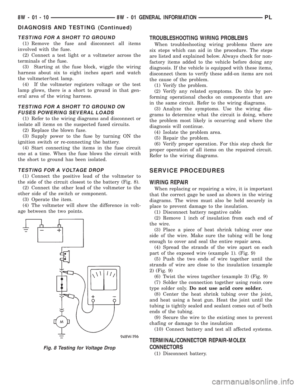
TESTING FOR A VOLTAGE DROP
(1) Connect the positive lead of the voltmeter to
the side of the circuit closest to the battery (Fig. 8).
(2) Connect the other lead of the voltmeter to the
other side of the switch or component.
(3) Operate the item.
(4) The voltmeter will show the difference in volt-
age between the two points.
TROUBLESHOOTING WIRING PROBLEMS
When troubleshooting wiring problems there are
six steps which can aid in the procedure. The steps
are listed and explained below. Always check for non-
factory items added to the vehicle before doing any
diagnosis. If the vehicle is equipped with these items,
disconnect them to verify these add-on items are not
the cause of the problem.
(1) Verify the problem.
(2) Verify any related symptoms. Do this by per-
forming operational checks on components that are
in the same circuit. Refer to the wiring diagrams.
(3) Analyze the symptoms. Use the wiring dia-
grams to determine what the circuit is doing, where
the problem most likely is occurring and where the
diagnosis will continue.
(4) Isolate the problem area.
(5) Repair the problem.
(6) Verify proper operation. For this step check for
proper operation of all items on the repaired circuit.
Refer to the wiring diagrams.
SERVICE PROCEDURES
WIRING REPAIR
When replacing or repairing a wire, it is important
that the correct gage be used as shown in the wiring
diagrams. The wires must also be held securely in
place to prevent damage to the insulation.
(1) Disconnect battery negative cable
(2) Remove 1 inch of insulation from each end of
the wire.
(3) Place a piece of heat shrink tubing over one
side of the wire. Make sure the tubing will be long
enough to cover and seal the entire repair area.
(4) Spread the strands of the wire apart on each
part of the exposed wire (example 1). (Fig. 9)
(5) Push the two ends of wire together until the
strands of wire are close to the insulation (example
2) (Fig. 9)
(6) Twist the wires together (example 3) (Fig. 9)
(7) Solder the connection together using rosin core
type solder only.Do not use acid core solder.
(8) Center the heat shrink tubing over the joint,
and heat using a heat gun. Heat the joint until the
tubing is tightly sealed and sealant comes out of both
ends of the tubing.
(9) Secure the wire to the existing ones to prevent
chafing or damage to the insulation
(10) Connect battery and test all affected systems.
TERMINAL/CONNECTOR REPAIR-MOLEX
CONNECTORS
(1) Disconnect battery.
Fig. 8 Testing for Voltage Drop
8W - 01 - 10 8W - 01 GENERAL INFORMATIONPL
DIAGNOSIS AND TESTING (Continued)
Page 410 of 1200

8W-02 COMPONENT INDEX
Component Page
A/C Compressor Clutch..................8W-42
A/C Compressor Clutch Relay.............8W-42
A/C Cycling Switch.....................8W-42
A/C Heater Blower Motor................8W-42
A/C Heater Control.....................8W-42
A/C Pressure Switches...................8W-42
ABS Warning Lamp Relay................8W-35
Airbag Control Module...................8W-43
Airbags..............................8W-43
Antenna..............................8W-47
Ash Receiver Lamp.....................8W-44
Automatic Shut Down Relay..............8W-30
Back-Up Lamp Switch...................8W-51
Back-Up Lamps........................8W-51
Battery..............................8W-20
Battery Temperature Sensor..............8W-30
Blower Motor Resistor Block..............8W-42
Brake Warning Lamp Switch...........8W-40, 50
Camshaft Position Sensor................8W-30
Center High Mounted Stop Lamp..........8W-51
Cigar Lighter Relay.....................8W-41
Cigar Lighter/Power Outlet...............8W-41
Circuit Breakers.......................8W-11
Clockspring.....................8W-30, 41, 61
Clutch Pedal Position Switch...........8W-10, 21
Combination Flasher....................8W-52
Controller Anti-Lock Brake...............8W-35
Crankshaft Position Sensor...............8W-30
Data Link Connector....................8W-30
Daytime Running Lamp Module...........8W-50
Diode No. 1........................8W-15, 42
Diode No. 2......................8W-10, 11, 44
Diode No. 3......................8W-11,44,70
Dome Lamp...........................8W-44
Door Ajar Switches.....................8W-44
Door Jamb Switches....................8W-44
Door Lock Motors......................8W-61
Door Lock Motors......................8W-61
Door Lock Switches.....................8W-61
Duty Cycle Evap/Purge Solenoid...........8W-30
EGR Transducer Solenoid................8W-30
Engine Coolant Temperature Sensor........8W-30
Engine Oil Pressure Switch...............8W-40
Engine Starter Motor....................8W-21
Engine Starter Motor Relay...............8W-21
Fog Lamp Relays....................8W-50, 51
Fog Lamp Switches..................8W-50, 51
Fog Lamps.........................8W-50, 51
Fuel Injectors..........................8W-30
Fuel Pump Module.....................8W-30
Fuel Pump Relay.......................8W-30
Fuse Block............................8W-11Component Page
Fuses (FB)............................8W-11
Fuses (PDC)...........................8W-10
Fusible Link........................8W-20, 21
Generator.............................8W-20
Glove Box Lamp And Switch..............8W-44
Grounds..............................8W-15
Halo Lamp............................8W-44
Headlamp Dimmer And Optical Horn Switch .8W-50
Headlamp Leveling Motors...............8W-50
Headlamp Leveling Switch...............8W-50
Headlamp Switch.......................8W-50
Headlamps............................8W-50
High Speed Warning Module..............8W-40
Horn Relay...........................8W-41
Horn Switches.........................8W-41
Horns................................8W-41
IAT/Map Sensor........................8W-30
Idle Air Control Motor...................8W-30
Ignition Coil Pack......................8W-30
Ignition Switch........................8W-10
Illumination Lamps.....................8W-40
Immobilizer...........................8W-61
Immobilizer Engine Sensor............8W-30, 61
Indicator Lamps........................8W-40
Instrument Cluster.....................8W-40
Intermittent Wipe/Wash Switch............8W-53
Key-In Switch.........................8W-40
Knock Sensor..........................8W-30
License Lamps.........................8W-51
Map/Reading Lamps....................8W-44
Noise Supressor.....................8W-10, 30
Oxygen Sensors........................8W-30
Park Brake Switch...................8W-40, 50
Park/Neutral Position Switch...........8W-30, 51
Park/Turn Signal Lamps..............8W-50, 52
Power Distribution Center................8W-10
Power Folding Mirror Relay...............8W-62
Power Mirror Fuse Holder................8W-62
Power Mirrors.........................8W-62
Power Steering Pressure Switch...........8W-30
Power Sunroof Motor....................8W-64
Power Window Motors...................8W-60
Power Window Switches.................8W-60
Powertrain Control Module...............8W-30
PRNDL Lamp.........................8W-44
Radiator Fan Motor.....................8W-42
Radio................................8W-47
Rear Window Defogger..................8W-48
Rear Window Defogger Switch.............8W-48
Remote Keyless Entry Module.............8W-61
Remote Keyless Entry Program
Module Connector....................8W-61
PL8W - 02 COMPONENT INDEX 8W - 02 - 1