Page 6 of 64

6
Principles
The suspension system
As ÓsupportingÓ components of the
suspension system, the suspension elements
form the connection between the wheel
suspension and the bodywork. This system is
complemented by the spring action of the
tyres and vehicle seats.
The suspension elements include steel
springs, gas/air and rubber/elastomers or
combinations of the above.
Steel spring suspensions have become well
established in passenger vehicles. Steel
springs are available in a wide variety of
designs, of which the coil spring has become
the most widespread.
Air suspension, which has been used for
many years in heavy goods vehicles, is
Þnding increasing application in passenger
vehicles due to its system-related
advantages.
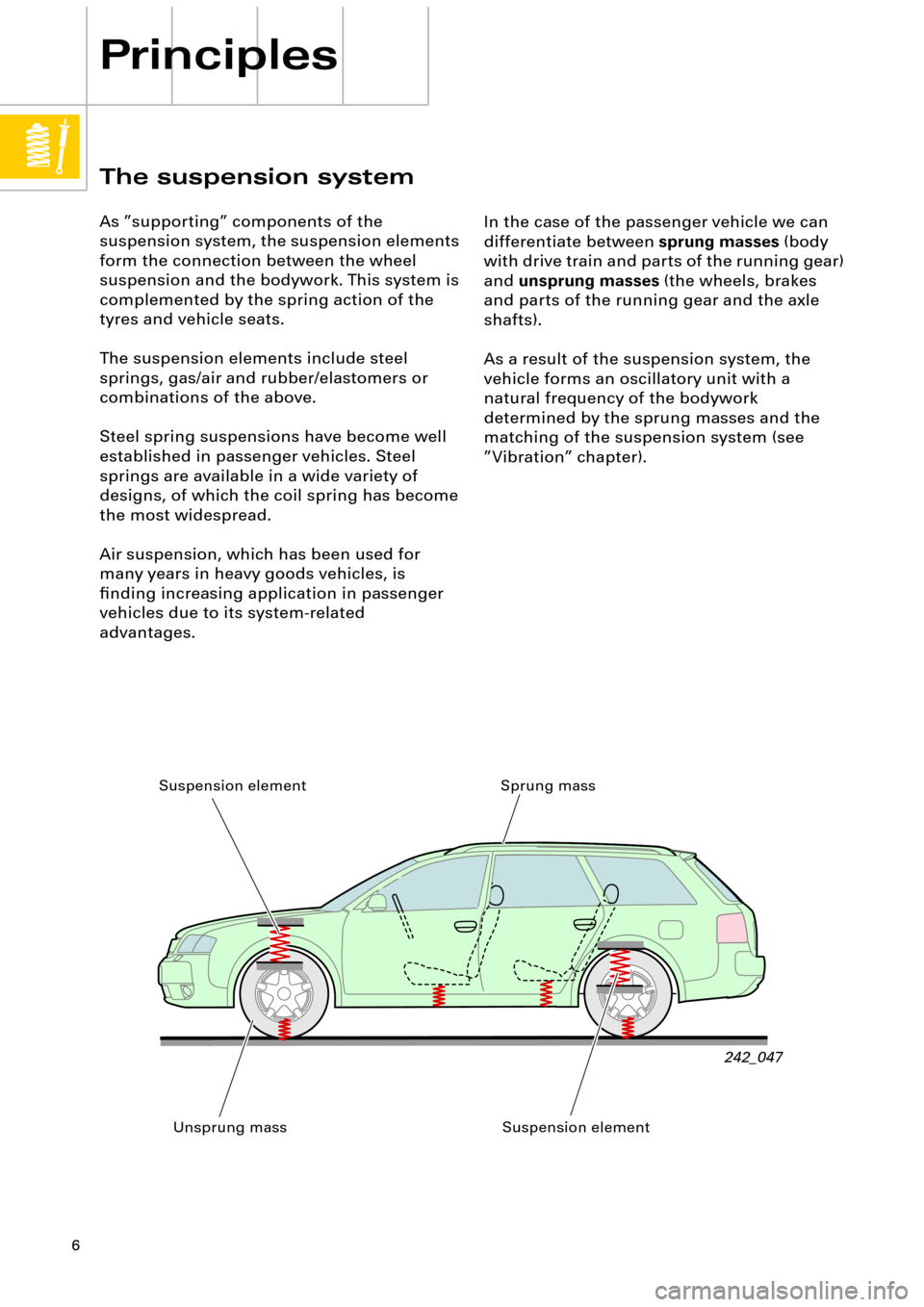
242_047
In the case of the passenger vehicle we can
differentiate between
sprung masses
(body
with drive train and parts of the running gear)
and
unsprung masses
(the wheels, brakes
and parts of the running gear and the axle
shafts).
As a result of the suspension system, the
vehicle forms an oscillatory unit with a
natural frequency of the bodywork
determined by the sprung masses and the
matching of the suspension system (see
ÓVibrationÓ chapter).
Sprung mass
Unsprung mass Suspension element
Suspension element
Page 7 of 64
7
The unsprung masses
The aim in principle is to minimise the volume
of unsprung masses and their inßuence on
the vibration characteristics (natural
frequency of the bodywork). Furthermore, a
low inertia of masses reduces the impact load
on the unsprung components and
signiÞcantly improves the response
characteristics of the suspension. These
effects result in a marked increase in driver
comfort.
Examples for the reduction of unsprung
masses:
¥ Aluminium hollow spoke wheel
¥ Running gear parts (swivel bearing, wheel
carrier, links etc.) made of aluminium
¥ Aluminium brake callipers
¥ Weight-optimised tyres
¥ Weight optimisation of running gear parts
(e.g. wheel hubs)
213_091
213_068
See also SSP 213, chapter ÒRunning
gearÓ.
213_041
Page 16 of 64
16
Principles of air suspension
Self-levelling air
suspension
Air suspension is a controllable form of
vehicle suspension.
With air suspension, it is simple to achieve
self-levelling and it is therefore generally
integrated into the system.
The basic advantages of self-levelling are:
¥ Static compression remains the same,
irrespective of vehicle loads (see overleaf).
The space requirement in the wheel
arches for free wheel movement kept to a
minimum, which has beneÞts for the
overall use of available space.
¥ The vehicle body can be suspended more
softly, which improves driving comfort.
¥ Full compression and rebound travel is
maintained, whatever the load.
242_074
¥ Ground clearance is maintained, whatever
the load.
¥ There are no track or camber changes
when vehicle is laden.
¥ The c
w value is maintained, as is the visual
appearance.
¥ Less wear to ball joints due to reduced
working angle.
¥ Greater loads are possible if required.
= constant
Page 17 of 64

17
In addition to the main advantages offered by
self-levelling, its realisation by means of air
suspension (Audi A6) offers another
signiÞcant advantage.
As the air pressure in the air springs is
adapted in accordance with the load, the
spring rate alters proportionally to the sprung
mass. The positive outcome is that the natural
frequency of the bodywork and thereby
driving comfort remain virtually constant,
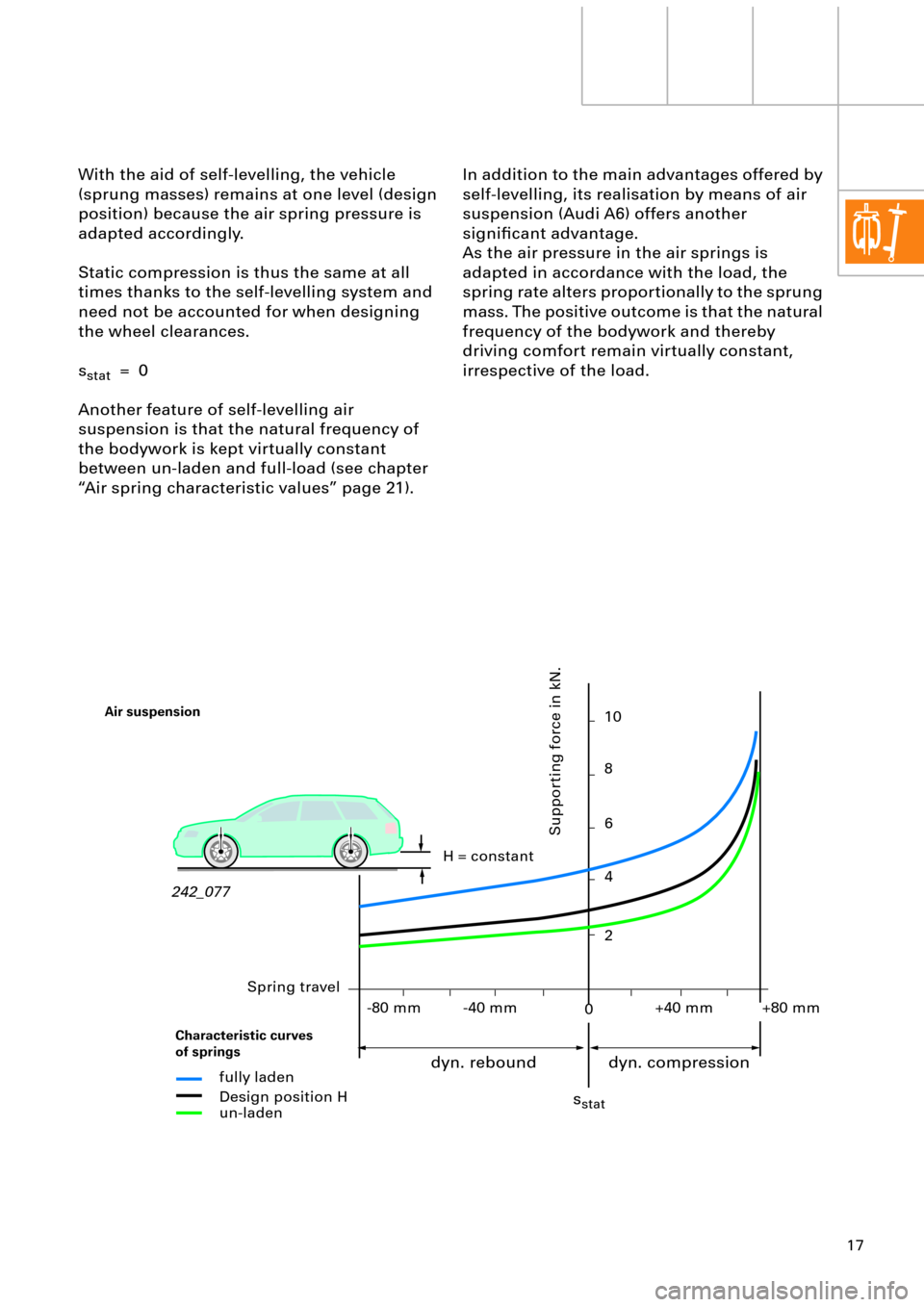
irrespective of the load. With the aid of self-levelling, the vehicle
(sprung masses) remains at one level (design
position) because the air spring pressure is
adapted accordingly.
Static compression is thus the same at all
times thanks to the self-levelling system and
need not be accounted for when designing
the wheel clearances.
s
stat = 0
Another feature of self-levelling air
suspension is that the natural frequency of
the bodywork is kept virtually constant
between un-laden and full-load (see chapter
ÒAir spring characteristic valuesÓ page 21).
242_077H = constant
fully laden
Design position H
un-laden
sstat
0
Supporting force in kN.
10
8
6
+80 mm+40 mm-40 mm -80 mm4
2
Air suspension
dyn. rebound dyn. compression
Spring travel
Characteristic curves
of springs
Page 20 of 64

20
Principles of air suspension
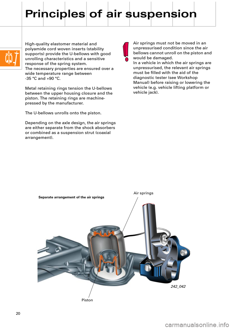
High-quality elastomer material and
polyamide cord woven inserts (stability
supports) provide the U-bellows with good
unrolling characteristics and a sensitive
response of the spring system.
The necessary properties are ensured over a
wide temperature range between
-35 ¡C and +90 ¡C.
Metal retaining rings tension the U-bellows
between the upper housing closure and the
piston. The retaining rings are machine-
pressed by the manufacturer.
The U-bellows unrolls onto the piston.
Depending on the axle design, the air springs
are either separate from the shock absorbers
or combined as a suspension strut (coaxial
arrangement).Air springs must not be moved in an
unpressurised condition since the air
bellows cannot unroll on the piston and
would be damaged.
In a vehicle in which the air springs are
unpressurised, the relevant air springs
must be Þlled with the aid of the
diagnostic tester (see Workshop
Manual) before raising or lowering the
vehicle (e.g. vehicle lifting platform or
vehicle jack).
242_042
Separate arrangement of the air springs
PistonAir springs
Page 21 of 64

21
-s +s± 0
Air spring parameters
Resilience/spring rate
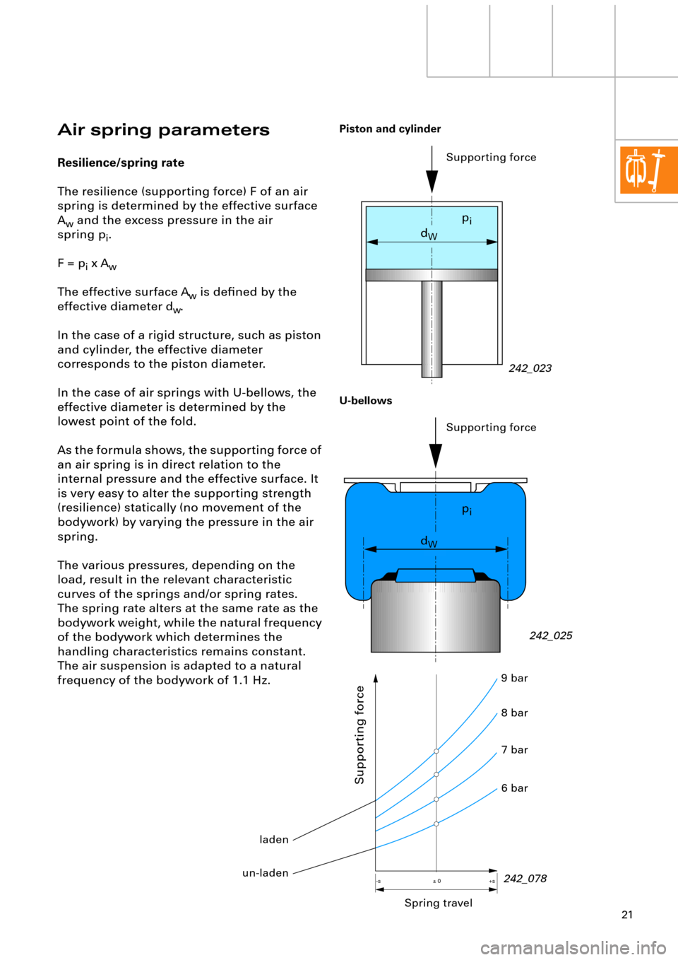
The resilience (supporting force) F of an air
spring is determined by the effective surface
A
w and the excess pressure in the air
spring p
i.
F = p
i x Aw
The effective surface Aw is deÞned by the
effective diameter d
w.
In the case of a rigid structure, such as piston
and cylinder, the effective diameter
corresponds to the piston diameter.
In the case of air springs with U-bellows, the
effective diameter is determined by the
lowest point of the fold.
As the formula shows, the supporting force of
an air spring is in direct relation to the
internal pressure and the effective surface. It
is very easy to alter the supporting strength
(resilience) statically (no movement of the
bodywork) by varying the pressure in the air
spring.
The various pressures, depending on the
load, result in the relevant characteristic
curves of the springs and/or spring rates.
The spring rate alters at the same rate as the
bodywork weight, while the natural frequency
of the bodywork which determines the
handling characteristics remains constant.
The air suspension is adapted to a natural
frequency of the bodywork of 1.1 Hz.
242_023
242_025 Supporting force
dW
Supporting force
dW
Piston and cylinder
U-bellows
Spring travel
Supporting force
242_078 6 bar 7 bar 8 bar 9 bar
pi
pi
laden
un-laden
Page 23 of 64
23
Example of the contour of a piston
(suspension strut in the Audi allroad quattro)
Vibration dampers are available in different
designs but their basic function and purpose
are the same.
Hydraulic/mechanical damping has found
widespread application in modern vehicle
design. The telescopic shock absorber is now
particularly favoured due to its small
dimensions, minimum friction, precise
damping and simple design.
Vibration damping
Without vibration damping, the vibration of
the masses during driving operation would
be increased to such an extent by repeated
road irregularities, that bodywork vibration
would build up increasingly and the wheels
would lose contact with the road surface.
The purpose of the vibration damping system
is to eliminate vibrations (energy) as quickly
as possible via the suspension.
For this purpose, hydraulic vibration dampers
(shock absorbers) are located parallel to the
springs.
242_079
U-bellows
Piston
Compressed
Page 29 of 64
29
0,13 0 0 200 400 600 800 1000
1200 1400 1600
0,26
0,390,520,650,78 0,91 1,04
Advantage of this matching:
Good response of the vehicle suspension
ensures greater driving comfort.
The disadvantage of this matching occurs in
the case of a quick succession of irregularities
in the road. If the time between the individual
impacts is no longer sufÞcient for rebound,
the suspension can ÒhardenÓ signiÞcantly in
extreme cases, impairing driver comfort and
driver safety. Damping matching
We can basically distinguish between
compression and rebound in the damping
process.
The damping force during compression is
generally smaller than during rebound.
Consequently, irregularities in the road are
transmitted to the vehicle bodywork with
diminished force. The spring absorbs the
energy which is quickly dissipated during
rebound by the more efÞcient action of the
shock absorber.
242_084
Piston speed in m/s
Damping force in N
Compression Rebound