1998 VOLVO V90 ignition
[x] Cancel search: ignitionPage 56 of 175

1998 Volvo S90
Chapter 3 - Body and interior (cont.)Luggage cover (wagon)
pg. 48
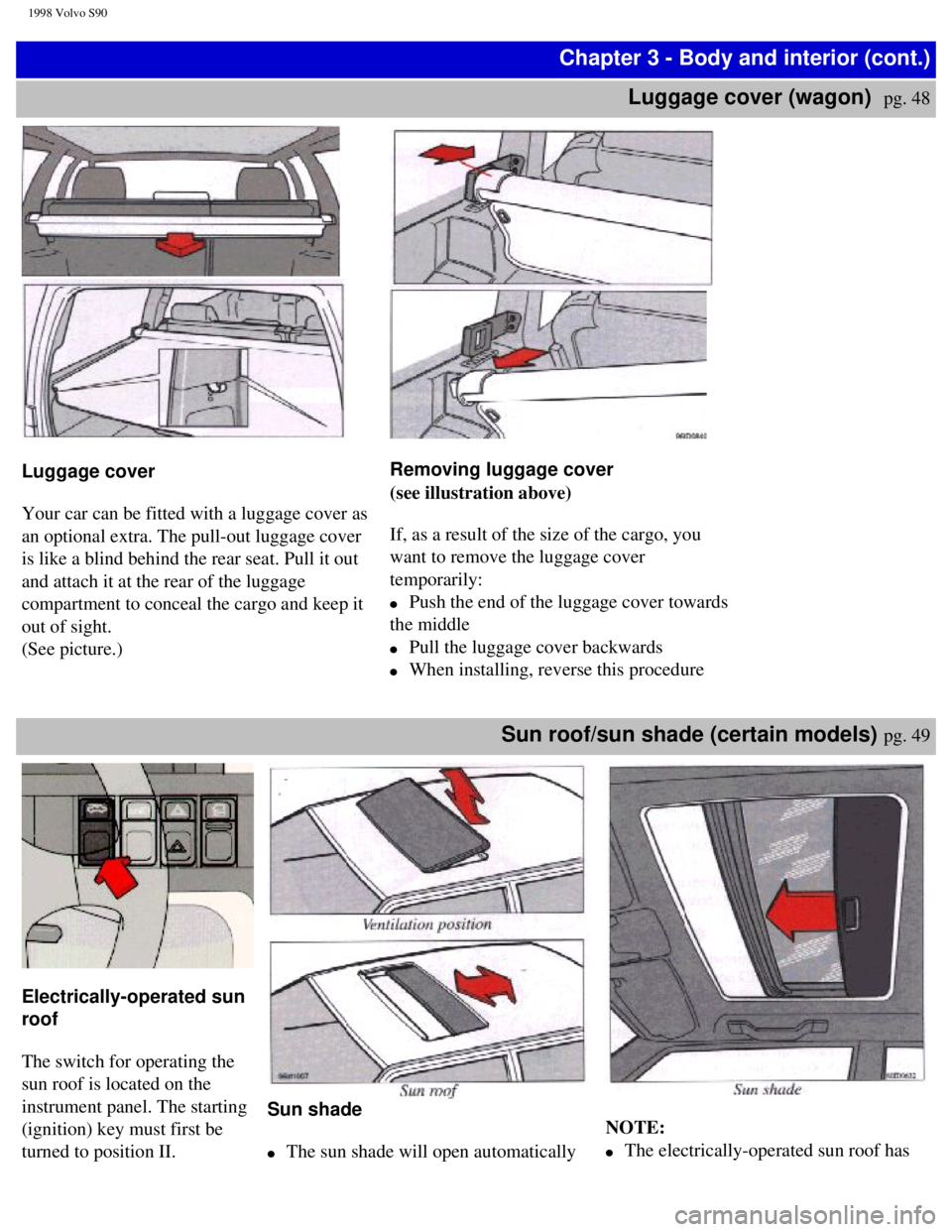
Luggage cover
Your car can be fitted with a luggage cover as
an optional extra. The pull-out luggage cover
is like a blind behind the rear seat. Pull it out
and attach it at the rear of the luggage
compartment to conceal the cargo and keep it
out of sight.
(See picture.)
Removing luggage cover
(see illustration above)
If, as a result of the size of the cargo, you
want to remove the luggage cover
temporarily:
l Push the end of the luggage cover towards
the middle
l Pull the luggage cover backwards
l When installing, reverse this procedure
Sun roof/sun shade (certain models) pg. 49
Electrically-operated sun
roof
The switch for operating the
sun roof is located on the
instrument panel. The starting
(ignition) key must first be
turned to position II.
Sun shade
l The sun shade will open automatically
NOTE:
l The electrically-operated sun roof has
file:///K|/ownersdocs/1998/1998_SV90/98S90_048.htm (1 of 4)12/30/2006 \
1:52:40 PM
Page 58 of 175

1998 Volvo S90
WARNING!
Always turn engine off and apply
parking brake when loading/
unloading the vehicle. Place
transmission selector in P (PARK)
position to help prevent
inadvertent movement of selector.
Alarm pg. 51
Alarm LED
Alarm
To lock: Press the lock/panic button
once to lock all doors and trunk/tailgate
and arm the security system. Lamps will
flash to acknowledge that the vehicle is
locked and the security system is armed.
To unlock: Press the unlock button once
to unlock the driver's door only and
disarm the security system.
Press the unlock button again (within 10
seconds) to unlock all doors and trunk/
tailgate.
Emergency function
To activate the " panic alarm
"function:
Press and hold lock/panic button for at
least 3 seconds. The car's lights will
flash and an alarm will sound for
approximately 30 seconds.
This function can be switched off at
any time by pressing either of the
buttons.
Programming a transmitter
New transmitters (max. 4) must be
programmed to function with your
alarm system. To do this:
l Make sure all doors, hood and
trunk/tailgate are closed.
l Turn the ignition on and off 5
times within 10 seconds. On the
fifth try, leave the ignition on.
l Press either button on the
transmitter. NOTE: The first transmitter must be
programmed within 15 seconds, the
others within 10 second intervals.
When the alarm system accepts the
codes from each transmitter, the
LED on the dash will glow steadily
for several seconds.
l Switch the ignition off and test the
transmitter(s).
Batteries
The remote transmitter is powered
by 2 three-volt batteries, type CR
1220. If three short signals are
audible from the transmitter each
time you lock/unlock the car, this
indicates that the batteries are weak.
Replacement: Remove the battery
cover on the back of the transmitter
with a coin. Replace the batteries.
Reinstall the cover, making sure it is
secured tightly to help protect the
transmitter.
NOTE: If only the driver's door is
unlocked, the lock will automatically
reengage (re-lock) and the alarm will
reset after 30 seconds unless the
door has been opened.
If all of the doors were unlocked (by
pushing button 2 twice within 10
seconds) and no door/trunk/tailgate
was opened within two minutes, all
locks will reengage and the alarm
will reset. This is to prevent the
vehicle from being left unlocked if
the unlock button is inadvertently
pressed.
The lock/unlock and alarm features
file:///K|/ownersdocs/1998/1998_SV90/98S90_048.htm (3 of 4)12/30/2006 \
1:52:40 PM
Page 64 of 175

1998 Volvo S90
(check when tires are cold). items and others are checked at
the standard Maintenance
Service intervals.
NOTE: Since using (D)rive
improves fuel economy, it
should be used as often as
possible.
Starting the engine pg. 57
Starting and stopping a
car equipped with
automatic transmission
1 Fasten the seat belt.
WARNING! Before
starting, check that the seat
is adjusted properly. Make
sure the brake pedal can be
depressed completely. Move
the seat closer if necessary.
Refer to section "Front
seats".
2 Apply the parking brake, if
not already set. The gear
selector is locked in the (P)ark
position (SHIFTLOCK).
3Without touching the
accelerator pedal ,turn the
ignition key to the starting
position. Allow the starter to
operate for 5-10 seconds.
Release the key as soon as the
engine starts. If the engine fails
to start, repeat step 3.
5 Select desired gear. The gear
engages after a slight delay,
especially noticeable when
selecting R.
CAUTION: Engine should
be idling; never accelerate
until after you feel the gear
engage! Too rapid
acceleration immediately
after selecting a gear will
cause harsh engagement and
premature transmission
wear.
NOTE:Your car is equipped
with a KEYLOCK system.
When the engine is switched
off, the gear selector must be in
the (P)ark position before the
key can be removed from the
ignition switch.
Engine warm-up - initial
driving procedure
Engines in vehicles driven short
distances are subject to
abnormally rapid wear because
the engine never reaches normal
operating temperature. It is
therefore beneficial to reach
normal operating temperature as
soon as possible. This is best
achieved by driving with a light
foot on the accelerator pedal for
a few minutes after starting,
rather than prolonged idling.
B6304 S Engine
This engine features hydraulic
valve lifters which means that
valve clearance is adjusted
automatically. It is possible that
the valve lifters will produce a
ticking sound for the first few
seconds after the engine is
started, while the oil pressure is
increasing.
If the car has not been used for a
long period of time, this ticking
sound may last for up to 15
minutes. This is entirely normal.
file:///K|/ownersdocs/1998/1998_SV90/98S90_053.htm (5 of 6)12/30/2006 \
1:52:41 PM
Page 70 of 175

1998 Volvo S90
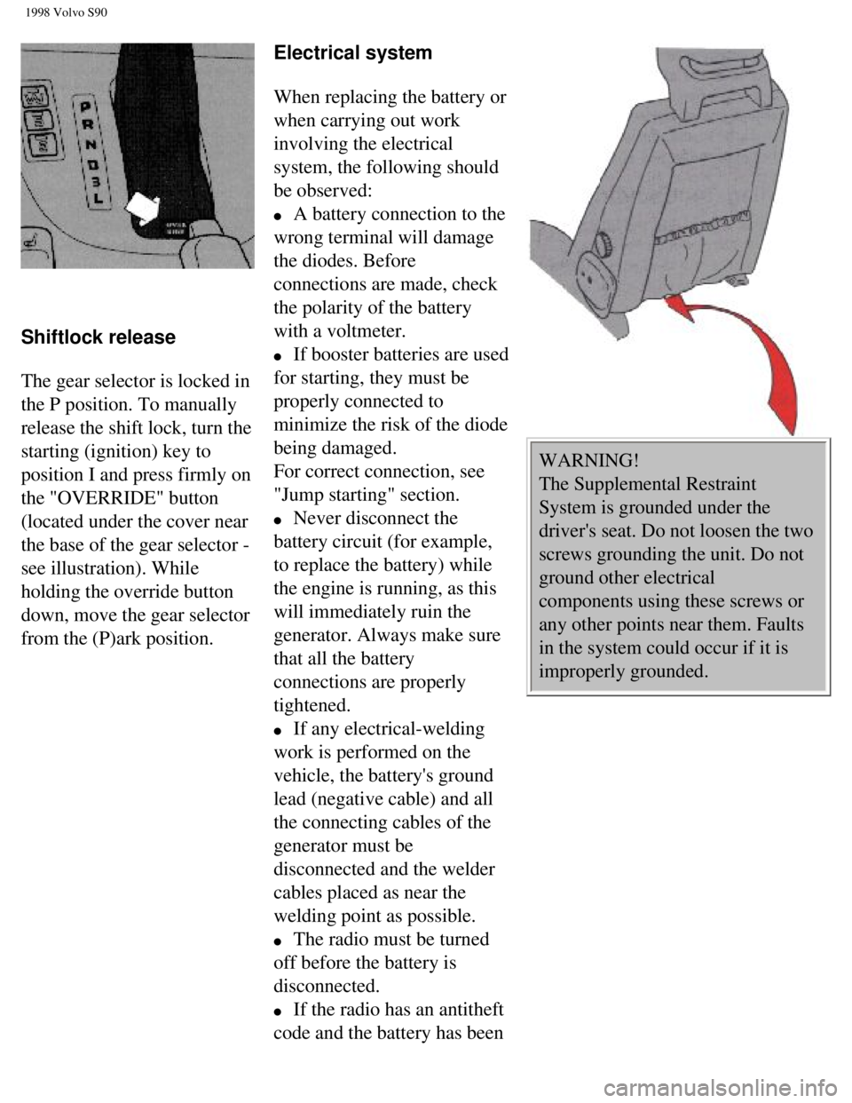
Shiftlock release
The gear selector is locked in
the P position. To manually
release the shift lock, turn the
starting (ignition) key to
position I and press firmly on
the "OVERRIDE" button
(located under the cover near
the base of the gear selector -
see illustration). While
holding the override button
down, move the gear selector
from the (P)ark position. Electrical system
When replacing the battery or
when carrying out work
involving the electrical
system, the following should
be observed:
l A battery connection to the
wrong terminal will damage
the diodes. Before
connections are made, check
the polarity of the battery
with a voltmeter.
l If booster batteries are used
for starting, they must be
properly connected to
minimize the risk of the diode
being damaged.
For correct connection, see
"Jump starting" section.
l Never disconnect the
battery circuit (for example,
to replace the battery) while
the engine is running, as this
will immediately ruin the
generator. Always make sure
that all the battery
connections are properly
tightened.
l If any electrical-welding
work is performed on the
vehicle, the battery's ground
lead (negative cable) and all
the connecting cables of the
generator must be
disconnected and the welder
cables placed as near the
welding point as possible.
l The radio must be turned
off before the battery is
disconnected.
l If the radio has an antitheft
code and the battery has been
WARNING!
The Supplemental Restraint
System is grounded under the
driver's seat. Do not loosen the two
screws grounding the unit. Do not
ground other electrical
components using these screws or
any other points near them. Faults
in the system could occur if it is
improperly grounded.
file:///K|/ownersdocs/1998/1998_SV90/98S90_058.htm (5 of 7)12/30/2006 \
1:52:42 PM
Page 75 of 175

1998 Volvo S90
cable.
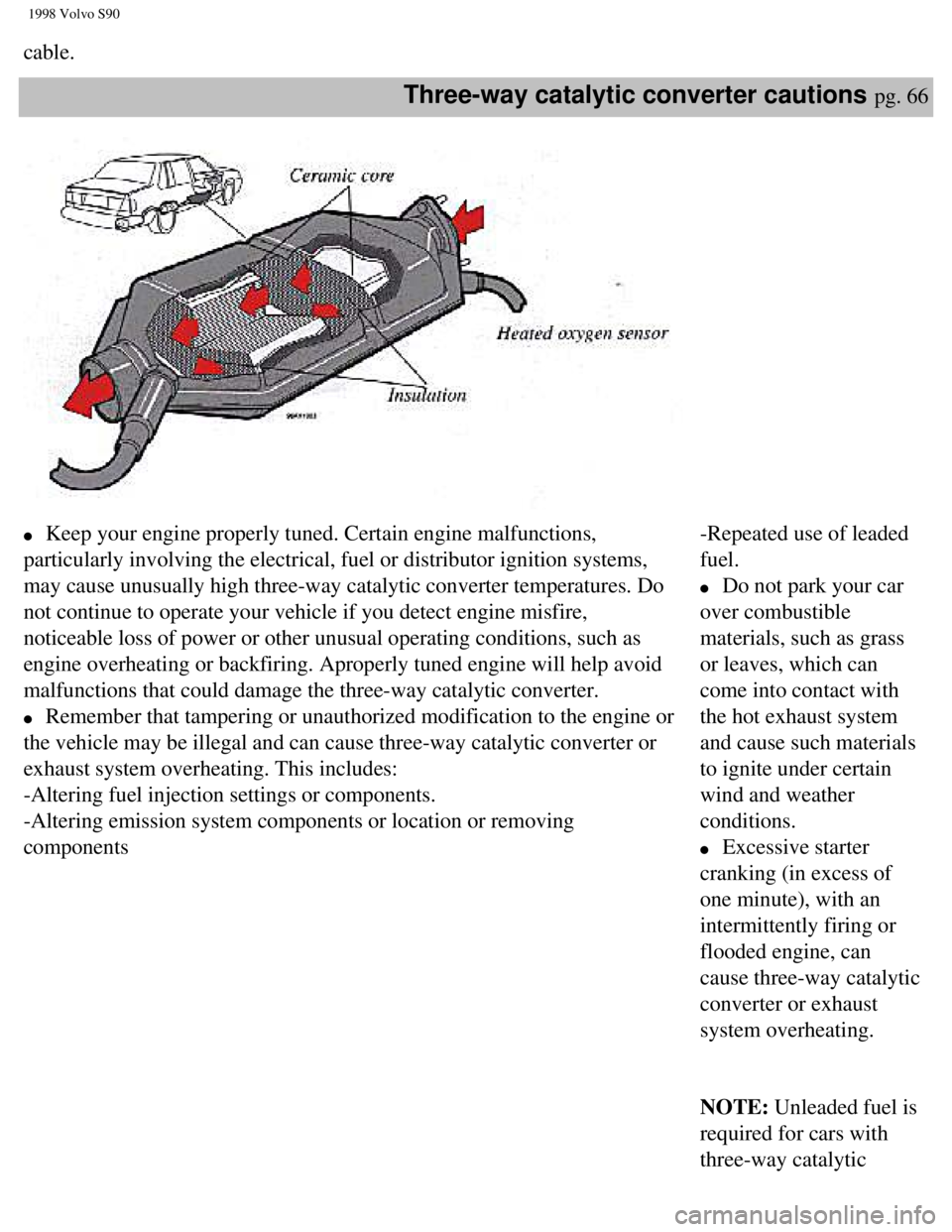
Three-way catalytic converter cautions pg. 66
l Keep your engine properly tuned. Certain engine malfunctions,
particularly involving the electrical, fuel or distributor ignition syst\
ems,
may cause unusually high three-way catalytic converter temperatures. Do \
not continue to operate your vehicle if you detect engine misfire,
noticeable loss of power or other unusual operating conditions, such as \
engine overheating or backfiring. Aproperly tuned engine will help avoid\
malfunctions that could damage the three-way catalytic converter.
l Remember that tampering or unauthorized modification to the engine or
the vehicle may be illegal and can cause three-way catalytic converter o\
r
exhaust system overheating. This includes:
-Altering fuel injection settings or components.
-Altering emission system components or location or removing
components -Repeated use of leaded
fuel.
l Do not park your car
over combustible
materials, such as grass
or leaves, which can
come into contact with
the hot exhaust system
and cause such materials
to ignite under certain
wind and weather
conditions.
l Excessive starter
cranking (in excess of
one minute), with an
intermittently firing or
flooded engine, can
cause three-way catalytic
converter or exhaust
system overheating.
NOTE: Unleaded fuel is
required for cars with
three-way catalytic
file:///K|/ownersdocs/1998/1998_SV90/98S90_063.htm (3 of 4)12/30/2006 \
1:52:43 PM
Page 91 of 175

1998 Volvo S90
Chapter 6 - (cont.)
Replacing bulbs
pg. 81
Replacing bulbs
The method for replacement of bulbs in
the various lighting units is shown on the
following pages. Make sure when
installing bulbs, that the guide pin on the
socket fits into its corresponding recess.
When installing Halogen bulbs, do not
touch the glass with your fingers because
grease, oil or any other impurities can be
carbonized onto the bulb and damage the
reflector.
Use bulbs of correct type and voltage.
Failure to do so could cause the bulb
failure warning light to activate.
NOTE: Turn the ignition and light
switch off before replacing any bulbs.
Headlights (high/low beams)
1. Press the protruding tabs on the plastic
cover and pull out towards the fender.
2. Turn the bulb and connector 1/4 turn
counterclockwise and remove.
3. Remove the connector from the bulb.
4. Press a new bulb into the connector
without touching the bulb itself.
5. Reinsert the bulb into the headlight
housing and turn 1/4 turn clockwise until
the unit seats properly.
6. Reinstall the plastic cover.
Bulb Power US Bulb No.
High beam 70W HB3/9005
Low beam 60W HB4/9006
Headlight adjustment
The height of the headlight beams can be
adjusted according to vehicle load. The
headlights should be re-aimed if heavy
loads are carried in the trunk/cargo area or
rear seat, or when towing a trailer.
To adjust the headlights:
Park the car on a level surface and open
the hood.
The headlights are equipped with a level
which can be seen by looking through the
clear "window" on the top of the headlight
lens.
Turn the height adjustment knob (A) until
the bubble in the level aligns with within
the marking lines on the level.
Lateral headlight adjustment (B) should
only be carried out by an authorized
Volvo retailer. This setting should be
preset to "0".
Replacing bulbs pg. 82
file:///K|/ownersdocs/1998/1998_SV90/98S90_081.htm (1 of 6)12/30/2006 \
1:52:45 PM
Page 93 of 175

1998 Volvo S90
Replacing tail light bulbs (sedan
models)
All tail lamp bulbs are replaced from inside of
trunk. To avoid confusion, replace the bulbs one
at a time.
l Switch off the lights and ignition.
l Outboard lights: Unscrew screw A and turn
down the cover panel.
l Trunk lid: Lift the catch and fold down the
cover panel.
l Remove the bulb holder.
l Remove bulb by pressing and turning 1/4
turn counterclockwise.
l Insert a new bulb and fit the bulb holder in
the tail light cluster. One of the plugs on the
bulb holder is slightly wider than the other two.
l Turn the bulb holder clockwise to secure it.
Check that the bulb lights and refit the cover. Bulbs / Power CP(W) / Socket / US Bulb No
1,4 Tail light / 4(5) / BA 15s / 67
2 Rear turn signal / (21) / BAU 15s / –
3 Brake light / 32 / (21) / BA 15s / 1156
5 Back-up light / 32 (21) / BA 15s / 1156
6 Rear foglamp* 32 (21) / BA 15s / 1156
*Left (driver's) side only
Replacing bulbs, Sedans pg. 84
Light / Power CP(W) / Socket / US Bulb
No.
1 Fog light* / 32(21) / BA 15s / 1156
2 Back-up lights / 32(21) / BA 15 s / 1156
3 Turn signals / (21) / BAU 15 s / -
4 Brake light and tail light / 32/3(21/5) /
BAZ 15 d / 1157
*One light only, on driver's side
21 W 21 W 21/5 W
BA 15 s BAU 15 s BAY 15 d
Replacing tail light bulbs
(wagon models)
l Turn off the lights.
l Remove the cover with a screw driver.
l Rotate the bulb holder about 1/4" (0.6
cm) counterclockwise and remove the
holder from the tail light cluster.
l Gently press the bulb into the holder,
then rotate the bulb counterclockwise in
order to release it.
l Install a new bulb in the holder and
replace the bulb holder in the tail light
cluster. One of the guide lugs on the bulb holder
is slightly wider than the other two and,
thus, this lug fits into the widest recess
only.
l Turn the bulb holder clockwise
l Check that the bulb lights
l Re-install cluster cover
Two types of bulbs are in use
The guide lugs on the twin-pole bulb are
at different heights, and it is only possible
to fit these bulbs in one way. Try at first to
turn the bulb gently. Do not use force. If
this does not work, take out the bulb and
turn it half a turn and try again.
Replacing bulbs (cont.) pg. 85
file:///K|/ownersdocs/1998/1998_SV90/98S90_081.htm (3 of 6)12/30/2006 \
1:52:45 PM
Page 95 of 175

1998 Volvo S90
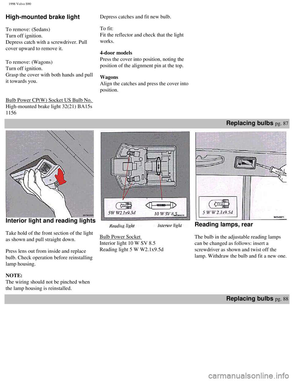
High-mounted brake light
To remove: (Sedans)
Turn off ignition.
Depress catch with a screwdriver. Pull
cover upward to remove it.
To remove: (Wagons)
Turn off ignition.
Grasp the cover with both hands and pull
it towards you.
Bulb Power CP(W) Socket US Bulb No.
High-mounted brake light 32(21) BA15s
1156 Depress catches and fit new bulb.
To fit:
Fit the reflector and check that the light
works.
4-door models
Press the cover into position, noting the
position of the alignment pin at the top.
Wagons
Align the catches and press the cover into
position.
Replacing bulbs pg. 87
Interior light and reading lights
Take hold of the front section of the light
as shown and pull straight down.
Press lens out from inside and replace
bulb. Check operation before reinstalling
lamp housing.
NOTE:
The wiring should not be pinched when
the lamp housing is reinstalled.
Bulb Power Socket
Interior light 10 W SV 8.5
Reading light 5 W W2.1x9.5d
Reading lamps, rear
The bulb in the adjustable reading lamps
can be changed as follows: insert a
screwdriver as shown and twist off the
lamp. Withdraw the bulb and fit a new one.
Replacing bulbs pg. 88
file:///K|/ownersdocs/1998/1998_SV90/98S90_081.htm (5 of 6)12/30/2006 \
1:52:45 PM