Page 41 of 3115
N20013
R-Shape
RotorSnap Ring
Compressor
AC1743
AC1744
AC0950
SST
N20012
R-Shape
Snap Ring
CompressorStator AC-64
- AIR CONDITIONINGCOMPRESSOR AND MAGNETIC CLUTCH
2789 Author�: Date�:
2004 LAND CRUISER (RM1071U)
NOTICE:
At the time of reassembly, the snap ring should be installed
so that beveled side facing up.
(b) Using a plastic hammer, tap the rotor off the shaft.
NOTICE:
Be careful not to damage the pulley when tapping on the ro-
tor.
3. REMOVE STATOR
(a) Disconnect the stator lead wire from the compressor
housing.
(b) Using SST, remove the snap ring.
SST 95994-10020
NOTICE:
At the time of reassembly, the snap ring should be installed
so that its beveled side facing up.
Page 128 of 3115

D12656
(a)(b)
(a)
(a)
(b)(b)
D12657
D12658
D12659
(c)(b)
D12660
- AUTOMATIC TRANSMISSIONAUTOMATIC TRANSMISSION UNIT
AT-31
1885 Author�: Date�:
2004 LAND CRUISER (RM1071U)
10. SEPARATE WIRE HARNESS
(a) Disconnect 3 connectors.
(b) Remove the 3 clamps from the transmission unit and sep-
arate the transmission wire.
11. REMOVE TORQUE CONVERTER CLUTCH MOUNT-
ING BOLT
(a) Remove the bolt and the hole plug.
Torque: 18 N´m (185 kgf´cm, 13 ft´lbf)
(b) Turn the crankshaft to gain access to each bolt.
(c) Hold the crankshaft pulley nut with a wrench, and remove
the 6 bolts.
Torque: 48 N´m (490 kgf´cm, 35 ft´lbf)
HINT:
At the time of installation, first install the green colored bolt. And
then install the other 5 bolts.
12. DISCONNECT OIL COOLER PIPES
(a) Loosen the 2 union nuts.
(b) Remove the bolt and the clamp.
Torque: 12 N´m (122 kgf´cm, 9 ft´lbf)
(c) Remove the 2 union nuts and disconnect the 2 oil cooler
pipes.
Torque: 34 N´m (347 kgf´cm, 25 ft´lbf)
13. SEPARATE GROUND CABLE
Remove the bolt and separate the ground cable.
Torque: 20 N´m (204 kgf´cm, 15 ft´lbf)
14. REMOVE CROSSMEMBER AND TRANSTER CASE
PROTECTOR
(a) Support the transmission with a jack.
Page 599 of 3115

Z00030
B00807
B00808
B
A
AC2024
CORRECT WRONG
- CHARGINGCHARGING SYSTEM
CH-3
1838 Author�: Date�:
2004 LAND CRUISER (RM1071U)
5. INSPECT DRIVE BELT
HINT:
A belt tensioner is used, so checking the belt tension is not nec-
essary.
(a) Visually check the drive belt for excessive wear, frayed
cords etc.
If necessary, replace the drive belt.
HINT:
�Cracks on the rib side of a drive belt are considered ac-
ceptable. If the drive belt has chunks missing from the
ribs, it should be replaced.
�The drive belt tension can be released by turning the belt
tensioner counterclockwise. The pulley bolt for the belt
tensioner has a left-hand thread.
(b) Check the belt tensioner operation.
�Check that the belt tensioner moves downward
when the drive belt is pressed down at the points in-
dicated in the illustration with approx. 98 N (10 kgf,
22.0 lbf) of force.
�Check the alignment of the belt tensioner pulley to
make sure the drive belt has not slipped off the
pulley.
If necessary, replace the belt tensioner.
�Check that the arrow mark on the belt tensioner falls
within area A of the scale.
If it is outside area A, replace the drive belt.
HINT:
�When a new belt is installed, it should lie within area B. If
not, the drive belt is not correct.
�After installing a belt, check that it fits properly in the
ribbed grooves.
�Check by hand to confirm that the belt has not slipped out
of the groove on the bottom of the pulley.
6. REMOVE ENGINE UNDER COVER NO.1
7. VISUALLY CHECK GENERATOR WIRING AND LIS-
TEN FOR ABNORMAL NOISES
(a) Check that the wiring is in good condition.
(b) Check that there is no abnormal noise from the generator
while the engine is running.
Page 602 of 3115
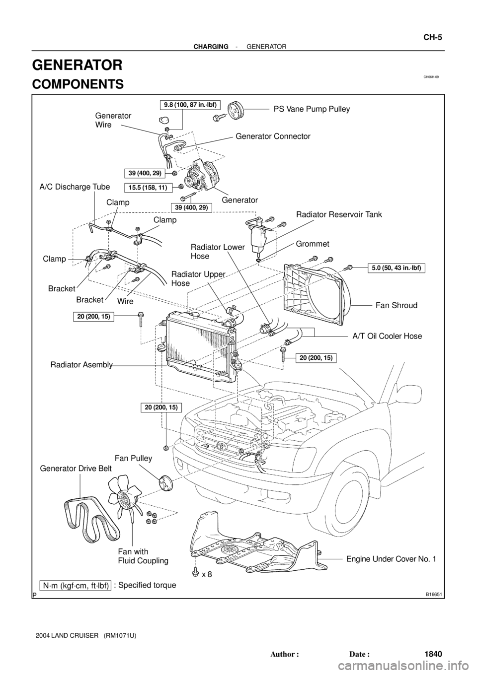
CH06H-09
B16651N´m (kgf´cm, ft´lbf): Specified torque
Radiator Reservoir Tank
Fan Shroud
A/T Oil Cooler Hose Bracket
Fan Pulley
Generator Drive Belt
x 8Engine Under Cover No. 1
BracketWire
A/C Discharge Tube
Clamp
Clamp
Radiator Lower
Hose
Radiator Upper
HoseGrommet
Fan with
Fluid Coupling Radiator Asembly
Clamp
Generator Generator
Wire
Generator ConnectorPS Vane Pump Pulley
9.8 (100, 87 in.´lbf)
39 (400, 29)
15.5 (158, 11)
39 (400, 29)
5.0 (50, 43 in.´lbf)
20 (200, 15)
20 (200, 15)
20 (200, 15)
- CHARGINGGENERATOR
CH-5
1840 Author�: Date�:
2004 LAND CRUISER (RM1071U)
GENERATOR
COMPONENTS
Page 603 of 3115
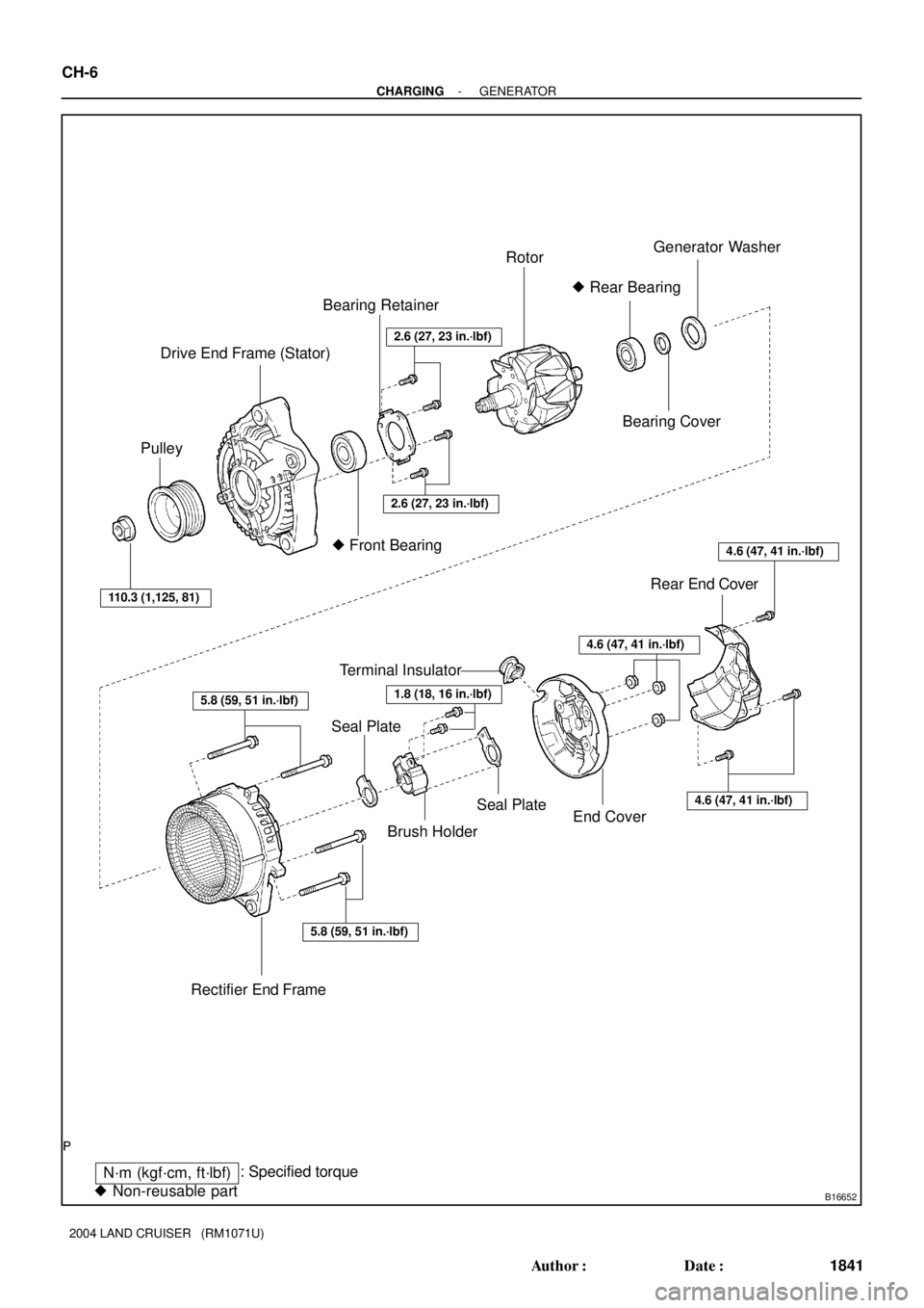
B16652
Pulley
� Front Bearing
Seal Plate Bearing Retainer
� Rear Bearing
Drive End Frame (Stator)Rotor
Generator Washer
Bearing Cover
Rectifier End Frame
Terminal Insulator
Brush Holder
� Non-reusable partEnd Cover
N´m (kgf´cm, ft´lbf): Specified torque
Seal Plate
110.3 (1,125, 81)
2.6 (27, 23 in.´lbf)
2.6 (27, 23 in.´lbf)
5.8 (59, 51 in.´lbf)
5.8 (59, 51 in.´lbf)
1.8 (18, 16 in.´lbf)
4.6 (47, 41 in.´lbf)
Rear End Cover
4.6 (47, 41 in.´lbf)
4.6 (47, 41 in.´lbf)
CH-6
- CHARGINGGENERATOR
1841 Author�: Date�:
2004 LAND CRUISER (RM1071U)
Page 604 of 3115
CH06J-03
B16654
B16655
B16362
B16369SST (B)
SST (A)
Turn
B16371
SST (C)
SST (B)
Insert
CH-8
- CHARGINGGENERATOR
1843 Author�: Date�:
2004 LAND CRUISER (RM1071U)
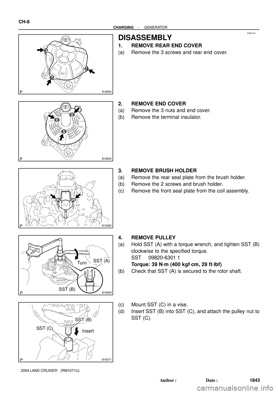
DISASSEMBLY
1. REMOVE REAR END COVER
(a) Remove the 3 screws and rear end cover.
2. REMOVE END COVER
(a) Remove the 3 nuts and end cover.
(b) Remove the terminal insulator.
3. REMOVE BRUSH HOLDER
(a) Remove the rear seal plate from the brush holder.
(b) Remove the 2 screws and brush holder.
(c) Remove the front seal plate from the coil assembly.
4. REMOVE PULLEY
(a) Hold SST (A) with a torque wrench, and tighten SST (B)
clockwise to the specified torque.
SST 09820-6301 1
Torque: 39 N´m (400 kgf´cm, 29 ft´lbf)
(b) Check that SST (A) is secured to the rotor shaft.
(c) Mount SST (C) in a vise.
(d) Insert SST (B) into SST (C), and attach the pulley nut to
SST (C).
Page 605 of 3115
B16372
SST (C)
SST (A)
Turn
B16370
Turn
SST (A)
SST (B)
B16656
B16366
SST
- CHARGINGGENERATOR
CH-9
1844 Author�: Date�:
2004 LAND CRUISER (RM1071U)
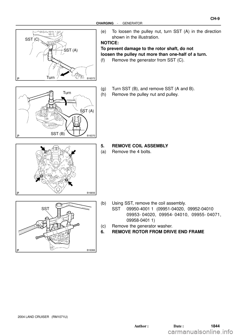
(e) To loosen the pulley nut, turn SST (A) in the direction
shown in the illustration.
NOTICE:
To prevent damage to the rotor shaft, do not
loosen the pulley nut more than one-half of a turn.
(f) Remove the generator from SST (C).
(g) Turn SST (B), and remove SST (A and B).
(h) Remove the pulley nut and pulley.
5. REMOVE COIL ASSEMBLY
(a) Remove the 4 bolts.
(b) Using SST, remove the coil assembly.
SST 09950-4001 1 (09951-04020, 09952-04010
09953- 04020, 09954- 04010, 09955- 04071,
09958-0401 1)
(c) Remove the generator washer.
6. REMOVE ROTOR FROM DRIVE END FRAME
Page 607 of 3115
CH06N-05
B16653
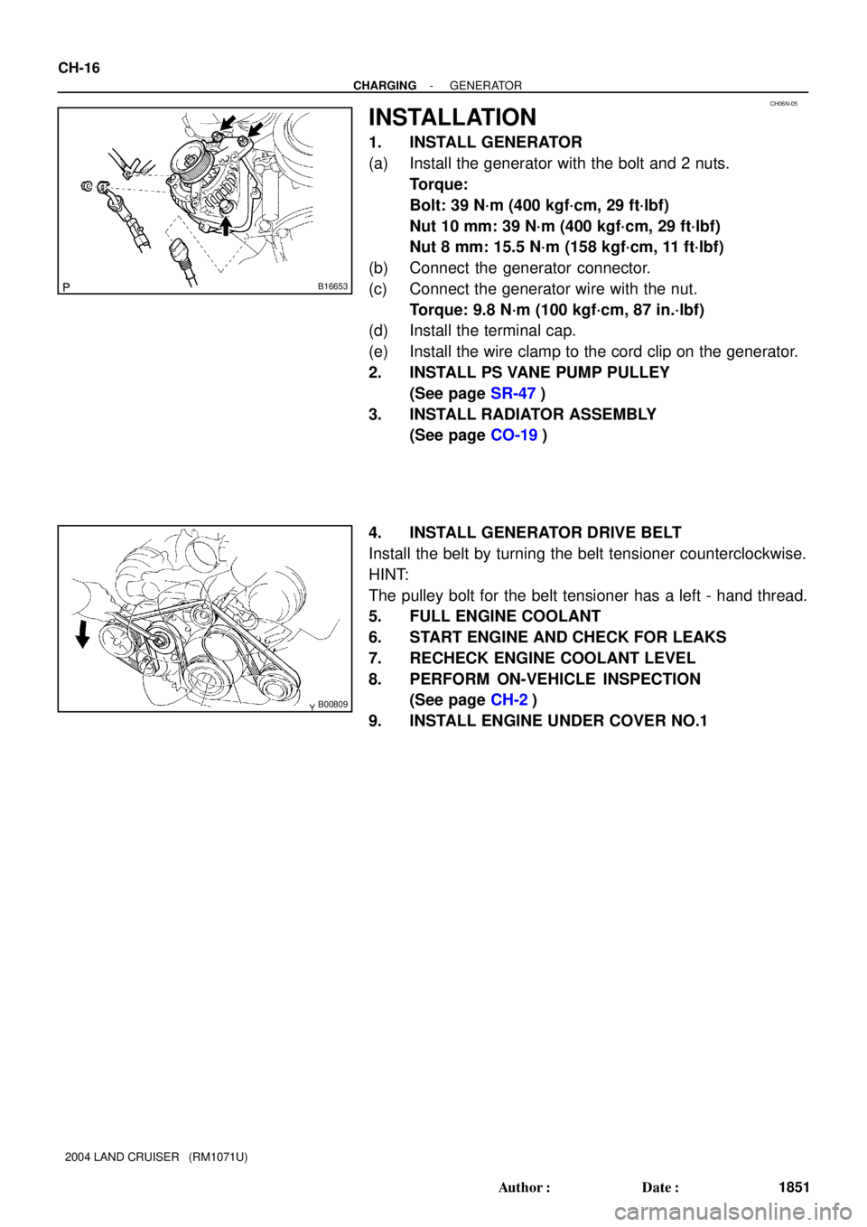
B00809
CH-16
- CHARGINGGENERATOR
1851 Author�: Date�:
2004 LAND CRUISER (RM1071U)
INSTALLATION
1. INSTALL GENERATOR
(a) Install the generator with the bolt and 2 nuts.
Torque:
Bolt: 39 N´m (400 kgf´cm, 29 ft´lbf)
Nut 10 mm: 39 N´m (400 kgf´cm, 29 ft´lbf)
Nut 8 mm: 15.5 N´m (158 kgf´cm, 11 ft´lbf)
(b) Connect the generator connector.
(c) Connect the generator wire with the nut.
Torque: 9.8 N´m (100 kgf´cm, 87 in.´lbf)
(d) Install the terminal cap.
(e) Install the wire clamp to the cord clip on the generator.
2. INSTALL PS VANE PUMP PULLEY
(See page SR-47)
3. INSTALL RADIATOR ASSEMBLY
(See page CO-19)
4. INSTALL GENERATOR DRIVE BELT
Install the belt by turning the belt tensioner counterclockwise.
HINT:
The pulley bolt for the belt tensioner has a left - hand thread.
5. FULL ENGINE COOLANT
6. START ENGINE AND CHECK FOR LEAKS
7. RECHECK ENGINE COOLANT LEVEL
8. PERFORM ON-VEHICLE INSPECTION
(See page CH-2)
9. INSTALL ENGINE UNDER COVER NO.1