Page 599 of 3115

Z00030
B00807
B00808
B
A
AC2024
CORRECT WRONG
- CHARGINGCHARGING SYSTEM
CH-3
1838 Author�: Date�:
2004 LAND CRUISER (RM1071U)
5. INSPECT DRIVE BELT
HINT:
A belt tensioner is used, so checking the belt tension is not nec-
essary.
(a) Visually check the drive belt for excessive wear, frayed
cords etc.
If necessary, replace the drive belt.
HINT:
�Cracks on the rib side of a drive belt are considered ac-
ceptable. If the drive belt has chunks missing from the
ribs, it should be replaced.
�The drive belt tension can be released by turning the belt
tensioner counterclockwise. The pulley bolt for the belt
tensioner has a left-hand thread.
(b) Check the belt tensioner operation.
�Check that the belt tensioner moves downward
when the drive belt is pressed down at the points in-
dicated in the illustration with approx. 98 N (10 kgf,
22.0 lbf) of force.
�Check the alignment of the belt tensioner pulley to
make sure the drive belt has not slipped off the
pulley.
If necessary, replace the belt tensioner.
�Check that the arrow mark on the belt tensioner falls
within area A of the scale.
If it is outside area A, replace the drive belt.
HINT:
�When a new belt is installed, it should lie within area B. If
not, the drive belt is not correct.
�After installing a belt, check that it fits properly in the
ribbed grooves.
�Check by hand to confirm that the belt has not slipped out
of the groove on the bottom of the pulley.
6. REMOVE ENGINE UNDER COVER NO.1
7. VISUALLY CHECK GENERATOR WIRING AND LIS-
TEN FOR ABNORMAL NOISES
(a) Check that the wiring is in good condition.
(b) Check that there is no abnormal noise from the generator
while the engine is running.
Page 607 of 3115
CH06N-05
B16653
B00809
CH-16
- CHARGINGGENERATOR
1851 Author�: Date�:
2004 LAND CRUISER (RM1071U)
INSTALLATION
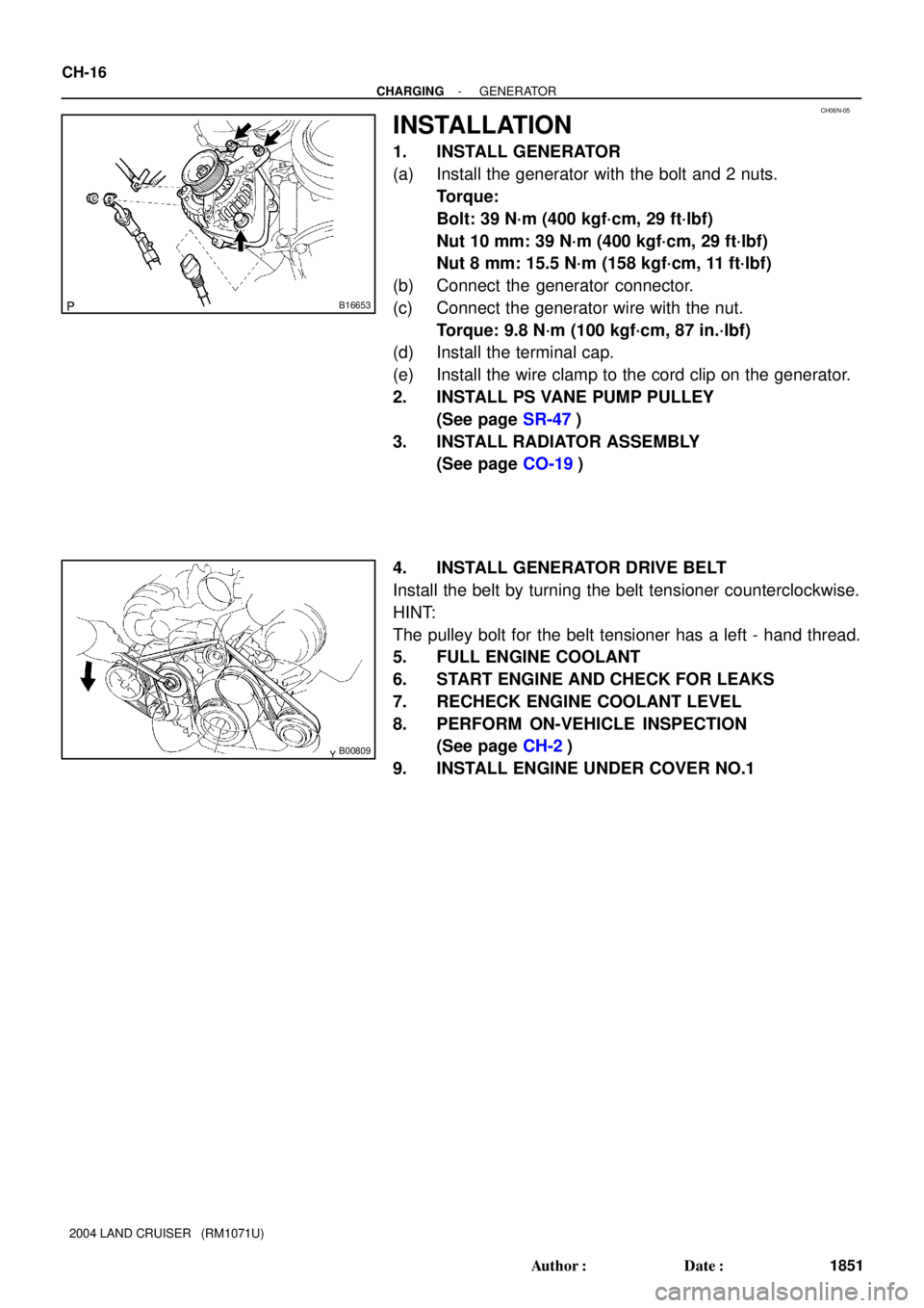
1. INSTALL GENERATOR
(a) Install the generator with the bolt and 2 nuts.
Torque:
Bolt: 39 N´m (400 kgf´cm, 29 ft´lbf)
Nut 10 mm: 39 N´m (400 kgf´cm, 29 ft´lbf)
Nut 8 mm: 15.5 N´m (158 kgf´cm, 11 ft´lbf)
(b) Connect the generator connector.
(c) Connect the generator wire with the nut.
Torque: 9.8 N´m (100 kgf´cm, 87 in.´lbf)
(d) Install the terminal cap.
(e) Install the wire clamp to the cord clip on the generator.
2. INSTALL PS VANE PUMP PULLEY
(See page SR-47)
3. INSTALL RADIATOR ASSEMBLY
(See page CO-19)
4. INSTALL GENERATOR DRIVE BELT
Install the belt by turning the belt tensioner counterclockwise.
HINT:
The pulley bolt for the belt tensioner has a left - hand thread.
5. FULL ENGINE COOLANT
6. START ENGINE AND CHECK FOR LEAKS
7. RECHECK ENGINE COOLANT LEVEL
8. PERFORM ON-VEHICLE INSPECTION
(See page CH-2)
9. INSTALL ENGINE UNDER COVER NO.1
Page 760 of 3115
CO0IS-01
B04067Air HoleWa t e r
Hole
- COOLINGWATER PUMP
CO-7
1768 Author�: Date�:
2004 LAND CRUISER (RM1071U)
INSPECTION
1. INSPECT WATER PUMP
(a) Visually check the air hole and water hole for coolant leak-
age.
If leakage is found, replace the water pump and timing belt.
(b) Turn the pulley, and check that the water pump bearing
moves smoothly and quietly.
If necessary, replace the water pump.
2. INSPECT TIMING BELT COMPONENTS
(See page EM-20)
Page 1246 of 3115

FI7059
FI7060A00069
G2 and NE Signal Waveforms
20 msec./Division (Idling)
10 msec./Division (Idling)5 V
/Division
G2
NE
5 V
/Division
G2
NE
- DIAGNOSTICSENGINE
DI-197
390 Author�: Date�:
2004 LAND CRUISER (RM1071U)
DTC P0340 Camshaft Position Sensor ºAº Circuit
(Bank 1 or Single Sensor)
DTC P0341 Camshaft Position Sensor ºAº Circuit
Range/Performance (Single Sensor)
CIRCUIT DESCRIPTION
The camshaft position sensor (G signal) consists of a magnet iron core and pickup coil.
The G signal plate has 1 tooth on its outer circumference and is installed on the LH camshaft timing pulley.
When the camshafts rotate, protrusion on the signal plate and air gap on the pickup coil change, causing
fluctuations in the magnetic field and generating a voltage in the pickup coil.
The NE signal plate has 34 teeth and is mounted on the crankshaft. The NE signal sensor generates 34
signals at every engine revolution. The ECM detects the crankshaft angle and the engine revolution based
on the NE signals, and the cylinder and the angle of the G2 based on the combination of the G and NE sig-
nals.
DTC No.DTC Detection ConditionTrouble Area
P0340
No camshaft position sensor signal to ECM during cranking
(2 trip detection logic)
P0340No camshaft position sensor signal to ECM with engine
speed 600 rpm or more (1 trip detection logic)�Open or short in camshaft position sensor circuit
�Camshaftposition sensor
P0341
While crankshaft rotates twice, camshaft position sensor
signal will be input to ECM 12 times or more (1 trip detec-
tion logic)
�Hint:
Under normal condition, the camshaft position signal is
input into the ECM 3 times per 2 engine revolutions�Camshaft position sensor
�LH camshaft timing pulley
�Jumping teeth of timing belt
�ECM
Reference: Inspection using the oscilloscope.
The correct waveform is as shown.
Tester ConnectionSpecified Condition
G2+ (E7-27) - G2- (E7-32)Ct fi hNE+ (E7-25) - NE- (E7-24)Correct waveform is as shown
DIC2E-01
Page 1250 of 3115
- DIAGNOSTICSENGINE
DI-201
394 Author�: Date�:
2004 LAND CRUISER (RM1071U)
4 Inspect teeth of LH camshaft timing belt pulley.
PREPARATION:
Remove the LH camshaft timing belt pulley (See page EM-35).
CHECK:
Check the LH camshaft timing belt pulley.
NG Replace LH camshaft timing pulley.
OK
Replace ECM (See page SF-60).
Page 1889 of 3115

EM0KX-06
EM3336
NO !
P20079
P20633
EM-20
- ENGINE MECHANICALTIMING BELT
1593 Author�: Date�:
2004 LAND CRUISER (RM1071U)
INSPECTION
1. INSPECT TIMING BELT
NOTICE:
�Do not bend, twist or turn the timing belt inside out.
�Do not allow the timing belt to contact with oil, water
or steam.
�Do not utilize timing belt tension when installing or re-
moving the mount bolt of the camshaft timing pulley.
If there any defects as shown in the illustrations, check these
points:
(a) Premature parting
�Check for proper installation.
�Check the timing cover gasket for damage and
proper installation.
(b) If the belt teeth are cracked or damaged, check if either
camshaft is locked.
(c) If there is noticeable wear or cracks on the belt face,
check if there are nicks on the side of the idler pulley lock
and the water pump.
(d) Even if there is wear or damage on only one side of the
belt, check the belt guide and the alignment of each
pulley.
(e) If there is noticeable wear on the belt teeth, check timing
cover for damage and for foreign materials on the pulley
teeth.
If necessary, replace the timing belt.
2. INSPECT IDLER PULLEYS
(a) Visually check the seal portion of the idler pulley for oil
leakage.
If leakage is found, replace the idler pulley.
(b) Check that the idler pulley turns smoothly.
If necessary, replace the idler pulley.
3. INSPECT TIMING BELT TENSIONER
(a) Visually check the seal portion of the tensioner for oil leak-
age.
HINT:
If there is only the faintest trace of oil on the seal on the push
rod side, the tensioner is all right.
If leakage is found, replace the tensioner.
Page 1902 of 3115

EM0KS-08
A04324
A04325
EM-4
- ENGINE MECHANICALVALVE CLEARANCE
1577 Author�: Date�:
2004 LAND CRUISER (RM1071U)
VALVE CLEARANCE
INSPECTION
HINT:
Inspect and adjust the valve clearance when the engine is cold.
1. DRAIN ENGINE COOLANT
2. REMOVE BATTERY CLAMP COVER
3. REMOVE V-BANK COVER
4. REMOVE AIR CLEANER AND INTAKE AIR CONNEC-
TOR ASSEMBLY
5. REMOVE NO.3 TIMING BELT COVERS
(See page EM-15)
6. REMOVE IGNITION COILS (See page IG-6)
7. REMOVE RH CYLINDER HEAD COVER
Remove the 9 bolts, the 9 seal washers and the cylinder head
cover.
8. REMOVE LH CYLINDER HEAD COVER
(a) Remove the oil dipstick for the transmission.
(b) Disconnect the PCV hose.
(c) Disconnect the engine wire clamp from the wire bracket
on the cylinder head cover.
(d) Remove the 9 bolts, the 9 seal washers and the cylinder
head cover.
9. SET NO.1 CYLINDER TO TDC/COMPRESSION
(a) Turn the crankshaft pulley, and align its groove with timing
mark º0º of the No.1 timing belt cover.
(b) Check that the timing marks of the camshaft timing pul-
leys and that of the timing belt rear plates are aligned.
If not, turn the crankshaft 1 revolution (360°) and align the mark
as above.