Page 1816 of 3115

A05095
1
248
6
3
5
9
7
10
A05094
Front
Painted
Mark90° 90°
A04854A04883A04884A05177
Front Mark
(1 Cavity)
Front
LH
Piston
RH
PistonFront
Front Mark
(2 Cavities)
EM-1 10
- ENGINE MECHANICALCYLINDER BLOCK
1683 Author�: Date�:
2004 LAND CRUISER (RM1071U)
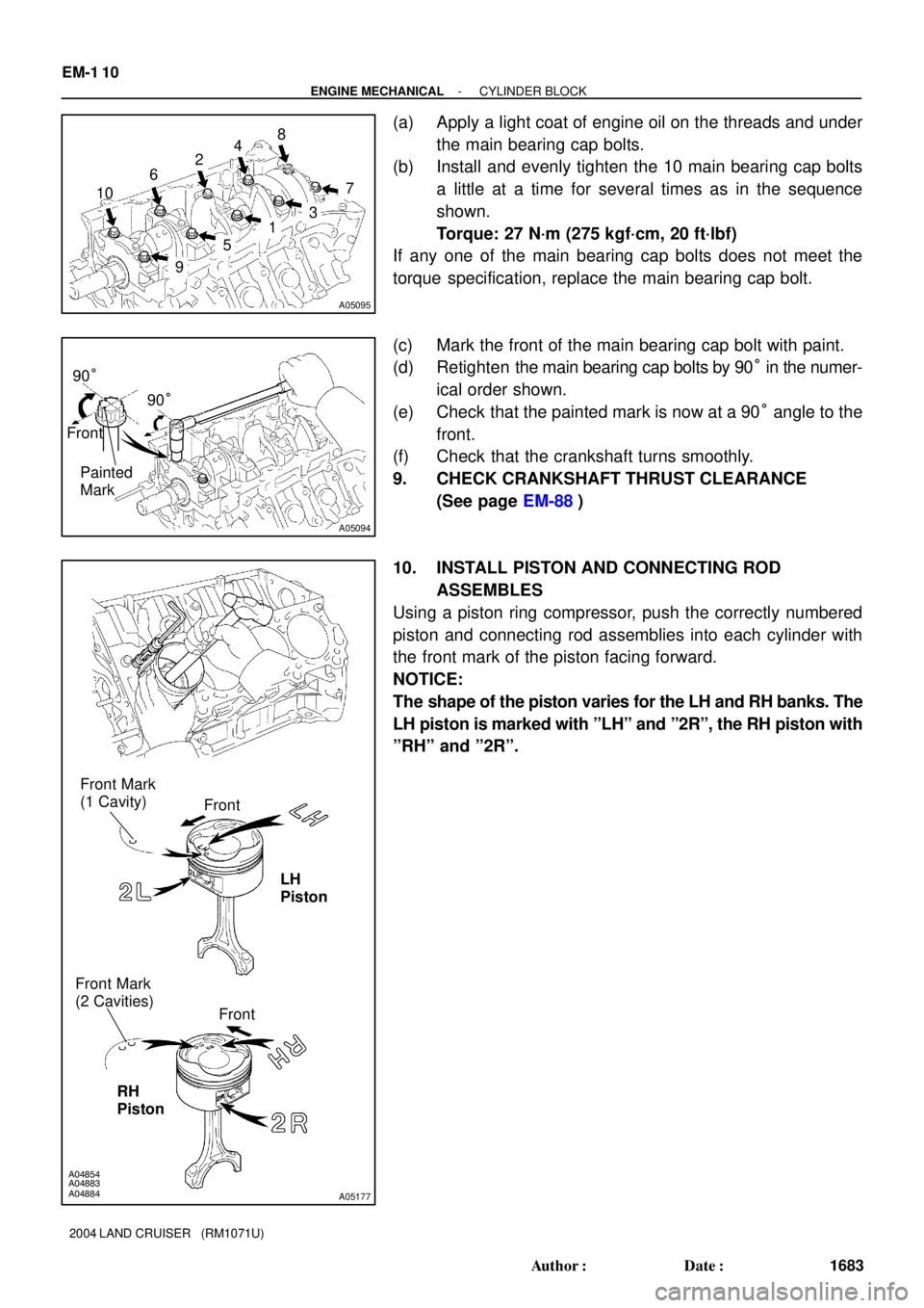
(a) Apply a light coat of engine oil on the threads and under
the main bearing cap bolts.
(b) Install and evenly tighten the 10 main bearing cap bolts
a little at a time for several times as in the sequence
shown.
Torque: 27 N´m (275 kgf´cm, 20 ft´lbf)
If any one of the main bearing cap bolts does not meet the
torque specification, replace the main bearing cap bolt.
(c) Mark the front of the main bearing cap bolt with paint.
(d) Retighten the main bearing cap bolts by 90° in the numer-
ical order shown.
(e) Check that the painted mark is now at a 90° angle to the
front.
(f) Check that the crankshaft turns smoothly.
9. CHECK CRANKSHAFT THRUST CLEARANCE
(See page EM-88)
10. INSTALL PISTON AND CONNECTING ROD
ASSEMBLES
Using a piston ring compressor, push the correctly numbered
piston and connecting rod assemblies into each cylinder with
the front mark of the piston facing forward.
NOTICE:
The shape of the piston varies for the LH and RH banks. The
LH piston is marked with ºLHº and º2Rº, the RH piston with
ºRHº and º2Rº.
Page 1817 of 3115

A05106
A05107A05108A05174
Front
Outside Mark
(Protrusion)
RH Bank LH Bank
Front
Outside Mark
(Protrusion)
A05101
A05099
Painted
Mark Front90°
90°
- ENGINE MECHANICALCYLINDER BLOCK
EM-1 11
1684 Author�: Date�:
2004 LAND CRUISER (RM1071U)
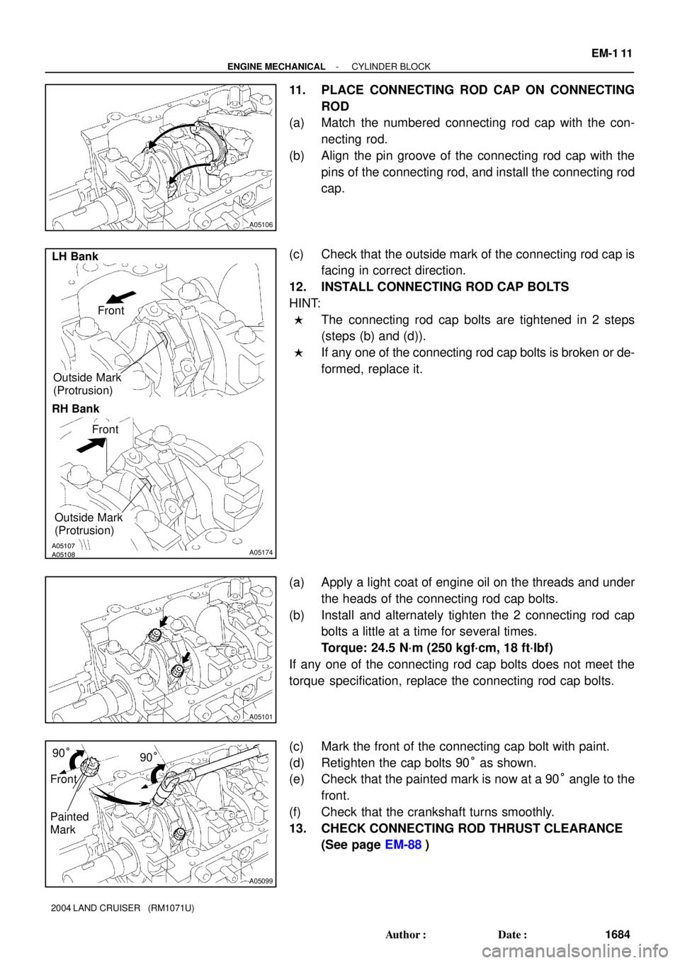
11. PLACE CONNECTING ROD CAP ON CONNECTING
ROD
(a) Match the numbered connecting rod cap with the con-
necting rod.
(b) Align the pin groove of the connecting rod cap with the
pins of the connecting rod, and install the connecting rod
cap.
(c) Check that the outside mark of the connecting rod cap is
facing in correct direction.
12. INSTALL CONNECTING ROD CAP BOLTS
HINT:
�The connecting rod cap bolts are tightened in 2 steps
(steps (b) and (d)).
�If any one of the connecting rod cap bolts is broken or de-
formed, replace it.
(a) Apply a light coat of engine oil on the threads and under
the heads of the connecting rod cap bolts.
(b) Install and alternately tighten the 2 connecting rod cap
bolts a little at a time for several times.
Torque: 24.5 N´m (250 kgf´cm, 18 ft´lbf)
If any one of the connecting rod cap bolts does not meet the
torque specification, replace the connecting rod cap bolts.
(c) Mark the front of the connecting cap bolt with paint.
(d) Retighten the cap bolts 90° as shown.
(e) Check that the painted mark is now at a 90° angle to the
front.
(f) Check that the crankshaft turns smoothly.
13. CHECK CONNECTING ROD THRUST CLEARANCE
(See page EM-88)
Page 1836 of 3115

Z00055
Width
Z03988
45°30°
1.0 - 1.4 mm
Z03989
60°45°
1.0 - 1.4 mm
EM6331
EM0988
Deviation
- ENGINE MECHANICALCYLINDER HEAD
EM-49
1622 Author�: Date�:
2004 LAND CRUISER (RM1071U)
(b) Check the valve seating position.
Apply a light coat of prussian blue (or white lead) to the
valve face. Lightly press the valve against the seat. Do not
rotate valve.
(c) Check the valve face and seat for the following:
�If blue appears 360° around the face, the valve is
concentric. If not, replace the valve.
�If blue appears 360° around the valve seat, the
guide and face are concentric. If not, resurface the
seat.
�Check that the seat contact is in the middle of the
valve face with the following width:
1.0 - 1.4 mm (0.039 - 0.055 in.)
If not, correct the valve seats as follows:
�If the seating is too high on the valve face, use 30°
and 45° cutters to correct the seat.
�If the seating is too low on the valve face, use 60°
and 45° cutters to correct the seat.
(d) Hand-lap the valve and valve seat with an abrasive com-
pound.
(e) After hand-lapping, clean the valve and valve seat.
12. INSPECT VALVE SPRINGS
(a) Using a steel square, measure the deviation of the valve
spring.
Maximum deviation:
2.0 mm (0.079 in.)
If the deviation is greater than the maximum, replace the valve
spring.
Page 1849 of 3115

A05507
Push
A04470
E D E
C
A
E D
E C B
A04470
10
1
2
56789
111213
141516
17 18
19
2022
3
4
21
A02856
Service
Bolt
EM-66
- ENGINE MECHANICALCYLINDER HEAD
1639 Author�: Date�:
2004 LAND CRUISER (RM1071U)
(8) Push in the camshaft oil seal.
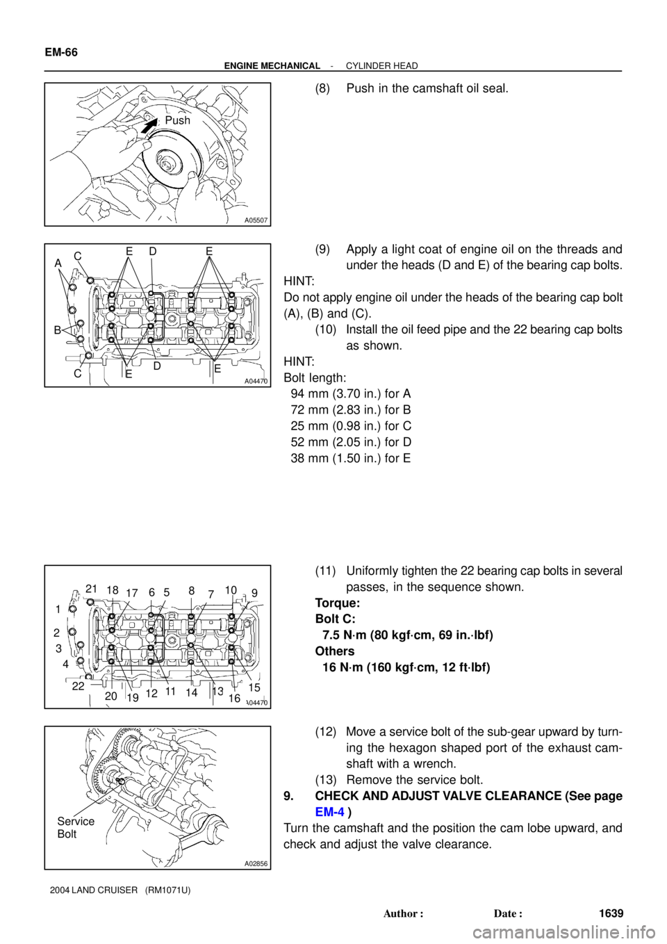
(9) Apply a light coat of engine oil on the threads and
under the heads (D and E) of the bearing cap bolts.
HINT:
Do not apply engine oil under the heads of the bearing cap bolt
(A), (B) and (C).
(10) Install the oil feed pipe and the 22 bearing cap bolts
as shown.
HINT:
Bolt length:
94 mm (3.70 in.) for A
72 mm (2.83 in.) for B
25 mm (0.98 in.) for C
52 mm (2.05 in.) for D
38 mm (1.50 in.) for E
(11) Uniformly tighten the 22 bearing cap bolts in several
passes, in the sequence shown.
Torque:
Bolt C:
7.5 N´m (80 kgf´cm, 69 in.´lbf)
Others
16 N´m (160 kgf´cm, 12 ft´lbf)
(12) Move a service bolt of the sub-gear upward by turn-
ing the hexagon shaped port of the exhaust cam-
shaft with a wrench.
(13) Remove the service bolt.
9. CHECK AND ADJUST VALVE CLEARANCE (See page
EM-4)
Turn the camshaft and the position the cam lobe upward, and
check and adjust the valve clearance.
Page 1855 of 3115
A05712
SST
A07306
EM-58
- ENGINE MECHANICALCYLINDER HEAD
1631 Author�: Date�:
2004 LAND CRUISER (RM1071U)
(c) Using SST, compress the valve spring and place the 2
keepers around the valve stem.
SST 09202-70020
(d) Using a plastic-faced hammer and the valve stem tip
taped up with vinyl tape, lightly tap the valve stem tip to
assure proper fit.
NOTICE:
Be careful not to damage the valve stem tip.
3. INSTALL SHIMS AND VALVE LIFTERS
(a) Install the shim and the valve lifter.
(b) Check that the valve lifter rotates smoothly by hand.
Page 1884 of 3115

EM0KT-10
A07061
TOYOTA Hand-Held Tester
DLC3
A05511
A05512
SSTTC
E1
A04459
- ENGINE MECHANICALIGNITION TIMING
EM-9
1582 Author�: Date�:
2004 LAND CRUISER (RM1071U)
IGNITION TIMING
INSPECTION
1. REMOVE BATTERY CLAMP COVER
2. REMOVE INTAKE AIR CONNECTOR
3. REMOVE V-BANK COVER
4. WARM UP ENGINE
Allow the engine to warm up to the normal operating tempera-
ture.
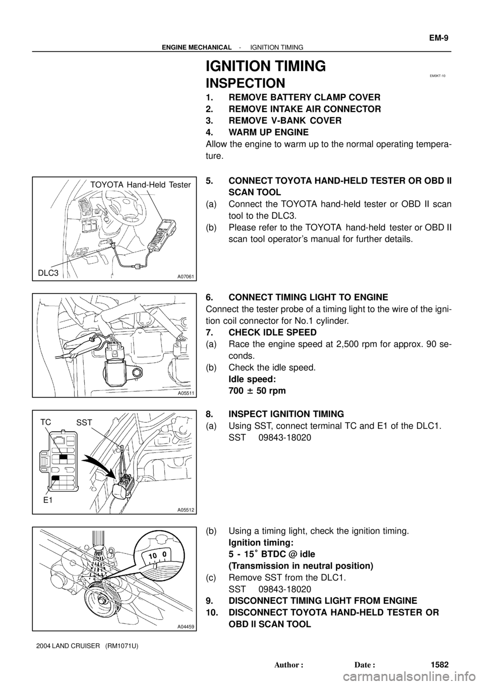
5. CONNECT TOYOTA HAND-HELD TESTER OR OBD II
SCAN TOOL
(a) Connect the TOYOTA hand-held tester or OBD II scan
tool to the DLC3.
(b) Please refer to the TOYOTA hand-held tester or OBD II
scan tool operator's manual for further details.
6. CONNECT TIMING LIGHT TO ENGINE
Connect the tester probe of a timing light to the wire of the igni-
tion coil connector for No.1 cylinder.
7. CHECK IDLE SPEED
(a) Race the engine speed at 2,500 rpm for approx. 90 se-
conds.
(b) Check the idle speed.
Idle speed:
700 ± 50 rpm
8. INSPECT IGNITION TIMING
(a) Using SST, connect terminal TC and E1 of the DLC1.
SST 09843-18020
(b) Using a timing light, check the ignition timing.
Ignition timing:
5 - 15° BTDC @ idle
(Transmission in neutral position)
(c) Remove SST from the DLC1.
SST 09843-18020
9. DISCONNECT TIMING LIGHT FROM ENGINE
10. DISCONNECT TOYOTA HAND-HELD TESTER OR
OBD II SCAN TOOL
Page 2410 of 3115

F02201N09214F05476
E1
DLC1
CG Ts
DLC3
Ts
B04696
Center Differential Lock
Indicator Light
Center Differential
Switch
Transfer Select
Lever
IN-18
- INTRODUCTIONFOR ALL OF VEHICLES
18 Author�: Date�:
2004 LAND CRUISER (RM1071U)
2. FOR VEHICLE EQUIPPED WITH VEHICLE SKID CON-
TROL (VSC) SYSTEM
(a) Precaution when using drum tester:
When using a drum tester, make sure that the ignition
switch is OFF, start the engine with the diagnosis connec-
tor short-circuited between Ts and E
1 (CG) and take a
measurement.
NOTICE:
�Check that VSC warning light is blinking.
�Ensure that the vehicle does not move using wires.
�After the measurement, disconnect the short circuit
and check that the VSC warning light is turned off
when restarting the engine.
(b) Precaution during VSC operation:
(1) Since VSC may be affected by the removal/installa-
tion of the VSC-related parts, do not remove/install
those parts unless absolutely necessary.
(2) When operating on VSC, follow the instructions in
BR section in this manual to surely make prepara-
tions or check after operations.
3. WHEN SERVICING FULL-TIME 4WD VEHICLES
The Full-time 4WD LAND CRUISER is equipped with the me-
chanical lock type center differential system.
During tests using a brake tester or chassis dynamometer, such
as braking force tests or speedometer tests, if only the front or
rear wheels are to be rotated, it is necessary to set the position
of the center differential to FREE or LOCK depending on the
type of the test being performed.
Page 2413 of 3115

B04201
B04202
- INTRODUCTIONFOR ALL OF VEHICLES
IN-21
21 Author�: Date�:
2004 LAND CRUISER (RM1071U)
(b) Using Braking Tester:
Measure by low-speed type (Vehicle Speed: Below 0.5
km/h or 0.3 mph) brake tester and observe the following
instructions before performing the test.
(1) Position the wheels to be tested (front or rear) on
the tester.
(2) Put the center differential in FREE position.
(3) If the vehicle is equipped with Vehicle Skid Control
(VSC) system, prohibit the system from the activa-
tion (See step 2.).
(4) Shift the transmission shift lever to ºNº position.
HINT:
Do not forget to change the Vehicle Skid Control (VSC) & Trac-
tion Control (TRAC) system to operational condition after the
test. Check that the VSC warning indicator light goes off when
restarting the engine.
(c) Using Speedometer Tester:
Observe the following instructions and then measure with
the rear wheels.
(1) Position the rear wheels on the tester roller.
(2) Position the front wheels on the free roller or jack
them up.
(3) Put the center differential in FREE position.
(4) If the vehicle is equipped with Vehicle Skid Control
(VSC) & Traction Control (TRAC) system, prohibit
the system from the activation (See step 2.).
(5) Ensure that the vehicle does not move using wires.
CAUTION:
The maximum speed should be less than 60 km/h (37 mph)
and maximum driving time should be 1 minute.
HINT:
�Sudden shifting, braking, acceleration or deceleration is
not allowed.
�Do not forget to change the Vehicle Skid Control (VSC) &
Traction Control (TRAC) system to operational condition
after the test. Check that the VSC warning indicator light
goes off when restarting the engine.