Page 146 of 3115

AT111-02
D13663
AT0103
D12703
D12704
Bolt
- AUTOMATIC TRANSMISSIONVALVE BODY ASSEMBLY
AT-8
1862 Author�: Date�:
VALVE BODY ASSEMBLY
ON-VEHICLE REPAIR
1. REMOVE ENGINE NO.2 UNDER COVER
2. DRAIN ATF
3. REMOVE OIL PAN
NOTICE:
Some fluid will remain in the oil pan.
(a) Remove the 20 bolts.
(b) Remove the oil pan gasket.
4. EXAMINE PARTICLES IN PAN
Remove the magnets and use them to collect steel particles.
Carefully look at the foreign matter and particles in the pan and
on the magnets to anticipate the type of wear you will find in the
transmission.
Steel (magnetic)...bearing, gear and clutch plate wear
Brass (non-magnetic)...bushing wear
5. REMOVE OIL STRAINER
Remove the 4 bolts, the oil strainer and the O-ring.
NOTICE:
Be careful as some fluid will come out with the oil strainer.
6. DISCONNECT TEMPERATURE SENSOR
(a) Disconnect the 7 solenoid connectors.
(b) Remove 2 bolts and the 2 temperature sensors clamp
from the valve body.
(c) Disconnect the 2 temperature sensor from the valve body.
7. DISCONNECT 7 CONNECTORS FROM SHIFT SOLE-
NOID VALVES
Page 147 of 3115

D12705
D12706
Shift
Solenoid
Valve SL2Shift
Solenoid
Valve SLUShift
Solenoid
Valve SR
Shift
Solenoid
Valve S2 Shift
Solenoid
Valve S1 Shift
Solenoid
Valve SL1 Shift
Solenoid
Valve SLT
D12707
Pin
- AUTOMATIC TRANSMISSIONVALVE BODY ASSEMBLY
AT-9
1863 Author�: Date�:
8. REMOVE VALVE BODY
(a) Remove the 19 bolts and the valve body.
(b) Remove the 3 drum seal gaskets.
9. REMOVE SOLENOID VALVE
(a) Remove the 2 bolts and the shift solenoid valve SR.
(b) Remove the 3 bolts and the shift solenoid valve S1 and
S2.
(c) Remove the 2 bolts, 2 solenoid lock plates and the 4
straight pins.
(d) Remove the shift solenoid SL2 and the shift solenoid
valve SLU.
(e) Remove the shift solenoid SL1 and the shift solenoid
valve SLT.
(f) Remove the O-ring from the solenoid valve S2.
10. INSTALL SOLENOID VALVE
(a) Install a new O-ring to shift solenoid valve S2.
(b) Install the shift solenoid SL1 and the shift solenoid valve
SLT.
(c) Install the shift solenoid SL2 and the shift solenoid valve
SLU.
(d) Install the 4 straight pins and the 2 solenoid lock plates
with the 2 bolts.
Torque:6.4 N´m (65 kgf´cm,57 in´lbf)
(e) Install the shift solenoid valve S1and S2 with the 2 bolts.
Torque:10 N´m (102 kgf´cm,7 ft´lbf)
(f) Install the shift solenoid valve SR with the 2 bolts.
Torque:6.4 N´m (65 kgf´cm,5.7 ft´lbf)
11. INSTALL VALVE BODY
HINT:
Align the groove of the manual valve with the pin of the lever.
(a) Install the 3 new drum seal gaskets to the transmission
case.
Page 148 of 3115

D12705
A
A
AAAA A B
D12704
A B
OrangeBlue
D12703
D13663
- AUTOMATIC TRANSMISSIONVALVE BODY ASSEMBLY
AT-10
1864 Author�: Date�:
(b) Install the 19 bolts and the valve body.
Torque:
BoltA.B: 11 N´m (110 kgf´cm, 8 ft´lbf)
Bolt length:
Bolt A: 25 mm (0.98 in.)
Bolt B: 36 mm (1.42 in.)
12. CONNECT TEMPERATURE SENSOR
(a) Connect the 2 temperature sensors to the valve body, and
install the 2 temperature sensors clamp with the 2 bolts.
Torque:
A: 11 N´m (112 kgf´cm, 8 ft´lbf)
B: 10 N´m (100 kgf´cm, 7 ft´lbf)
Bolt length:
Bolt A: 36 mm (1.42 in.)
Bolt B: 12 mm (0.47 in.)
Sensor wire harness:
Wire harnessColor
for linear controlOrange
for oil temp warning lampBlue
13. CONNECT 7 CONNECTORS TO SHIFT SOLENOID
VA LV E S
14. INSTALL OIL STRAINER
(a) Install a new O-ring.
(b) Install the oil strainer with the 4 bolts.
Torque: 10 N´m (100 kgf´cm, 7 ft´lbf)
15. INSTALL OIL PAN
HINT:
Remove any packing material, and be careful not to spill oil on
the contacting surfaces of the transmission case and the oil
pan.
(a) Install a new gasket and oil pan.
(b) Install the 20 bolts and oil pan.
Torque: 4.4 N´m (45 kgf´cm, 39 in´lbf)
Page 149 of 3115
- AUTOMATIC TRANSMISSIONVALVE BODY ASSEMBLY
AT-1 1
1865 Author�: Date�:
16. FILL ATF AND CHECK ATF LEVEL
(a) Install a new gasket and a drain plug.
Torque: 20 N´m (204 kgf´cm, 15 ft´lbf)
(b) Remove the refill plug.
(c) Fill new fluid through the refill hole (See page AT-3-1).
17. INSTALL ENGINE NO.2 UNDER COVER
Page 150 of 3115
D12734
AT07Y-02
D12736
D12734
AT-4
- AUTOMATIC TRANSMISSIONVEHICLE SPEED SENSOR
1858 Author�: Date�:
2004 LAND CRUISER (RM1071U)
VEHICLE SPEED SENSOR
ON-VEHICLE REPAIR
1. DISCONNECT NO. 1 VEHICLE SPEED SENSOR CON-
NECTOR
2. REMOVE NO. 1 VEHICLE SPEED SENSOR
Remove the bolt and the No. 1 vehicle speed sensor.
3. DISASSEMBLE NO. 1 VEHICLE SPEED SENSOR
(a) Remove the O-ring from the speedometer driven gear
assembly.
(b) Remove the clip and the speedometer driven gear from
the speedometer driven gear sleeve.
4. ASSEMBLE NO. 1 VEHICLE SPEED SENSOR
(a) Install the speedometer driven gear and the clip to the
speedometer driven gear sleeve.
(b) Coat a new O-ring with ATF.
(c) Install the O-ring to the speedometer driven gear assem-
bly.
5. INSTALL NO. 1 VEHICLE SPEED SENSOR
Install the No. 1 vehicle speed sensor with the bolt.
Torque: 16 N´m (160 kgf´cm, 12 ft´lbf)
6. CONNECT NO. 1 VEHICLE SPEED SENSOR CON-
NECTOR
Page 151 of 3115
D12737
Speed Sensor NT
Speed Sensor SP2
D02395
D12737
Speed Sensor NT
Speed Sensor SP2
- AUTOMATIC TRANSMISSIONVEHICLE SPEED SENSOR
AT-5
1859 Author�: Date�:
2004 LAND CRUISER (RM1071U)
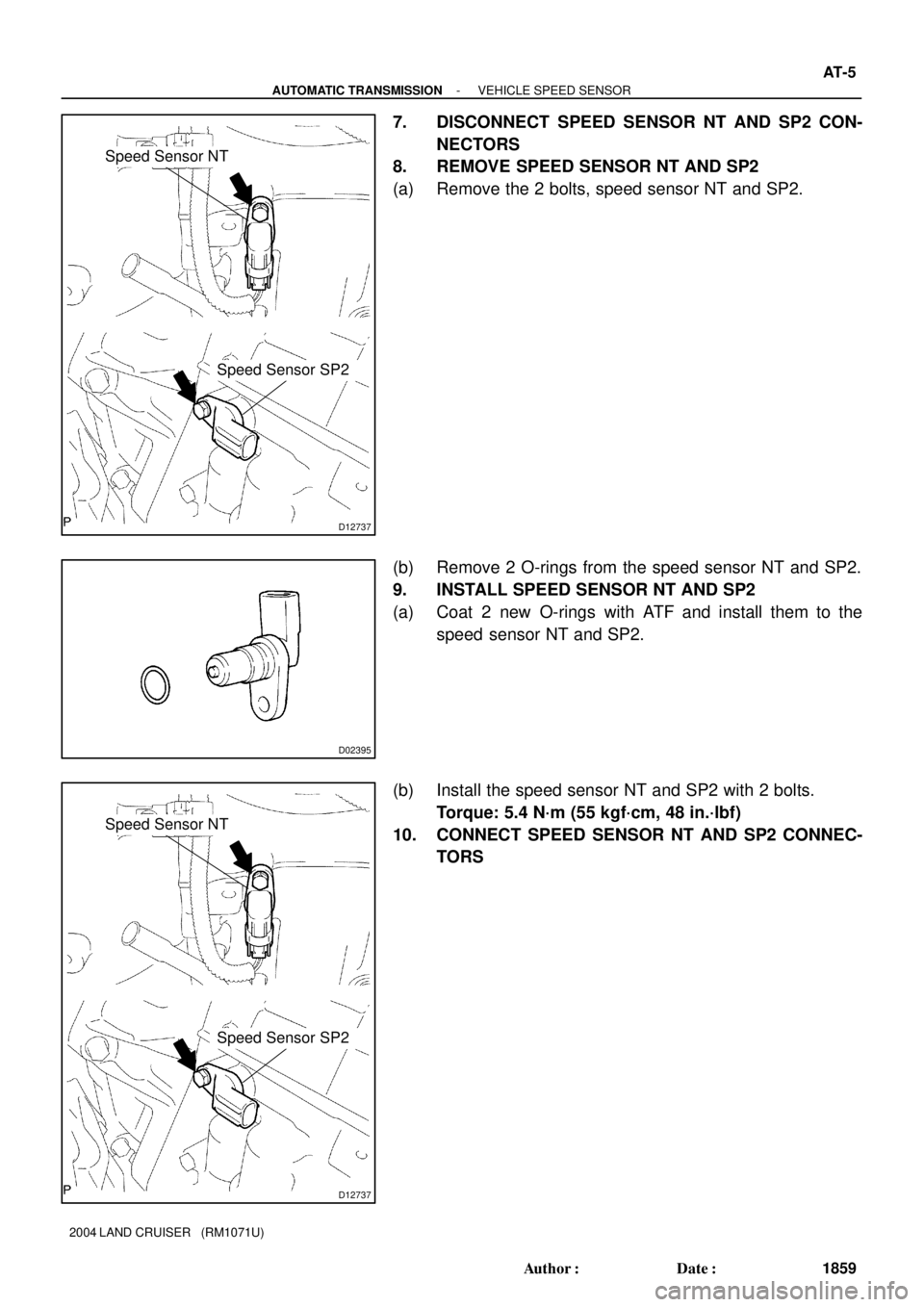
7. DISCONNECT SPEED SENSOR NT AND SP2 CON-
NECTORS
8. REMOVE SPEED SENSOR NT AND SP2
(a) Remove the 2 bolts, speed sensor NT and SP2.
(b) Remove 2 O-rings from the speed sensor NT and SP2.
9. INSTALL SPEED SENSOR NT AND SP2
(a) Coat 2 new O-rings with ATF and install them to the
speed sensor NT and SP2.
(b) Install the speed sensor NT and SP2 with 2 bolts.
Torque: 5.4 N´m (55 kgf´cm, 48 in.´lbf)
10. CONNECT SPEED SENSOR NT AND SP2 CONNEC-
TORS
Page 178 of 3115

Transmission
Error DC 01 *4
(Communication
Control)Transmission to component shown
by auxiliary code has been failed.
(Detecting this DTC does not nec-
essary mean actual failure.)� If same auxiliary code is recorded
in other component, check harness
for power supply and communica-
tion system of components shown
sub code.
Master Reset
(Momentary
Interruption) DD 01 *3
(Communication
Control)After engine is started, radio receiv-
er assembly assembly was discon-
nected from system.� If this error occurs frequently, re-
place radio receiver assembly.
Slave Reset
(Momentary
Interruption) DE 01 *3
(Communication
Control)After engine is started, slave com-
ponent was disconnected from sys-
tem.� Check harness for power supply
of component shown by auxiliary
code.
� Check harness for communica-
tion system of component shown by
auxiliary code.
Master Error DF 01 *4
(Communication
Control)Due to defective condition of radio
receiver assembly, master function
is switched to audio equipment.
Error occurs in communication be-
tween sub-master (audio) and ra-
dio receiver assembly.� Check harness for power supply
of radio receiver assembly.
� Check harness for communica-
tion system of radio receiver as-
sembly .
� Check harness for communica-
tion system between radio receiver
assembly and sub-master compo-
nent.
Registration
Completion
Instruction
Error E0 01
(Communication
Control)ºRegistration Completion Instruc-
tionº command from radio receiver
assembly cannot be received.� Since this DTC is provided for en-
gineering purpose, it may be de-
tected when no actual failure exists.
Audio
processor ON
error E1
01 *2
(Communication
Control)While source equipment is operat-
ing, AMP output is stopped.� Check harness for power supply
of radio receiver assembly.
� Check harness for communica-
tion system of radio receiver as-
sembly.
ON/OFF
Instruction
Parameter
Error E2 01
(Communication
Control)Error occurs in ON/OFF controlling
command from radio receiver as-
sembly assembly.� Replace radio receiver assembly
.
Registration
Request
Transmission E3 01
(Communication
Control)Registration Request command is
output from slave component.
Receiving Connection Check
Instruction, Registration Request
command is output from sub-mas-
ter component.� Since this DTC is provided for en-
gineering purpose, it may be de-
tected when no actual failure exists.
Plural Frame
Abort E4 01
(Communication
Control)� Since this DTC is provided for en-
gineering purpose, it may be de-
tected when no actual failure exists. Plural frame transmission is
aborted.
AM Tuner Error 43 60
(Radio receiver
assembly)Replace radio receiver assembly. Abnormal condition is detected in
AM tuner.
Inspect radio receiver assembly.
FM Tuner Error 44
60
(Radio receiver
assembly)Replace radio receiver assembly. Abnormal condition is detected in
FM tuner.
BE-142
- BODY ELECTRICALAUDIO SYSTEM
2515 Author�: Date�:
2004 LAND CRUISER (RM1071U)
Page 180 of 3115

01*6
(Communica-
tion Control)D7 Connection
Check ErrorComponent in which this code is re-
corded has been disconnected from
system after engine start.
Or, when this code was recorded,
radio receiver assembly was dis-
connected.� Check harness for power supply of
radio receiver assembly.
� Check harness for communication
system of radio receiver assembly.
� Check harness for power supply of
stereo component amplifier.
� Check harness for communication
system of stereo component ampli-
fier.
Transmission
Error DC
*2 01
(Communication
Control)Transmission to component shown
by auxiliary code has bee failed.
(This code does not necessarily
mean actual failure.)If same auxiliary code is recorded in
other component(s), check harness
for power supply and communica-
tion system of components shown
sub code.
Master Reset
(Momentary
Interruption) DD
*3 01
(Communication
Control)� Check harness for power supply
of radio receiver assembly.
� Check harness for communica-
tion system of radio receiver as-
sembly.
� If error occurs frequently, replace
radio receiver assembly.
Registration
Completion
Instruction
Error E0
*1 01
(Communication
Control)ºRegistration Completion Instruc-
tionº command fromradio receiver
assembly cannot be received.Since this DTC is provided for engi-
neering, it may be detected when
no actual failure exists.
ON/OFF
Instruction
Parameter
Error E2 01
(Communication
Control)Error is detected in ON/OFF control
command from radio receiver as-
sembly.Replace radio receiver assembly.
Registration
Request
Transmission E3 01
(Communication
Control)Since this DTC is provided for engi-
neering, it may be detected when
no actual failure exists. � Registration Request command
is output from slave component.
� By reception of connection check
Instruction, Registration Request
command is output from sub-mas-
ter component.After engine is started, radio receiv-
er assembly assembly was discon-
nected from system.
Master Error DF
*4 01
(Communication
Control)Due to defective condition of com-
ponent with a display, master func-
tion is switched to audio equip-
ment . Error occurs in communica-
tion between sub-master (audio)
and master component.� Check harness for power supply
of radio receiver assembly.
� Check harness for communica-
tion system of radio receiver as-
sembly.
� Check harness for communica-
tion system between radio receiver
assembly and sub-master compo-
nent.
Audio proces-
sor ON error E1
*1 01
(Communication
Control)While source equipment is operat-
ing, AMP output is stopped.� Check harness for power supply of
radio receiver assembly
� Check harness for communication
system of radio receiver assembly.
Plural Frame
Abort E4 01
(Communication
Control)Plural frame transmission is
aborted.Since this DTC is provided for engi-
neering purpose, it may be detected
when no actual failure exists. BE-144
- BODY ELECTRICALAUDIO SYSTEM
2517 Author�: Date�:
2004 LAND CRUISER (RM1071U)