Page 565 of 3115

F02832
BR-56
- BRAKEHYDRAULIC BRAKE BOOSTER
2192 Author�: Date�:
2004 LAND CRUISER (RM1071U)
(5) Press the MAIN push switch for 10 sec., and check
that the fluid surface in the reservoir tank of the hy-
draulic brake booster does not rise up at this time.
If the fluid surface level rises up, replace the hydraulic brake
booster.
NOTICE:
Do not press MAIN push switch for more than 10 sec. When
operating the switch continuously, do it an interval of more
than 20 sec.
(6) Start the engine and run it at idle.
(7) Depress the brake pedal.
(8) Release the parking brake lever and shift the shift
lever to ºLº position.
(9) Once, release the brake pedal. After depressing the
brake pedal with stable force, then push and hold
MAIN push switch.
(10) Check that the right rear wheel rotates.
If the right rear wheel stops, replace the hydraulic brake boost-
er.
(r) Inspect the left rear ABS solenoid.
(1) Turn the selector switch to ºLHº position.
(2) Depress the brake pedal several times and release
the brake pedal when the pump begins rotating.
Wait until the pump stops.
(3) Turn the ignition switch OFF.
(4) Depress the brake pedal with a force of 343 N (35
kgf, 77 lbf), record the fluid surface in the reservoir
tank of the hydraulic brake booster.
(5) Press the MAIN push switch for 10 sec., and check
that the fluid surface in the reservoir tank of the hy-
draulic brake booster does not rise up at this time.
If the fluid surface level rises up, replace the hydraulic brake
booster.
NOTICE:
Do not press MAIN push switch for more than 10 sec. When
operating the switch continuously, do it an interval of more
than 20 sec.
(6) Start the engine and run it at idle.
(7) Depress the brake pedal.
(8) Release the parking brake lever and shift the shift
lever to ºLº position.
(9) Once, release the brake pedal. After depressing the
brake pedal with stable force, then push and hold
MAIN push switch.
(10) Check that the left rear wheel rotates.
If the left rear wheel stops, replace the hydraulic brake booster.
(s) Stop the engine and lower the vehicle.
Page 581 of 3115
BR0JW-03
BR-32
- BRAKEREAR BRAKE CALIPER
2168 Author�: Date�:
2004 LAND CRUISER (RM1071U)
INSTALLATION
Installation is in the reverse order of removal (See page BR-28).
HINT:
�After installation, fill the brake reservoir with brake fluid and bleed brake system (See page BR-4).
�Check for leaks.
Page 587 of 3115
BR0JW-03
BR-32
- BRAKEREAR BRAKE CALIPER
2168 Author�: Date�:
2004 LAND CRUISER (RM1071U)
INSTALLATION
Installation is in the reverse order of removal (See page BR-28).
HINT:
�After installation, fill the brake reservoir with brake fluid and bleed brake system (See page BR-4).
�Check for leaks.
Page 591 of 3115
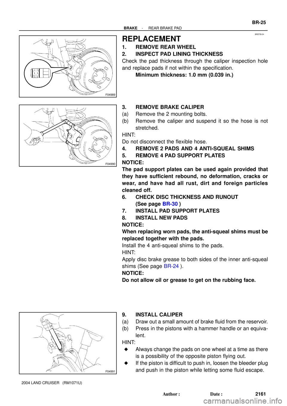
F04989
BR0TB-04
F04990
F04991
- BRAKEREAR BRAKE PAD
BR-25
2161 Author�: Date�:
2004 LAND CRUISER (RM1071U)
REPLACEMENT
1. REMOVE REAR WHEEL
2. INSPECT PAD LINING THICKNESS
Check the pad thickness through the caliper inspection hole
and replace pads if not within the specification.
Minimum thickness: 1.0 mm (0.039 in.)
3. REMOVE BRAKE CALIPER
(a) Remove the 2 mounting bolts.
(b) Remove the caliper and suspend it so the hose is not
stretched.
HINT:
Do not disconnect the flexible hose.
4. REMOVE 2 PADS AND 4 ANTI-SQUEAL SHIMS
5. REMOVE 4 PAD SUPPORT PLATES
NOTICE:
The pad support plates can be used again provided that
they have sufficient rebound, no deformation, cracks or
wear, and have had all rust, dirt and foreign particles
cleaned off.
6. CHECK DISC THICKNESS AND RUNOUT
(See page BR-30)
7. INSTALL PAD SUPPORT PLATES
8. INSTALL NEW PADS
NOTICE:
When replacing worn pads, the anti-squeal shims must be
replaced together with the pads.
Install the 4 anti-squeal shims to the pads.
HINT:
Apply disc brake grease to both sides of the inner anti-squeal
shims (See page BR-24).
NOTICE:
Do not allow oil or grease to get on the rubbing face.
9. INSTALL CALIPER
(a) Draw out a small amount of brake fluid from the reservoir.
(b) Press in the pistons with a hammer handle or an equiva-
lent.
HINT:
�Always change the pads on one wheel at a time as there
is a possibility of the opposite piston flying out.
�If the piston is difficult to push in, loosen the bleeder plug
and push in the piston while letting some fluid escape.
Page 602 of 3115
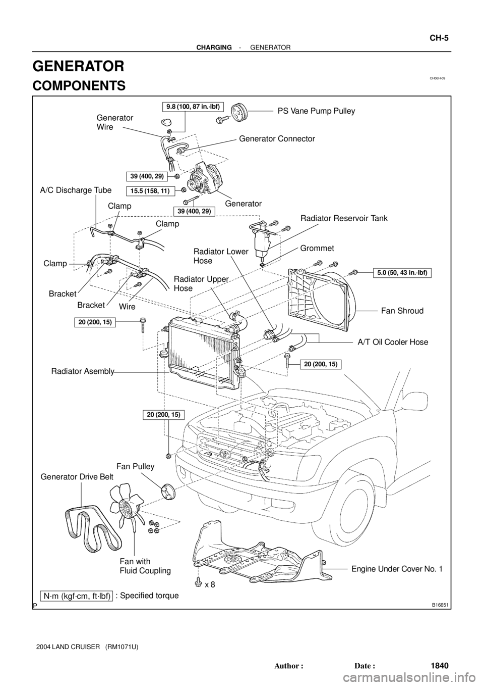
CH06H-09
B16651N´m (kgf´cm, ft´lbf): Specified torque
Radiator Reservoir Tank
Fan Shroud
A/T Oil Cooler Hose Bracket
Fan Pulley
Generator Drive Belt
x 8Engine Under Cover No. 1
BracketWire
A/C Discharge Tube
Clamp
Clamp
Radiator Lower
Hose
Radiator Upper
HoseGrommet
Fan with
Fluid Coupling Radiator Asembly
Clamp
Generator Generator
Wire
Generator ConnectorPS Vane Pump Pulley
9.8 (100, 87 in.´lbf)
39 (400, 29)
15.5 (158, 11)
39 (400, 29)
5.0 (50, 43 in.´lbf)
20 (200, 15)
20 (200, 15)
20 (200, 15)
- CHARGINGGENERATOR
CH-5
1840 Author�: Date�:
2004 LAND CRUISER (RM1071U)
GENERATOR
COMPONENTS
Page 744 of 3115

CO0IO-06
- COOLINGCOOLANT
CO-1
1762 Author�: Date�:
2004 LAND CRUISER (RM1071U)
COOLANT
INSPECTION
HINT:
Check the coolant level when the engine is cold.
1. CHECK ENGINE COOLANT LEVEL AT RADIATOR RESERVOIR
The engine coolant level should be between the ºLOWº and ºFULLº lines at normal temperature
(20°C(68°F)).
If low, check for leaks and add ºToyota Super Long Life Coolantº or similar high quality ethylene glycol based
non-silicate, non-amine, non-nitrite, and non-borate coolant with long-life hybrid organic acid technology
up to the ºFULLº line.
2. CHECK ENGINE COOLANT QUALITY
(a) Remove the radiator cap.
CAUTION:
To avoid the danger of being burned, do not remove the radiator cap while the engine and radiator
are still hot, as fluid and steam can be blown out under pressure.
(b) There should not be any excessive deposits of rust or scale around the radiator cap or radiator filler
hole, and the coolant should be free from oil.
If excessively dirty, clean the coolant passages and replace the coolant.
(c) Reinstall the radiator cap.
Page 745 of 3115

CO0IP-10
B04480Drain PlugDrain Plug Drain Plug
CO-2
- COOLINGCOOLANT
1763 Author�: Date�:
2004 LAND CRUISER (RM1071U)
REPLACEMENT
1. DRAIN ENGINE COOLANT
(a) Remove the radiator cap.
CAUTION:
To avoid the danger of being burned, do not remove the ra-
diator cap while the engine and radiator are still hot, as fluid
and steam can be blown out under pressure.
(b) Remove the 3 drain plugs on the engine and radiator, and
drain the coolant.
(c) Close the 3 drain plugs.
Torque: 12.7 N´m (130 kgf´cm, 9 ft´lbf) for engine
2. REFILL WITH ENGINE COOLANT
(a) Slowly fill the system with coolant.
Capacity:
w/ Front heater: 14.8 liters (15.6 US qts, 13.0 Imp. qts)
w/ Front heater and rear heater:
15.3 liters (16.2 US qts, 13.4 Imp. qts)
NOTICE:
Do not use plain water alone.
HINT:
�Use of improper coolants may damage the engine cooling
system.
�Use ºToyota Super Long Life Coolantº or similar high qual-
ity ethylene glycol based non-silicate, non-amine, non-
nitrite, and non-borate coolant with long-life hybrid or-
ganic acid technology.
�New Toyota vehicles are filled with Toyota Super Long
Life Coolant (color is pink, premixed ethylene glycol con-
centration is approximately 50 % and freezing tempera-
ture is -35°C (-31°F)). When replacing the coolant, Toyo-
ta Super long Life Coolant is recommended.
�Observe the coolant level inside the radiator by pressing
the inlet and outlet radiator hoses several times by hand.
if the coolant level goes down, add the coolant.
If the coolant level goes down, add the coolant.
(b) Install the radiator cap.
(c) Bleed the cooling system.
(1) Start the engine, and open the heater water valve.
(2) Maintain the engine speed at 2,000 - 2,500 rpm,
and warm up the engine.
(d) Stop the engine, and wait until the engine coolant cools
down.
(e) Refill coolant into the reservoir until it is ºFULLº.
3. CHECK FOR ENGINE COOLANT LEAKS
4. CHECK ENGINE COOLANT SPECIFIC GRAVITY COR-
RECTLY
Page 746 of 3115
CO0J0-02
B08313
Radiator Reservoir Tank
Fan Shroud
Radiator AssemblyA/T Oil Cooler Hose
Engine Under Cover No.1
Radiator AssemblyRadiator Upper
HoseRadiator Lower
Hose
Fan Pulley
Generator Drive Belt
x 8 Fan with
Fluid Coupling
RadiatorSide Support
Insulator Support Collar
Side Support12.7 (130, 9)
N´m (kgf´cm, ft´lbf) : Specified torque
5.0 (50, 43in.´lbf )
12.7 (130, 9)
20 (200, 15)
Grommet
A/C Discharge Tube
Wire BracketClamp
Clamp
Bracket Clamp
20 (200, 15)
Bracket
20 (200, 15)
CO-16
- COOLINGRADIATOR
1777 Author�: Date�:
2004 LAND CRUISER (RM1071U)
COMPONENTS