Page 479 of 3115

H04094
A
B
H04098
SST
SST
R13455
10 m (33 ft) or more BO-146
- BODYSEAT BELT PRETENSIONER
2720 Author�: Date�:
2004 LAND CRUISER (RM1071U)
(6) Disconnect the pretensioner connector in the order
ºAº and ºBº as shown in the illustration.
(c) Install the SST.
(1) Connect the 2 SST each other, then connect them
to the seat belt pretensioner.
SST 09082-00700, 09082-00740
NOTICE:
To avoid damaging the SST connector and wire harness,
do not lock secondary lock of the twin lock.
(2) Move the SST to at least 10 m (33 ft) away from the
front of the vehicle.
(3) Close all the doors and windows of the vehicle.
NOTICE:
Take care not to damage the SST wire harness.
(4) Connect the SST red clip to the battery positive (+)
terminal and the black clip to the negative (-) termi-
nal.
(d) Activate seat belt pretensioner.
(1) Confirm that no one is inside the vehicle or within 10
m (33 ft) area around the vehicle.
(2) Press the SST activation switch and activate the
seat belt pretensioner.
HINT:
The seat belt pretensioner operates simultaneously as the LED
of the SST activation switch lights up.
(e) Dispose of the front seat outer belt (with seat belt preten-
sioner).
CAUTION:
�The front seat outer belt is very hot when the seat belt
pretensioner is activated, so leave it alone for at least
30 minutes after activation.
�Use gloves and safety glasses when handling a front
seat outer belt with activated seat belt pretensioner.
�Always wash your hands with water after completing
the operation.
�Do not apply water, etc. to a front seat outer belt with
activated seat belt pretensioner.
2. ACTIVATION WHEN DISPOSING OF FRONT SEAT
OUTER BELT ONLY
Page 481 of 3115

R05181
10 m (33 ft) or more
H04101
BO-148
- BODYSEAT BELT PRETENSIONER
2722 Author�: Date�:
2004 LAND CRUISER (RM1071U)
(d) Activate the seat belt pretensioner.
(1) Connect the SST red clip to the battery positive (+)
terminal and black clip to the battery negative (-)
terminal.
(2) Check that no one is within 10 m (33 ft) area around
the disc wheel.
(3) Press the SST activation switch and activate the
seat belt pretensioner.
HINT:
The seat belt pretensioner operates simultaneously as the LED
of the SST activation switch lights up.
(e) Dispose of the front seat outer belt (with seat belt preten-
sioner).
CAUTION:
�The front seat outer belt is very hot when the seat belt
pretensioner is activated, so leave it alone for at least
30 minutes after activation.
�Use gloves and safety glasses when handling a front
seat outer belt with activated seat belt pretensioner.
�Always wash your hands with water after completing
the operation.
�Do not apply water, etc. to a front seat outer belt with
activated seat belt pretensioner.
(1) Remove the disc wheel and SST.
(2) Place the front seat outer belt in a vinyl bag, tie the
end tightly and dispose of it in the same way as oth-
er general parts disposal.
Page 507 of 3115
H04855
H04856
- BODYUPPER BACK DOOR
BO-23
2597 Author�: Date�:
2004 LAND CRUISER (RM1071U)
11. REMOVE BACK DOOR OUTSIDE HANDLE AS-
SEMBLY
(a) Using a screwdriver, remove the back door outside han-
dle.
HINT:
Tape up the screwdriver tip before use.
(b) Remove the 3 bolts and back door outside handle assem-
bly.
Torque: 5.0 N´m (51 kgf´cm, 44 in.´lbf)
12. REMOVE LICENSE PLATE LIGHTS
13. REMOVE BACK DOOR LOCK
Remove the 4 bolts and back door lock.
Torque: 7.0 N´m (71 ft´lbf, 62 in.´lbf)
14. REMOVE BACK DOOR LINK PROTECTOR
Page 526 of 3115
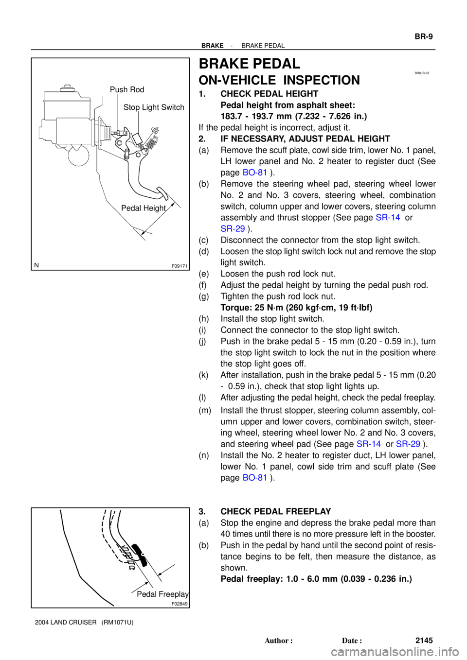
F09171
Stop Light Switch Push Rod
Pedal Height
BR0JB-08
F02849
Pedal Freeplay
- BRAKEBRAKE PEDAL
BR-9
2145 Author�: Date�:
2004 LAND CRUISER (RM1071U)
BRAKE PEDAL
ON-VEHICLE INSPECTION
1. CHECK PEDAL HEIGHT
Pedal height from asphalt sheet:
183.7 - 193.7 mm (7.232 - 7.626 in.)
If the pedal height is incorrect, adjust it.
2. IF NECESSARY, ADJUST PEDAL HEIGHT
(a) Remove the scuff plate, cowl side trim, lower No. 1 panel,
LH lower panel and No. 2 heater to register duct (See
page BO-81).
(b) Remove the steering wheel pad, steering wheel lower
No. 2 and No. 3 covers, steering wheel, combination
switch, column upper and lower covers, steering column
assembly and thrust stopper (See page SR-14 or
SR-29).
(c) Disconnect the connector from the stop light switch.
(d) Loosen the stop light switch lock nut and remove the stop
light switch.
(e) Loosen the push rod lock nut.
(f) Adjust the pedal height by turning the pedal push rod.
(g) Tighten the push rod lock nut.
Torque: 25 N´m (260 kgf´cm, 19 ft´lbf)
(h) Install the stop light switch.
(i) Connect the connector to the stop light switch.
(j) Push in the brake pedal 5 - 15 mm (0.20 - 0.59 in.), turn
the stop light switch to lock the nut in the position where
the stop light goes off.
(k) After installation, push in the brake pedal 5 - 15 mm (0.20
- 0.59 in.), check that stop light lights up.
(l) After adjusting the pedal height, check the pedal freeplay.
(m) Install the thrust stopper, steering column assembly, col-
umn upper and lower covers, combination switch, steer-
ing wheel, steering wheel lower No. 2 and No. 3 covers,
and steering wheel pad (See page SR-14 or SR-29).
(n) Install the No. 2 heater to register duct, LH lower panel,
lower No. 1 panel, cowl side trim and scuff plate (See
page BO-81).
3. CHECK PEDAL FREEPLAY
(a) Stop the engine and depress the brake pedal more than
40 times until there is no more pressure left in the booster.
(b) Push in the pedal by hand until the second point of resis-
tance begins to be felt, then measure the distance, as
shown.
Pedal freeplay: 1.0 - 6.0 mm (0.039 - 0.236 in.)
Page 597 of 3115
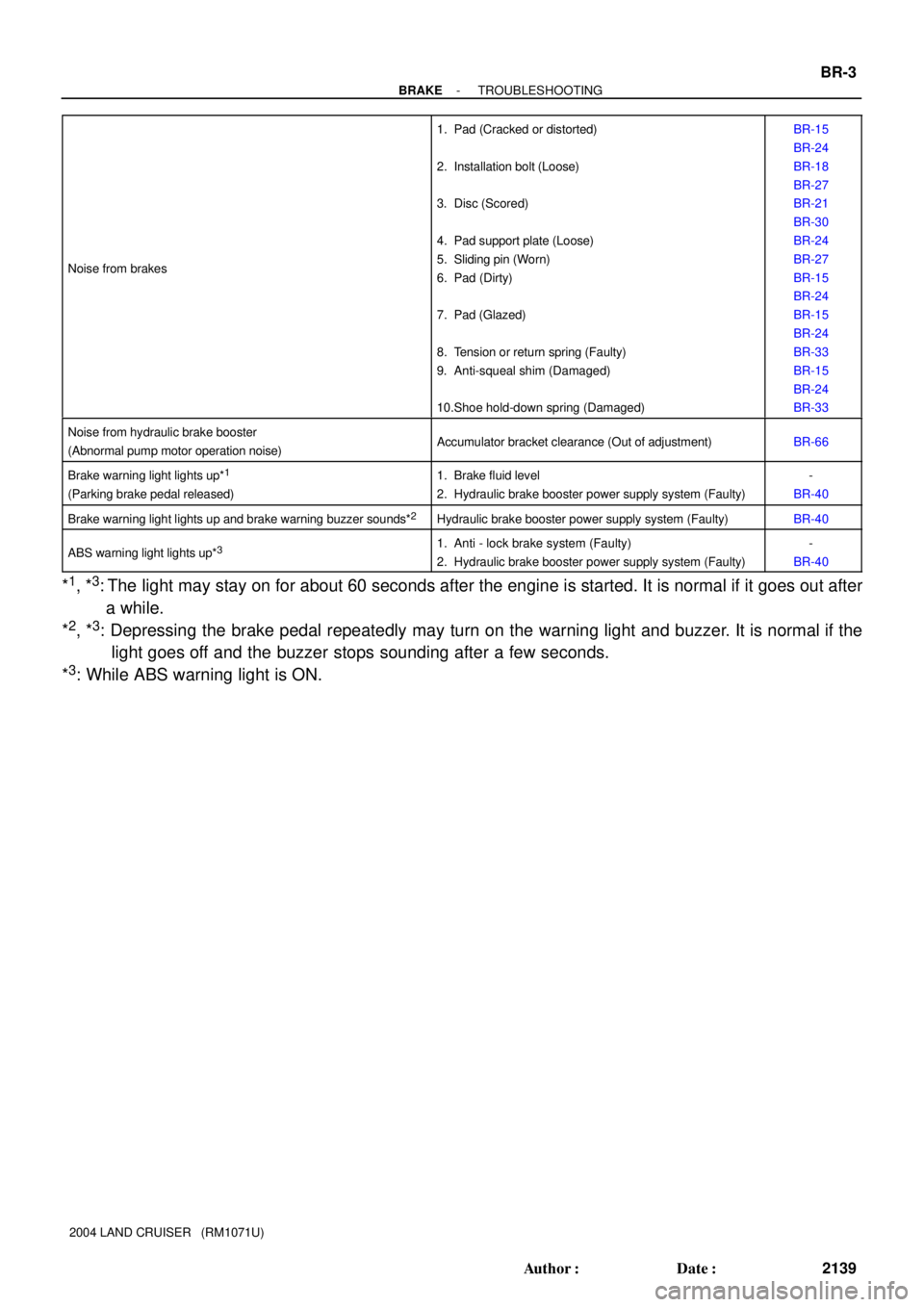
- BRAKETROUBLESHOOTING
BR-3
2139 Author�: Date�:
2004 LAND CRUISER (RM1071U) Noise from brakes
1. Pad (Cracked or distorted)
2. Installation bolt (Loose)
3. Disc (Scored)
4. Pad support plate (Loose)
5. Sliding pin (Worn)
6. Pad (Dirty)
7. Pad (Glazed)
8. Tension or return spring (Faulty)
9. Anti-squeal shim (Damaged)
10.Shoe hold-down spring (Damaged)BR-15
BR-24
BR-18
BR-27
BR-21
BR-30
BR-24
BR-27
BR-15
BR-24
BR-15
BR-24
BR-33
BR-15
BR-24
BR-33
Noise from hydraulic brake booster
(Abnormal pump motor operation noise)Accumulator bracket clearance (Out of adjustment)BR-66
Brake warning light lights up*1
(Parking brake pedal released)
1. Brake fluid level
2. Hydraulic brake booster power supply system (Faulty)-
BR-40
Brake warning light lights up and brake warning buzzer sounds*2Hydraulic brake booster power supply system (Faulty)BR-40
ABS warning light lights up*31. Anti - lock brake system (Faulty)
2. Hydraulic brake booster power supply system (Faulty)-
BR-40
*1, *3: The light may stay on for about 60 seconds after the engine is started. It is normal if it goes out after
a while.
*
2, *3: Depressing the brake pedal repeatedly may turn on the warning light and buzzer. It is normal if the
light goes off and the buzzer stops sounding after a few seconds.
*
3: While ABS warning light is ON.
Page 600 of 3115

Z03473
Ammeter
Disconnect Wire
from Terminal B
Battery
VoltmeterB
Generator CH-4
- CHARGINGCHARGING SYSTEM
1839 Author�: Date�:
2004 LAND CRUISER (RM1071U)
8. CHECK CHARGE WARNING LIGHT CIRCUIT
(a) Warm up the engine and then turn it off.
(b) Switch off all accessories.
(c) Turn the ignition switch ON, and check that the charge
warning light is lit.
(d) Start the engine, and check that the light goes off.
If the light does not go off as specified, troubleshoot the charge
light circuit.
9. INSPECT CHARGING CIRCUIT WITHOUT LOAD
HINT:
If a battery/generator tester is available, connect the tester to
the charging circuit as per manufacturer's instructions.
(a) If a tester is not available, connect a voltmeter and amme-
ter to the charging circuit as follows:
�Disconnect the wire from terminal B of the genera-
tor, and connect it to the negative (-) tester probe
of the ammeter.
�Connect the positive (+) tester probe of the amme-
ter to terminal B of the generator.
�Connect the positive (+) tester probe of the voltme-
ter to terminal B of the generator.
�Ground the negative (-) tester probe of the voltme-
ter.
(b) Check the charging circuit as follows:
With the engine running from idling to 2,000 rpm, check
the reading on the ammeter and voltmeter.
Standard amperage:
10 A or less
Standard voltage:
13.2 - 14.8 V
If the value is not specified, check the generator.
10. INSPECT CHARGING CIRCUIT WITH LOAD
(a) With the engine running at 2,000 rpm, turn on the high
beam headlights and place the heater blower switch at HI.
(b) Check the reading on the ammeter.
Standard amperage:
30 A or more
If the ammeter reading is less than the standard amperage, re-
pair the generator.
HINT:
If the battery is fully charged, the indication will sometimes be
less than standard amperage.
11. REINSTALL ENGINE UNDER COVER NO.1
Page 764 of 3115
F17763
EXI
WT A43
A43 IX1
F15Cowl Side J/B RH
Cowl Side J/B RH Cowl Side J/B RH
Cowl Side J/B LHI18
Ignition SW
Engine Room J/BCombination MeterABS & BA & TRAC
& VSC ECU
SB
D4
Detection SW
(Center Diff. Lock)
2
W-B
P-B
SB
SB
SB MET1
2
47
3E3Q
56 3
3Q
3B
3Q3B J4
J/C
B-R B-R
A
AP-B
L-R
W-R AM2 IG2
76
41 10
2E 2A
1
9
1C1B
2 B-G
ECFL Block
Battery MAIN
EC BR W-R8IX1
VSC OFF
17
C13 C12 C151
103
7
14 26
AM2 DI-624
- DIAGNOSTICSABS & VEHICLE STABILITY CONTROL (VSC) &
BRAKE ASSIST (BA) SYSTEM
817 Author�: Date�:
2004 LAND CRUISER (RM1071U)
DTC Always ON Malfunction in ECU
VSC TRAC Warning Light Circuit
CIRCUIT DESCRIPTION
Always ONThere is a malfunction in the ECU internal circuit.
�Power source circuit
�Skid control ECU
�VSC TRAC warning light circuit
HINT:
If the fail safe function is activated in the VSC system, ºVSC OFFº indicator light lights up.
WIRING DIAGRAM
DICA4-01
Page 767 of 3115
F17718F18533
ABS & BA & TRAC
& VSC ECU
Engine Room J/B Combination Meter
Cowl Side J/B RH
Cowl Side J/B LH
I18
Ignition SW
Cowl Side J/B RHWA 1
A42 4
3A 5
3Q 12
C12
41
2E10
2A
1B91
1C AM2
W-RB-R
C12
C15
ECSB
BR8
IX1 3Q SB7MET
4
3EB-R
B-G
FL Block SB R-L
W-R
76AM2 IG2
J4
J/C
AA
2
F15Battery 1 10
MAIN ABS
- DIAGNOSTICSABS & VEHICLE STABILITY CONTROL (VSC) &
BRAKE ASSIST (BA) SYSTEMDI-627
820 Author�: Date�:
2004 LAND CRUISER (RM1071U)
ABS Warning Light Circuit
CIRCUIT DESCRIPTION
If the ECU detects trouble, it lights the ABS warning light while at the same time prohibiting ABS control. At
this time, the ECU records a DTC in memory.
Connect terminals Tc and E
1 of the DLC1 or Tc and CG of DLC3 to make the ABS warning light blink and
output the DTC.
WIRING DIAGRAM
DICA5-02