Page 420 of 3115
2 Clips
H21279
H18904
- BODYINSTRUMENT PANEL
BO-95
2669 Author�: Date�:
2004 LAND CRUISER (RM1071U)
28. INSTALL CLUSTER FINISH PANEL
Connect the connecter, then install the cluster finish panel.
29. INSTALL STEERING WHEEL
(See page SR-24 or SR-37)
30. INSTALL FRONT PILLAR GARNISH
(a) Install the front pillar garnish.
(b) Use the same manner described above to the other side.
31. INSTALL FRONT ASSIST GRIP
(a) Install the assist grip with the 2 screws, then install the 2
assist grip plugs.
(b) Use the same manner described above to the other side.
32. INSTALL FRONT DOOR OPENING TRIMS
33. INSTALL COWL SIDE TRIMS
34. INSTALL FRONT DOOR SCUFF PLATES
Page 421 of 3115
BO1KN-01
BO-90
- BODYINSTRUMENT PANEL
2664 Author�: Date�:
2004 LAND CRUISER (RM1071U)
REASSEMBLY
Reassembly is in the reverse order of disassembly (See page BO-89).
Page 422 of 3115

BO4IX-01
H20976
H20977
H20975
: 8 Clips
H20978
BO-84
- BODYINSTRUMENT PANEL
2658 Author�: Date�:
2004 LAND CRUISER (RM1071U)
REMOVAL
1. w/ CD Changer Built In The Audio System:
SHIP MODE SETTING
(a) Take out all of the CDs.
NOTICE:
If they cannot be taken out, do not attempt to take out forci-
bly and send the unit for repair.
(b) Turn the ignition switch to ACC as pressing the ºSEEK
UPº and ºDISCº switches at the same time.
HINT:
When the ship mode has been set, ºSHIPº must be displayed.
(c) Turn the ignition switch to OFF and disconnect the battery
negative cable.
NOTICE:
Connecting the battery negative cable automatically end
the ship mode.
2. REMOVE CENTER REGISTER
(a) Using a moulding remover, remove the center register.
(b) Disconnect the connector.
(c) Use the same manner described above to the other side.
3. REMOVE RADIO WITH A/C CONTROL ASSEMBLY
(a) Remove the 4 bolts.
(b) Disconnect the radio with A/C control assembly cable and
remove the radio with A/C control assembly.
4. w/ CD Changer Built In The Audio System:
SHIP MODE CONFIRMATION
Check that a metal can be seen from holes marked ºSHIPº on
the back of the radio with A/C control assembly.
NOTICE:
If a metal cannot be seen from a hole on the back of the ra-
dio with A/C control assembly, repeat ºSHIP MODEº.
5. REMOVE FRONT DOOR SCUFF PLATES
6. REMOVE COWL SIDE TRIMS
7. REMOVE FRONT DOOR OPENING TRIMS
Page 423 of 3115

H18904
H21279
2 Clips
H21283
: 5 Clips
H21657
- BODYINSTRUMENT PANEL
BO-85
2659 Author�: Date�:
2004 LAND CRUISER (RM1071U)
8. REMOVE FRONT ASSIST GRIP
(a) Using a screwdriver, remove the assist grip plugs, then re-
move the 2 screws and assist grip.
HINT:
Tape up the screwdriver tip before use.
(b) Use the same manner described above to the other side.
9. REMOVE FRONT PILLAR GARNISH
(a) Using a screwdriver, remove the front pillar garnish.
HINT:
Tape up the screwdriver tip before use.
(b) Use the same manner described above to the other side.
10. REMOVE STEERING WHEEL
(See page SR-14 or SR-29)
11. REMOVE CLUSTER FINISH PANEL
Using a screwdriver, remove the cluster finish panel, then dis-
connect the connector.
HINT:
Tape up the screwdriver tip before use.
12. REMOVE HOOD LOCK CONTROL CABLE LEVER
AND FUEL LID CONTROL CABLE LEVER
(a) Remove the 2 screws and the hood lock control cable le-
ver.
(b) Remove the 2 screws and the fuel lid control cable lever.
13. REMOVE LOWER NO. 1 PANEL
(a) Remove the screw.
(b) Using a screwdriver, remove the lower No. 1 panel, then
disconnect the connectors.
HINT:
Tape up the screwdriver tip before use.
14. REMOVE LH LOWER PANEL
Remove the 3 bolts and the LH lower panel.
15. REMOVE COLUMN COVERS
Remove the 3 screws and the column covers.
16. REMOVE COMBINATION SWITCH
(a) Disconnect the connectors.
(b) Remove the clamp.
(c) Remove the 4 screws and the combination switch.
Page 424 of 3115
H04808
H21420
H04807
H21418
BO-86
- BODYINSTRUMENT PANEL
2660 Author�: Date�:
2004 LAND CRUISER (RM1071U)
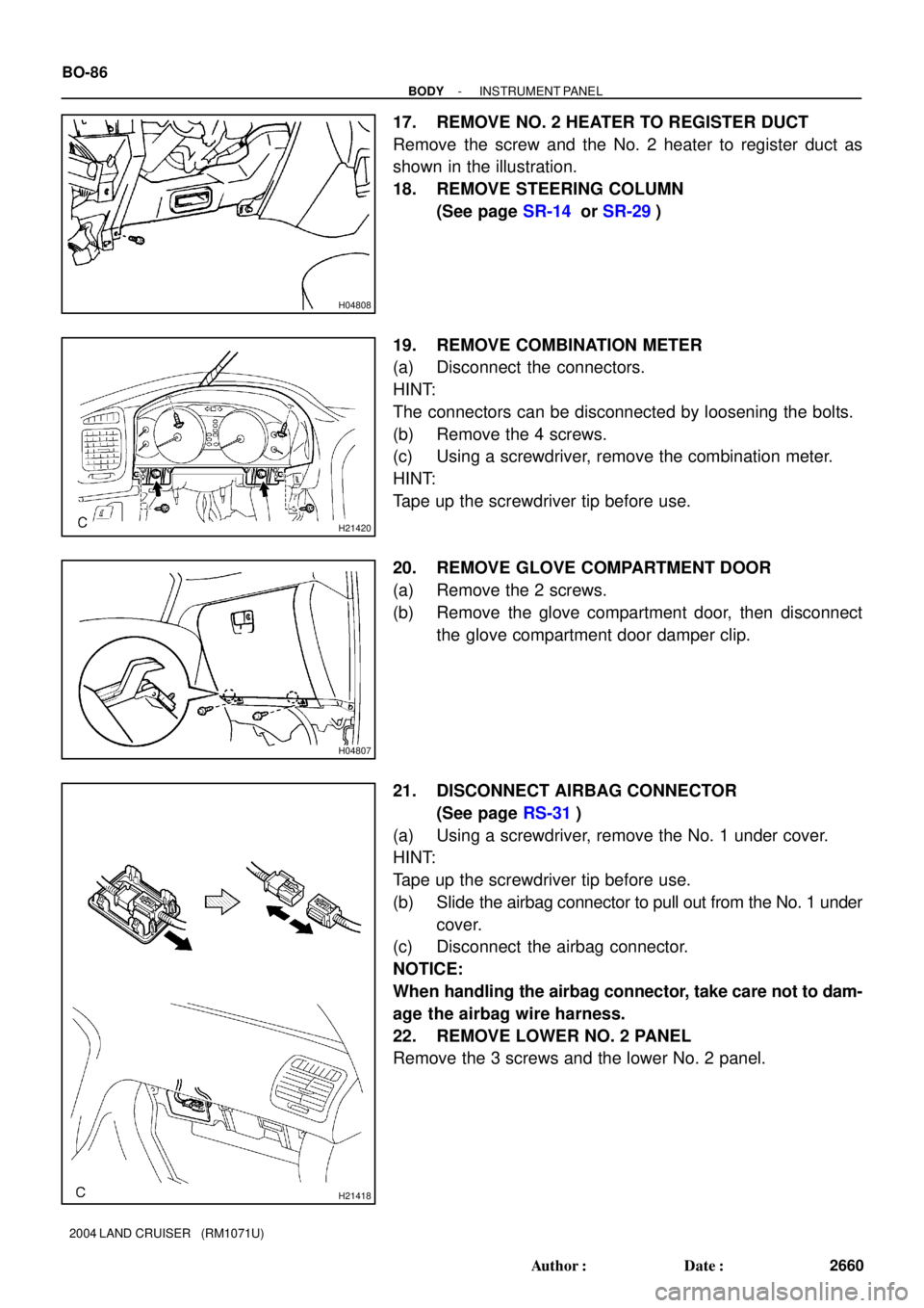
17. REMOVE NO. 2 HEATER TO REGISTER DUCT
Remove the screw and the No. 2 heater to register duct as
shown in the illustration.
18. REMOVE STEERING COLUMN
(See page SR-14 or SR-29)
19. REMOVE COMBINATION METER
(a) Disconnect the connectors.
HINT:
The connectors can be disconnected by loosening the bolts.
(b) Remove the 4 screws.
(c) Using a screwdriver, remove the combination meter.
HINT:
Tape up the screwdriver tip before use.
20. REMOVE GLOVE COMPARTMENT DOOR
(a) Remove the 2 screws.
(b) Remove the glove compartment door, then disconnect
the glove compartment door damper clip.
21. DISCONNECT AIRBAG CONNECTOR
(See page RS-31)
(a) Using a screwdriver, remove the No. 1 under cover.
HINT:
Tape up the screwdriver tip before use.
(b) Slide the airbag connector to pull out from the No. 1 under
cover.
(c) Disconnect the airbag connector.
NOTICE:
When handling the airbag connector, take care not to dam-
age the airbag wire harness.
22. REMOVE LOWER NO. 2 PANEL
Remove the 3 screws and the lower No. 2 panel.
Page 425 of 3115

H18912
: 6 Clips
H18913
: 2 Clips
H20954
H20955
H21406
: 5 Clips
- BODYINSTRUMENT PANEL
BO-87
2661 Author�: Date�:
2004 LAND CRUISER (RM1071U)
23. REMOVE FRONT CONSOLE PANEL
(a) Remove the transfer shift lever knob.
(b) Using a screwdriver, remove the front console panel.
HINT:
Tape up the screwdriver tip before use.
24. REMOVE CONSOLE REAR END PANEL
(a) Remove the rear console cup holder box.
(b) Remove the 2 screws.
(c) Using a screwdriver, remove the console rear end panel.
HINT:
Tape up the screwdriver tip before use.
25. REMOVE REAR RADIO CONTROL PANEL
Disconnect the connector, then remove the 3 screws and the
rear radio control panel.
26. REMOVE REAR CONSOLE BOX
(a) w/o Disc player changer :
Remove the 6 bolts, the 8 screws and the rear console
box.
(b) w/ Disc player changer :
Remove the 4 bolts, the 8 screws and the rear console
box.
27. REMOVE CENTER LOWER CLUSTER FINISH PANEL
Using a screwdriver, remove the center lower cluster finish pan-
el, then disconnect the connector.
HINT:
Tape up the screwdriver tip before use.
Page 426 of 3115
H18914
H18915
BO-88
- BODYINSTRUMENT PANEL
2662 Author�: Date�:
2004 LAND CRUISER (RM1071U)
28. REMOVE FRONT CONSOLE BOX AND FRONT CON-
SOLE BOX BRACKET
Remove the 2 bolts, the front console box and the front console
box bracket.
29. REMOVE INSTRUMENT PANEL
(a) Disconnect the junction connectors.
HINT:
The connectors can be disconnected by loosening the bolts.
(b) Disconnect the connector, then remove the 8 bolts, the 2
nuts and the instrument panel.
30. REMOVE ECM (See page SF-60)
31. REMOVE NO. 3 HEATER TO REGISTER DUCT
32. REMOVE NO. 4 HEATER TO REGISTER DUCT
33. REMOVE GLOVE COMPARTMENT DOOR DAMPER
34. REMOVE FLOOR BRACE
35. REMOVE NO. 1 BRACE
36. REMOVE REINFORCEMENT
Page 1025 of 3115
DIDYQ-01
FI0534
- DIAGNOSTICSAUTOMATIC TRANSMISSION
DI-361
554 Author�: Date�:
PRE-CHECK
1. DIAGNOSIS SYSTEM
(a) Description
(1) When troubleshooting OBD II vehicles, the only dif-
ference from the usual troubleshooting procedure
is that you need to connect an OBD II scan tool com-
plying with SAE J1987 or a hand-held tester to the
vehicle, and read off various data output from the
vehicle's ECM.
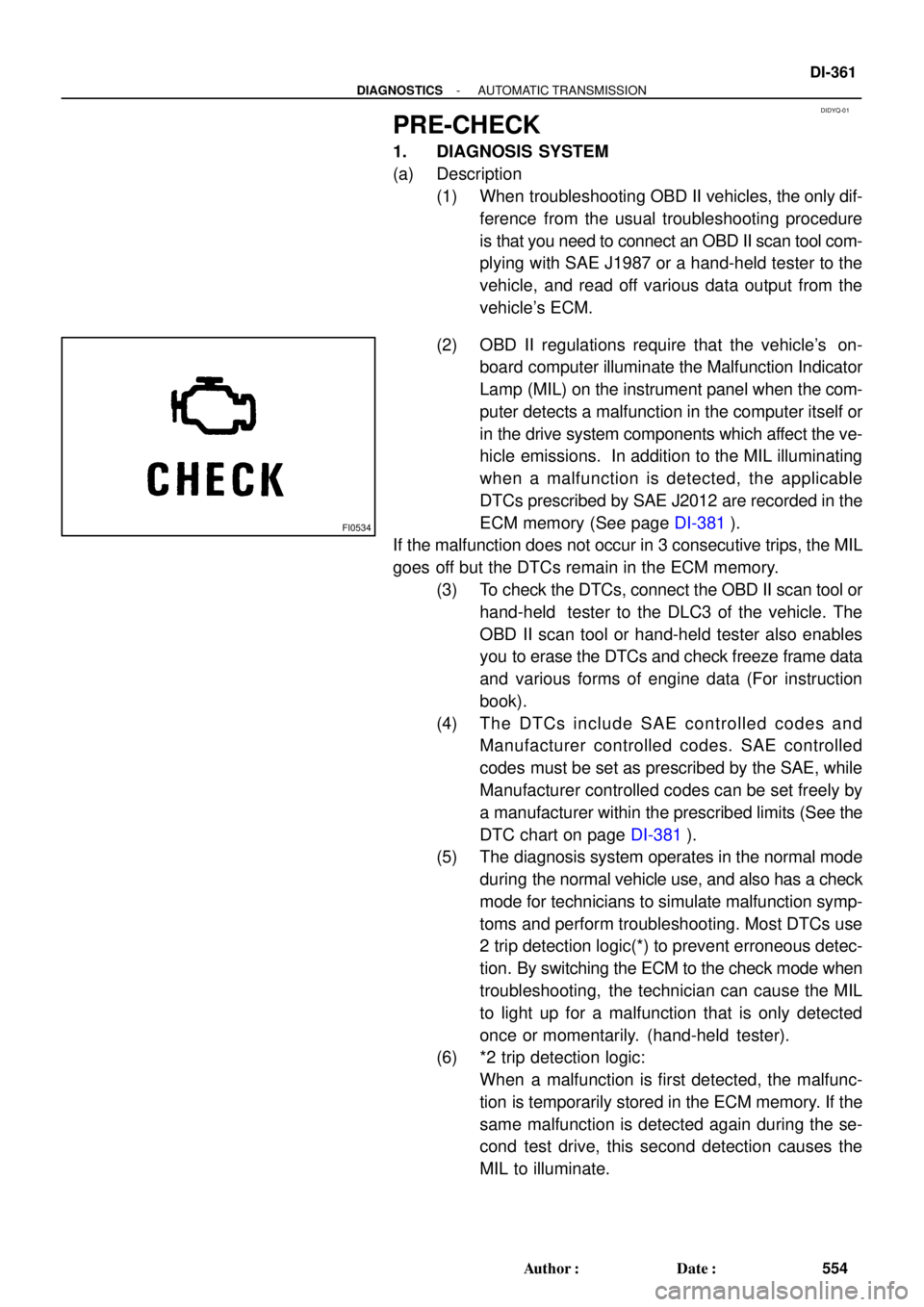
(2) OBD II regulations require that the vehicle's on-
board computer illuminate the Malfunction Indicator
Lamp (MIL) on the instrument panel when the com-
puter detects a malfunction in the computer itself or
in the drive system components which affect the ve-
hicle emissions. In addition to the MIL illuminating
when a malfunction is detected, the applicable
DTCs prescribed by SAE J2012 are recorded in the
ECM memory (See page DI-381).
If the malfunction does not occur in 3 consecutive trips, the MIL
goes off but the DTCs remain in the ECM memory.
(3) To check the DTCs, connect the OBD II scan tool or
hand-held tester to the DLC3 of the vehicle. The
OBD II scan tool or hand-held tester also enables
you to erase the DTCs and check freeze frame data
and various forms of engine data (For instruction
book).
(4) The DTCs include SAE controlled codes and
Manufacturer controlled codes. SAE controlled
codes must be set as prescribed by the SAE, while
Manufacturer controlled codes can be set freely by
a manufacturer within the prescribed limits (See the
DTC chart on page DI-381).
(5) The diagnosis system operates in the normal mode
during the normal vehicle use, and also has a check
mode for technicians to simulate malfunction symp-
toms and perform troubleshooting. Most DTCs use
2 trip detection logic(*) to prevent erroneous detec-
tion. By switching the ECM to the check mode when
troubleshooting, the technician can cause the MIL
to light up for a malfunction that is only detected
once or momentarily. (hand-held tester).
(6) *2 trip detection logic:
When a malfunction is first detected, the malfunc-
tion is temporarily stored in the ECM memory. If the
same malfunction is detected again during the se-
cond test drive, this second detection causes the
MIL to illuminate.