Page 350 of 3115
I01272
2
1
I25793
- BODY ELECTRICALWIPER AND WASHER SYSTEM
BE-55
2428 Author�: Date�:
2004 LAND CRUISER (RM1071U)
10. INSPECT REAR WASHER MOTOR OPERATION
Connect the positive (+) lead from the battery to terminal 2 and
the negative (-) lead to terminal 1, check that the motor oper-
ates.
NOTICE:
These tests must be performed quickly (within 20 seconds) to
prevent the coil from burning out.
If operation is not as specified, replace the motor.
11. INSPECT REAR WIPER RELAY CONTINUITY
Switch positionTester connectionSpecified condition
OFF--
INT1 - 4 - 6Continuity
LO3 - 5 - 6Continuity
Wash23 - 5 - 6Continuity
If continuity is not as specified, replace the relay.
Page 538 of 3115
- BRAKEFRONT BRAKE PAD
BR-17
2153 Author�: Date�:
2004 LAND CRUISER (RM1071U)
NOTICE:
There should be no oil or grease adhering to the friction
surfaces of the pads or the disc.
8. INSTALL 2 PAD RETAINER CLIPS AND 2 PINS
9. INSTALL CLIP
10. INSTALL FRONT WHEEL
Torque: 103 N´m (1,050 kgf´cm, 76 ft´lbf)
11. DEPRESS BRAKE PEDAL SEVERAL TIMES
12. CHECK THAT FLUID LEVEL IS AT MAX LINE
Page 591 of 3115

REPLACEMENT
1. REMOVE REAR WHEEL
2. INSPECT PAD LINING THICKNESS
Check the pad thickness th")
F04989
BR0TB-04
F04990
F04991
- BRAKEREAR BRAKE PAD
BR-25
2161 Author�: Date�:
2004 LAND CRUISER (RM1071U)
REPLACEMENT
1. REMOVE REAR WHEEL
2. INSPECT PAD LINING THICKNESS
Check the pad thickness through the caliper inspection hole
and replace pads if not within the specification.
Minimum thickness: 1.0 mm (0.039 in.)
3. REMOVE BRAKE CALIPER
(a) Remove the 2 mounting bolts.
(b) Remove the caliper and suspend it so the hose is not
stretched.
HINT:
Do not disconnect the flexible hose.
4. REMOVE 2 PADS AND 4 ANTI-SQUEAL SHIMS
5. REMOVE 4 PAD SUPPORT PLATES
NOTICE:
The pad support plates can be used again provided that
they have sufficient rebound, no deformation, cracks or
wear, and have had all rust, dirt and foreign particles
cleaned off.
6. CHECK DISC THICKNESS AND RUNOUT
(See page BR-30)
7. INSTALL PAD SUPPORT PLATES
8. INSTALL NEW PADS
NOTICE:
When replacing worn pads, the anti-squeal shims must be
replaced together with the pads.
Install the 4 anti-squeal shims to the pads.
HINT:
Apply disc brake grease to both sides of the inner anti-squeal
shims (See page BR-24).
NOTICE:
Do not allow oil or grease to get on the rubbing face.
9. INSTALL CALIPER
(a) Draw out a small amount of brake fluid from the reservoir.
(b) Press in the pistons with a hammer handle or an equiva-
lent.
HINT:
�Always change the pads on one wheel at a time as there
is a possibility of the opposite piston flying out.
�If the piston is difficult to push in, loosen the bleeder plug
and push in the piston while letting some fluid escape.
Page 596 of 3115

TROUBLESHOOTING
PROBLEM SYMPTOMS TABLE
Use the table below to help you find the cause of the problem. The number")
BR0JA-17
BR-2
- BRAKETROUBLESHOOTING
2138 Author�: Date�:
2004 LAND CRUISER (RM1071U)
TROUBLESHOOTING
PROBLEM SYMPTOMS TABLE
Use the table below to help you find the cause of the problem. The numbers indicate the priority of the likely
cause of the problem. Check each part in order. If necessary, replace these parts.
SymptomSuspect AreaSee page
Low pedal or spongy pedal
1. Fluid leaks for brake system
2. Air in brake system
3. Piston seals (Worn or damaged)
4. Hydraulic brake booster (Faulty)DI-655
BR-4
BR-18
BR-27
BR-40
Brake drags
1. Brake pedal freeplay (Minimum)
2. Parking brake lever travel (Out of adjustment)
3. Parking brake wire (Sticking)
4. Parking brake (Shoe clearance out of adjustment)
5. Pad (Cracked or distorted)
6. Piston (Stuck)
7. Piston (Frozen)
8. Tension or return spring (Faulty)
9. Hydraulic brake booster (Faulty)BR-9
BR-14
-
BR-33
BR-15
BR-24
BR-18
BR-27
BR-18
BR-27
BR-33
BR-40
Brake pulls
1. Piston (Stuck)
2. Pad (Cracked or distorted)
3. Piston (Frozen)
4. Disc (Scored)
5. Hydraulic brake booster (Faulty)BR-18
BR-27
BR-15
BR-24
BR-18
BR-27
BR-21
BR-30
BR-40
Hard pedal but brake inefficient
1. Fluid leaks for brake system
2. Air in brake system
3. Pad (Worn)
4. Pad (Cracked or distorted)
5. Pad (Oily)
6. Pad (Glazed)
7. Disc (Scored)
8. Hydraulic brake booster (Faulty)DI-655
BR-4
BR-15
BR-24
BR-15
BR-24
BR-15
BR-24
BR-15
BR-24
BR-21
BR-30
BR-40
Page 604 of 3115
CH06J-03
B16654
B16655
B16362
B16369SST (B)
SST (A)
Turn
B16371
SST (C)
SST (B)
Insert
CH-8
- CHARGINGGENERATOR
1843 Author�: Date�:
2004 LAND CRUISER (RM1071U)
DISASSEMBLY
1. REMOVE REAR END COVER
(a) Remove the 3 screws and rear end cover.
2. REMOVE END COVER
(a) Remove the 3 nuts and end cover.
(b) Remove the terminal insulator.
3. REMOVE BRUSH HOLDER
(a) Remove the rear seal plate from the brush holder.
(b) Remove the 2 screws and brush holder.
(c) Remove the front seal plate from the coil assembly.
4. REMOVE PULLEY
(a) Hold SST (A) with a torque wrench, and tighten SST (B)
clockwise to the specified torque.
SST 09820-6301 1
Torque: 39 N´m (400 kgf´cm, 29 ft´lbf)
(b) Check that SST (A) is secured to the rotor shaft.
(c) Mount SST (C) in a vise.
(d) Insert SST (B) into SST (C), and attach the pulley nut to
SST (C).
Page 608 of 3115
CH0M6-01
B16368
Pulley
B12276
SST
B16656
B16369
TurnSST (A)
SST (B)
B16371
SST (C)
SST (A)
Insert
- CHARGINGGENERATOR
CH-13
1848 Author�: Date�:
2004 LAND CRUISER (RM1071U)
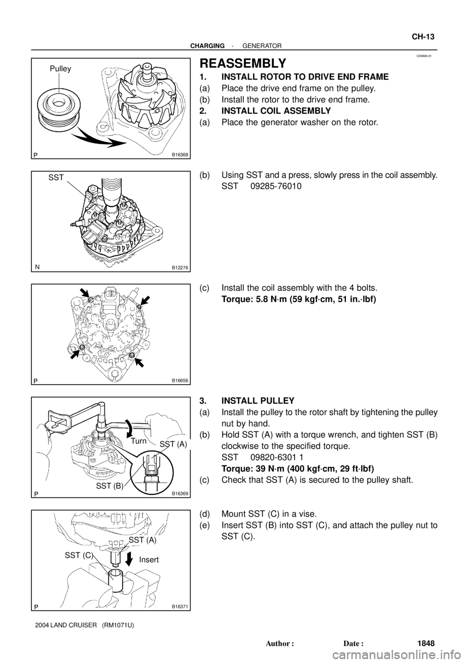
REASSEMBLY
1. INSTALL ROTOR TO DRIVE END FRAME
(a) Place the drive end frame on the pulley.
(b) Install the rotor to the drive end frame.
2. INSTALL COIL ASSEMBLY
(a) Place the generator washer on the rotor.
(b) Using SST and a press, slowly press in the coil assembly.
SST 09285-76010
(c) Install the coil assembly with the 4 bolts.
Torque: 5.8 N´m (59 kgf´cm, 51 in.´lbf)
3. INSTALL PULLEY
(a) Install the pulley to the rotor shaft by tightening the pulley
nut by hand.
(b) Hold SST (A) with a torque wrench, and tighten SST (B)
clockwise to the specified torque.
SST 09820-6301 1
Torque: 39 N´m (400 kgf´cm, 29 ft´lbf)
(c) Check that SST (A) is secured to the pulley shaft.
(d) Mount SST (C) in a vise.
(e) Insert SST (B) into SST (C), and attach the pulley nut to
SST (C).
Page 744 of 3115

COOLANT
INSPECTION
HINT:
Check the coolant level when the engine is cold.
1. CHECK ENGINE COOLANT LEVEL AT RADIATOR RE")
CO0IO-06
- COOLINGCOOLANT
CO-1
1762 Author�: Date�:
2004 LAND CRUISER (RM1071U)
COOLANT
INSPECTION
HINT:
Check the coolant level when the engine is cold.
1. CHECK ENGINE COOLANT LEVEL AT RADIATOR RESERVOIR
The engine coolant level should be between the ºLOWº and ºFULLº lines at normal temperature
(20°C(68°F)).
If low, check for leaks and add ºToyota Super Long Life Coolantº or similar high quality ethylene glycol based
non-silicate, non-amine, non-nitrite, and non-borate coolant with long-life hybrid organic acid technology
up to the ºFULLº line.
2. CHECK ENGINE COOLANT QUALITY
(a) Remove the radiator cap.
CAUTION:
To avoid the danger of being burned, do not remove the radiator cap while the engine and radiator
are still hot, as fluid and steam can be blown out under pressure.
(b) There should not be any excessive deposits of rust or scale around the radiator cap or radiator filler
hole, and the coolant should be free from oil.
If excessively dirty, clean the coolant passages and replace the coolant.
(c) Reinstall the radiator cap.
Page 747 of 3115

INSTALLATION
1. INSTALL SIDE SUPPORTS TO RADIATOR
(a) Install the 2 side support with 8 nuts.
T")
CO0J2-03
B08321
B04475
B08320
- COOLINGRADIATOR
CO-19
1780 Author�: Date�:
2004 LAND CRUISER (RM1071U)
INSTALLATION
1. INSTALL SIDE SUPPORTS TO RADIATOR
(a) Install the 2 side support with 8 nuts.
Torque: 12.7 N´m (130 kgf´cm, 9 ft´lbf)
(b) Install the 2 brackets with the 4 nuts.
Torque: 20 N´m (200 kgf´cm, 13 ft´lbf)
2. INSTALL RADIATOR ASSEMBLY
(a) Place the radiator assembly to the body.
(b) Install the 2 nuts.
Torque: 20 N´m (200 kgf´cm, 15 ft´lbf)
(c) Install the radiator assembly with the 2 bolts to the body.
Torque: 18 N´m (185 kgf´cm, 13 ft´lbf)
3. INSTALL FAN PULLEY, FAN SHROUD, FAN WITH
FLUID COUPLING AND GENERATOR DRIVE BELT
(a) Place the fan with fluid coupling, fan pulley and fan shroud
in position.
(b) Temporarily install the fan pulley mounting nuts.
(c) Install the fan shroud with the 3 bolts.
Torque: 5.0 N´m (50 kgf´cm, 43 in.´lbf)
(d) Connect the A/T oil cooler hoses to the clamp on the fan
shroud.
(e) Install the generator drive belt. (See page CH-16)
(f) Tighten the 4 fan pulley mounting nuts.
(g) Install the 2 brackets on wire to the radiator wire with 2
bolts.
(h) Install the 2 clamps on the A/C discharge tube to the
brackets on the wire with the 2 nuts.
4. INSTALL RADIATOR RESERVOIR
(a) Install the grommet to the reservoir.
(b) Attach the lower side of the reservoir to the fun shuroud.
(c) install the reservoir with the 2 bolts.
(d) Connect the reservoir hose to the radiator.
(e) Install the clamp on the wire to the radiator.
5. CONNECT A/T OIL COOLER HOSES TO RADIATOR
6. CONNECT RADIATOR UPPER HOSE TO RADIATOR
7. CONNECT RADIATOR LOWER HOSE TO RADIATOR
8. FILL WITH ENGINE COOLANT
9. START ENGINE AND CHECK FOR ENGINE COOLANT
LEAKS
10. RECHECK ENGINE COOLANT LEVEL