Page 875 of 3115
F00044
1
2
3 4
(+) (-) Continuity1 2
3 4
1
2
3 4 Open
Continuity
DI-640- DIAGNOSTICSABS & VEHICLE STABILITY CONTROL (VSC) &
BRAKE ASSIST (BA) SYSTEM
833 Author�: Date�:
2004 LAND CRUISER (RM1071U)
INSPECTION PROCEDURE
1 Do the warning lights other than SLIP indicator light come on?
YES Go to step 3.
NO
2 Check IG1 No. 1 relay.
PREPARATION:
Remove the IG1 No. 1 relay from the engine room J/B.
CHECK:
Check continuity between the IG1 No. 1 relay terminals listed
in the table below.
OK:
Terminals 3 and 4Continuity
Terminals 1 and 2Open
CHECK:
(a) Apply battery positive voltage between terminals 3 and 4.
(b) Check continuity between terminals.
OK:
Terminals 1 and 2Continuity
NG Replace IG1 No. 1 relay.
OK
Check for open circuit in harness and connector between IG1 No. 1 relay and combination meter
(See page IN-36).
Page 880 of 3115
F00044
1
2
3 4
(+) (-) Continuity1 2
3 4
1
2
3 4 Open
Continuity
- DIAGNOSTICSABS & VEHICLE STABILITY CONTROL (VSC) &
BRAKE ASSIST (BA) SYSTEMDI-643
836 Author�: Date�:
2004 LAND CRUISER (RM1071U)
INSPECTION PROCEDURE
1 Do the warning lights other than TRAC indicator light come on?
YES Go to step 3.
NO
2 Check IG1 No. 1 relay.
PREPARATION:
Remove the IG1 No. 1 relay from the engine room J/B.
CHECK:
Check continuity between the IG1 No. 1 relay terminals listed
in the table below.
OK:
Terminals 3 and 4Continuity
Terminals 1 and 2Open
CHECK:
(a) Apply battery positive voltage between terminals 3 and 4.
(b) Check continuity between terminals.
OK:
Terminals 1 and 2Continuity
NG Replace IG1 No. 1 relay.
OK
Check for open circuit in harness and connector between IG1 No. 1 relay and combination meter
(See page IN-36).
Page 884 of 3115
F17756
ABS & BA & TRAC
& VSC ECU
Cowl Side J/B RH Cowl Side J/B RH
Cowl Side J/B RH
I18
Ignition SW
Engine Room J/BCowl Side J/B LHCombination Meter
Cowl Side J/B LH
IG1 No.2 Relay
J/B No.2
MAIN
FL Block ECD4 Detection SW
(Center Diff. Lock)
BatteryVSC OFF
IFEC EXI
IG2
IG1
WT A43
A44
A42
A43 IX1
IGN
MET
IG1
AM2
AM1 ECU-IG1
ALTP-B
B-R
B-W
L-R
SB
BR SB
IX1
W-R B-R
SB
B-R
B-R L-B
B-R W-R
W-R
B-G
B-G3
A
AJ4
J/C
C15
C12
C13 3E
3B
3Q3Q
3B
3Q 3B
1C 1B 2A 2E
2E
2E 2B
2C
F1522
6
7 26
14 56
3 SB2
P-B
422
7
2
74
6
1910 41
2
1
5 37
18
391
217 101 W-B
IG2 AM1
AM28 2 1
3
F161
- DIAGNOSTICSABS & VEHICLE STABILITY CONTROL (VSC) &
BRAKE ASSIST (BA) SYSTEMDI-645
838 Author�: Date�:
2004 LAND CRUISER (RM1071U)
VSC OFF Indicator Light, Center Diff Lock Switch Circuit
CIRCUIT DESCRIPTION
This is the VSC control main switch. When the center differential is locked, VSC control goes off and the VSC
OFF indicator light lights up.
WIRING DIAGRAM
DICAA-02
Page 886 of 3115
F00044
1
2
3 4
(+) (-) Continuity1 2
3 4
1
2
3 4 Open
Continuity
- DIAGNOSTICSABS & VEHICLE STABILITY CONTROL (VSC) &
BRAKE ASSIST (BA) SYSTEMDI-647
840 Author�: Date�:
2004 LAND CRUISER (RM1071U)
4 Check IG1 No. 1 relay.
PREPARATION:
Remove the IG1 No. 1 relay from the engine room J/B.
CHECK:
Check continuity between the IG1 No. 1 relay terminals listed
in the table below.
OK:
Terminals 3 and 4Continuity
Terminals 1 and 2Open
CHECK:
(a) Apply battery positive voltage between terminals 3 and 4.
(b) Check continuity between terminals.
OK:
Terminals 1 and 2Continuity
NG Replace IG1 No. 1 relay.
OK
Check for open circuit in harness and connector between IG1 No. 1 relay and combination meter
(See page IN-36).
5 Check VSC OFF indicator light.
Check that the open circuit in the combination meter circuit (See page BE-58).
NG Repair VSC OFF indicator light bulb or combina-
tion meter assembly.
OK
Page 890 of 3115
F00044
1
2
3 4
(+) (-) Continuity1 2
3 4
1
2
3 4 Open
Continuity
- DIAGNOSTICSABS & VEHICLE STABILITY CONTROL (VSC) &
BRAKE ASSIST (BA) SYSTEMDI-633
826 Author�: Date�:
2004 LAND CRUISER (RM1071U)
3 Check IG1 No. 1 relay.
PREPARATION:
Remove the IG1 No. 1 relay from the engine room J/B.
CHECK:
Check continuity between the IG1 No. 1 relay terminals listed
in the table below.
OK:
Terminals 3 and 4Continuity
Terminals 1 and 2Open
CHECK:
(a) Apply battery positive voltage between terminals 3 and 4.
(b) Check continuity between terminals.
OK:
Terminals 1 and 2Continuity
NG Replace IG1 No. 1 relay.
OK
Check for open circuit in harness and connector between IG1 No. 1 relay and combination meter
(See page IN-36).
Page 894 of 3115

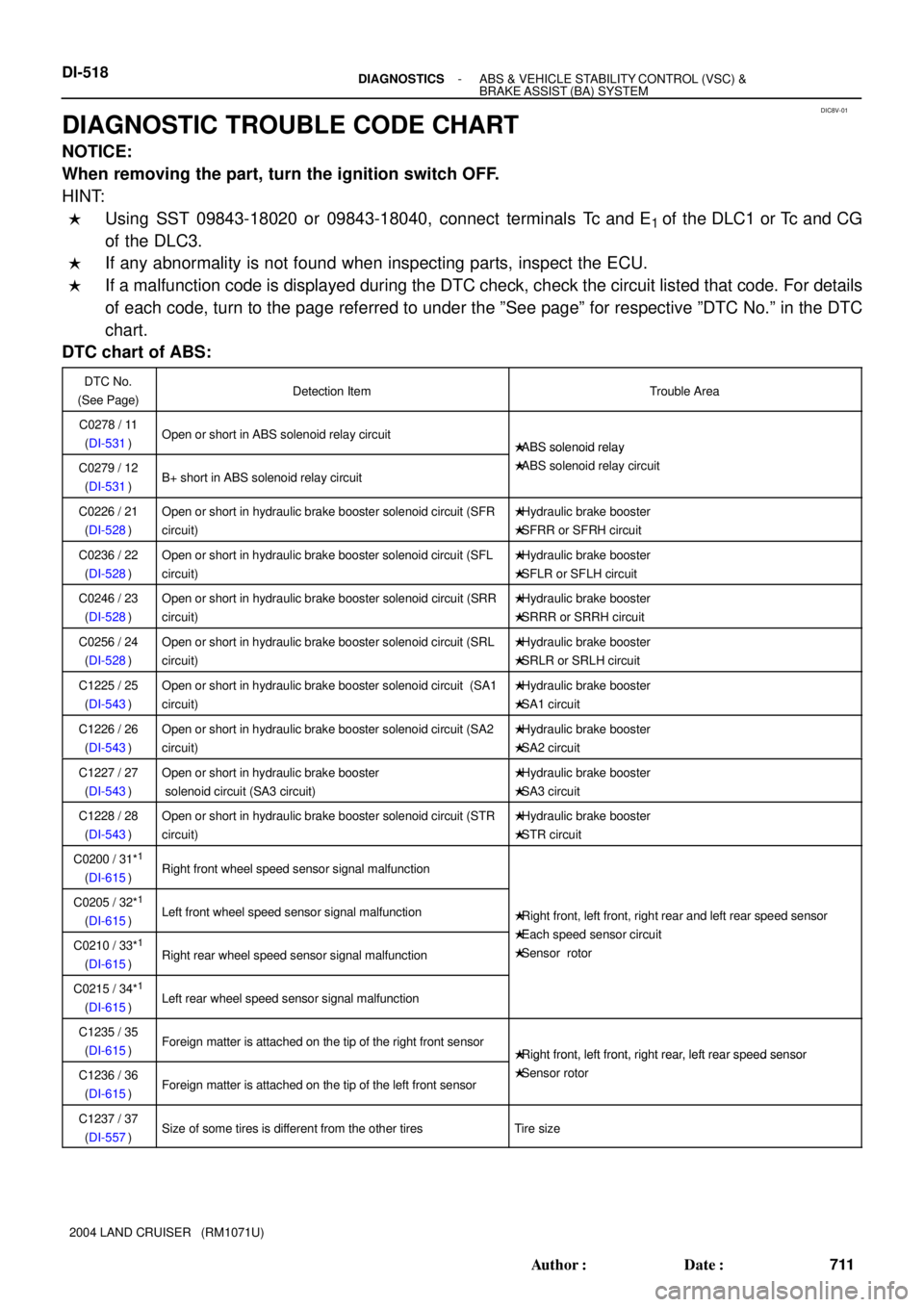
DIC8V-01
DI-518- DIAGNOSTICSABS & VEHICLE STABILITY CONTROL (VSC) &
BRAKE ASSIST (BA) SYSTEM
711 Author�: Date�:
2004 LAND CRUISER (RM1071U)
DIAGNOSTIC TROUBLE CODE CHART
NOTICE:
When removing the part, turn the ignition switch OFF.
HINT:
�Using SST 09843-18020 or 09843-18040, connect terminals Tc and E1 of the DLC1 or Tc and CG
of the DLC3.
�If any abnormality is not found when inspecting parts, inspect the ECU.
�If a malfunction code is displayed during the DTC check, check the circuit listed that code. For details
of each code, turn to the page referred to under the ºSee pageº for respective ºDTC No.º in the DTC
chart.
DTC chart of ABS:
DTC No.
(See Page)Detection ItemTrouble Area
C0278 / 11
(DI-531)Open or short in ABS solenoid relay circuit�ABS solenoid relay
C0279 / 12
(DI-531)B+ short in ABS solenoid relay circuit
�ABS solenoid relay
�ABS solenoid relay circuit
C0226 / 21
(DI-528)Open or short in hydraulic brake booster solenoid circuit (SFR
circuit)�Hydraulic brake booster
�SFRR or SFRH circuit
C0236 / 22
(DI-528)Open or short in hydraulic brake booster solenoid circuit (SFL
circuit)�Hydraulic brake booster
�SFLR or SFLH circuit
C0246 / 23
(DI-528)Open or short in hydraulic brake booster solenoid circuit (SRR
circuit)�Hydraulic brake booster
�SRRR or SRRH circuit
C0256 / 24
(DI-528)Open or short in hydraulic brake booster solenoid circuit (SRL
circuit)�Hydraulic brake booster
�SRLR or SRLH circuit
C1225 / 25
(DI-543)Open or short in hydraulic brake booster solenoid circuit (SA1
circuit)�Hydraulic brake booster
�SA1 circuit
C1226 / 26
(DI-543)Open or short in hydraulic brake booster solenoid circuit (SA2
circuit)�Hydraulic brake booster
�SA2 circuit
C1227 / 27
(DI-543)Open or short in hydraulic brake booster
solenoid circuit (SA3 circuit)�Hydraulic brake booster
�SA3 circuit
C1228 / 28
(DI-543)Open or short in hydraulic brake booster solenoid circuit (STR
circuit)�Hydraulic brake booster
�STR circuit
C0200 / 31*1
(DI-615)Right front wheel speed sensor signal malfunction
C0205 / 32*1
(DI-615)Left front wheel speed sensor signal malfunction�Right front, left front, right rear and left rear speed sensor
Eh d i itC0210 / 33*1
(DI-615)Right rear wheel speed sensor signal malfunction
�Each speed sensor circuit
�Sensor rotor
C0215 / 34*1
(DI-615)Left rear wheel speed sensor signal malfunction
C1235 / 35
(DI-615)Foreign matter is attached on the tip of the right front sensor�Right front, left front, right rear, left rear speed sensor
C1236 / 36
(DI-615)Foreign matter is attached on the tip of the left front sensor
�Right front, left front, right rear, left rear s eed sensor
�Sensor rotor
C1237 / 37
(DI-557)Size of some tires is different from the other tiresTire size
Page 895 of 3115

- DIAGNOSTICSABS & VEHICLE STABILITY CONTROL (VSC) &
BRAKE ASSIST (BA) SYSTEMDI-519
712 Author�: Date�:
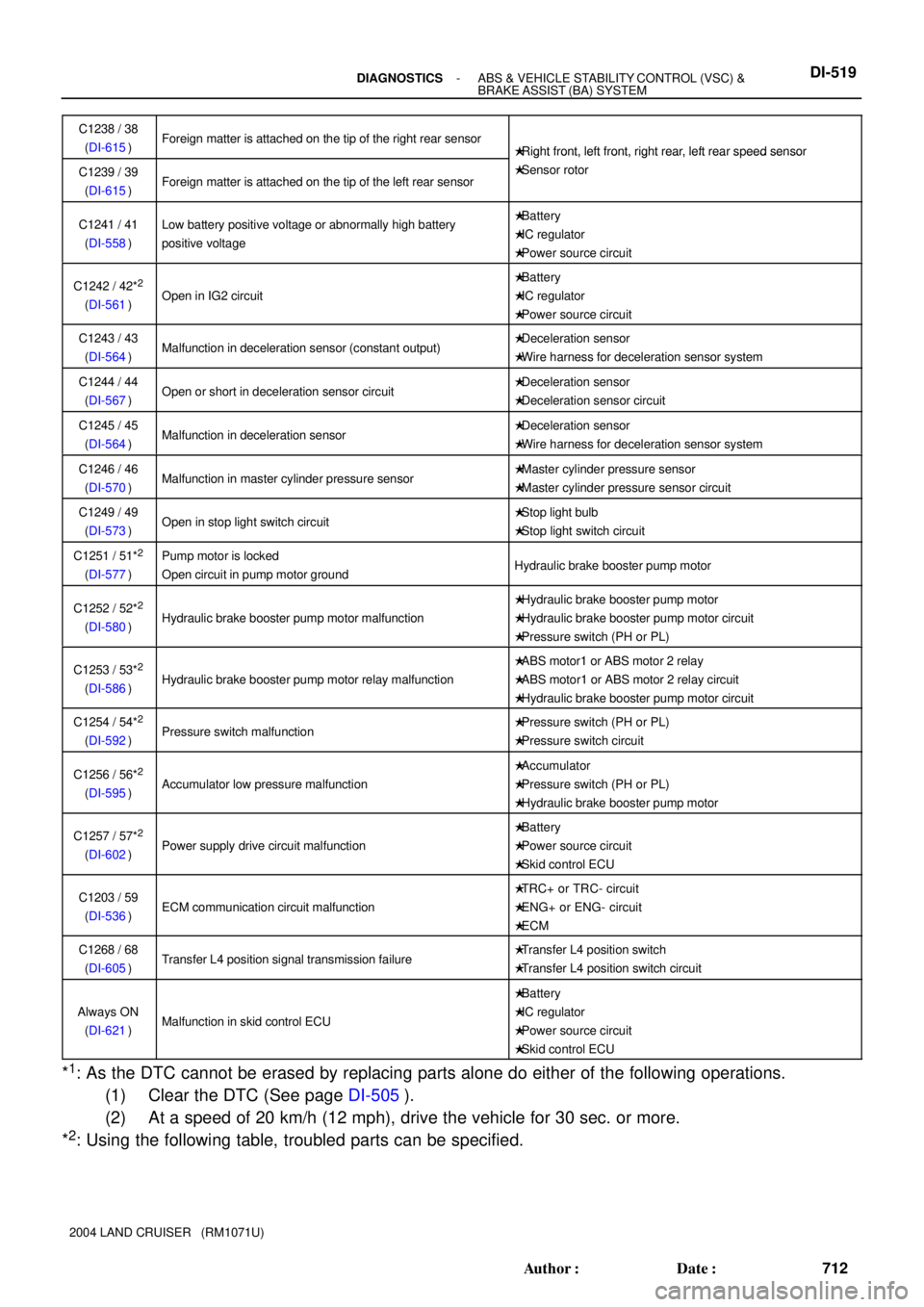
2004 LAND CRUISER (RM1071U)C1238 / 38
(DI-615)
Foreign matter is attached on the tip of the right rear sensor�Right front, left front, right rear, left rear speed sensor
C1239 / 39
(DI-615)Foreign matter is attached on the tip of the left rear sensor
�Right front, left front, right rear, left rear s eed sensor
�Sensor rotor
C1241 / 41
(DI-558)Low battery positive voltage or abnormally high battery
positive voltage�Battery
�IC regulator
�Power source circuit
C1242 / 42*2
(DI-561)Open in IG2 circuit
�Battery
�IC regulator
�Power source circuit
C1243 / 43
(DI-564)Malfunction in deceleration sensor (constant output)�Deceleration sensor
�Wire harness for deceleration sensor system
C1244 / 44
(DI-567)Open or short in deceleration sensor circuit�Deceleration sensor
�Deceleration sensor circuit
C1245 / 45
(DI-564)Malfunction in deceleration sensor�Deceleration sensor
�Wire harness for deceleration sensor system
C1246 / 46
(DI-570)Malfunction in master cylinder pressure sensor�Master cylinder pressure sensor
�Master cylinder pressure sensor circuit
C1249 / 49
(DI-573)Open in stop light switch circuit�Stop light bulb
�Stop light switch circuit
C1251 / 51*2
(DI-577)
Pump motor is locked
Open circuit in pump motor groundHydraulic brake booster pump motor
C1252 / 52*2
(DI-580)Hydraulic brake booster pump motor malfunction
�Hydraulic brake booster pump motor
�Hydraulic brake booster pump motor circuit
�Pressure switch (PH or PL)
C1253 / 53*2
(DI-586)Hydraulic brake booster pump motor relay malfunction
�ABS motor1 or ABS motor 2 relay
�ABS motor1 or ABS motor 2 relay circuit
�Hydraulic brake booster pump motor circuit
C1254 / 54*2
(DI-592)Pressure switch malfunction�Pressure switch (PH or PL)
�Pressure switch circuit
C1256 / 56*2
(DI-595)Accumulator low pressure malfunction
�Accumulator
�Pressure switch (PH or PL)
�Hydraulic brake booster pump motor
C1257 / 57*2
(DI-602)Power supply drive circuit malfunction
�Battery
�Power source circuit
�Skid control ECU
C1203 / 59
(DI-536)ECM communication circuit malfunction
�TRC+ or TRC- circuit
�ENG+ or ENG- circuit
�ECM
C1268 / 68
(DI-605)Transfer L4 position signal transmission failure�Transfer L4 position switch
�Transfer L4 position switch circuit
Always ON
(DI-621)Malfunction in skid control ECU
�Battery
�IC regulator
�Power source circuit
�Skid control ECU
*1: As the DTC cannot be erased by replacing parts alone do either of the following operations.
(1) Clear the DTC (See page DI-505).
(2) At a speed of 20 km/h (12 mph), drive the vehicle for 30 sec. or more.
*
2: Using the following table, troubled parts can be specified.
Page 896 of 3115
ECU
Power source* Hydraulic brake booster Motor relay circuit Accumulator malfunction
Pump motor circuit Pressure switchPH
PL
Pump motor
MTT wire harness
MT+ wire harness
MT- wire harness
MR1 open circuit
MR2 open circuit
MR1 welded contact
MR2 welded contact
Pressure leaks
IG2 open circuit
Power supply circuit
Light Buzzer Light Light Light Light Light LightBuzzer Buzzer Buzzer Buzzer Buzzer Buzzer
DTC
BRAKE warning light and buzzerC1242/42 C1251/51 C1252/52 C1253/53 C1254/54 C1256/56 C1257/57
*: When IG1 circuit is open, the ABS warning light and BRAKE warning light come on.���
��
��
��
��
���
�� �� ��
� � � ��
���
��
��
��
��
� DI-520
- DIAGNOSTICSABS & VEHICLE STABILITY CONTROL (VSC) &
BRAKE ASSIST (BA) SYSTEM
713 Author�: Date�:
2004 LAND CRUISER (RM1071U)
Table of Trouble Part and DTC: