Page 813 of 3115
F17758
Cowl Side J/B LH BatteryEngine Room J/B
Cowl Side J/B LH
Cowl Side J/B RH J4
J/C
Cowl Side J/B LH
IG1 No. 2 Relay
ECU-IG1
AM1
ALT
MAINFL Block
EE IFIG2
IG1
GND4
GND3
GND1
GND2 A44
A42
A42 A42
A41
A41 2A
2B3
13 J/B No. 2
IFF15 F16
2 12C1
2E 2E
2B
3918 37
12
533B 3E22 4IGN2A
2E41 10 1
1C 1B9 AM2
W-R
B-R B-R
B-R B-G
W-R
L-B
B-R
AA
B-G
W-B B-W
W-B
W-B 4
62
7 IG1
AM1
AM2 IG2
W-B
22
6
17
8
31
6 ABS & BA & TRAC
& VSC ECU
W-B
W-B
W-B
W-B
W-B I18
Ignition SW
- DIAGNOSTICSABS & VEHICLE STABILITY CONTROL (VSC) &
BRAKE ASSIST (BA) SYSTEMDI-561
754 Author�: Date�:
2004 LAND CRUISER (RM1071U)
DTC C1242 / 42 IG2 Power Source Circuit
CIRCUIT DESCRIPTION
DTC No.DTC Detecting ConditionTrouble Area
C1242 / 42With the vehicle running, open circuit in IG2 is detected for
more than 7 sec.�Battery
�IC regulator
�Power source circuit
WIRING DIAGRAM
DIC9O-01
Page 829 of 3115

F17712
ABS & BA & TRAC
& VSC Actuator
Engine Room R/B
FL Block
Cowl Side J/B LH
Battery ABS MTR2 Relay
ABS MTR1 RelayMTT A4127
MT+ A4128
MT- A4118
MR2
A442
R2+
A443
W-L
1
1C 1
1 1
2ABS No.2
3 41
2 1
1
1
1B-R
L
GR
Y-B A387
A385
A388
A383
L-R
R
A372
A371
A386
A401
W-BW-BW-B
W-B W-B
EE2A3
IF
GND GND2GND1BM1 BM2 MT- MT+MTT
B-GF152
MAIN
P
R
A41MR1 29 A41
R1+ 1
W-B 43
21ABS & BA & TRAC
& VSC ECU
- DIAGNOSTICSABS & VEHICLE STABILITY CONTROL (VSC) &
BRAKE ASSIST (BA) SYSTEMDI-577
770 Author�: Date�:
2004 LAND CRUISER (RM1071U)
DTC C1251 / 51 Hydraulic Brake Booster Pump Motor
Malfunction
CIRCUIT DESCRIPTION
DTC No.DTC Detecting ConditionTrouble Area
C1251 / 51
Either of the following 1. or 2. is detected:
1. After turning the ignition switch ON, the current of more
than 30 A flows to the motor for more than 1 sec.
2. After turning the ignition switch ON, less than 7 A
change in current is detected more than 3 times in a row
when the motor is ON.
Hydraulic brake booster pump motor
WIRING DIAGRAM
DIC9T-02
Page 832 of 3115
F17712
ABS & BA & TRAC
& VSC ECU ABS & BA & TRAC
& VSC Actuator
Engine Room R/B
FL Block
Cowl Side J/B LH
Battery ABS MTR2 Relay
ABS MTR1 RelayMTT A4127
MT+ A4128
MT- A4118
MR2
A442
R2+
A443
W-L
1
1C 1
1 1
2ABS No.2
3 41
2 1
1
1
1B-R
L
GR
Y-B A387
A385
A388
A383
L-R
R
A372
A371
A386
A401
W-BW-BW-B
W-B W-B
EE2A3
IF
GND GND2GND1BM1 BM2 MT- MT+MTT
B-GF152
MAIN
P
R
A41MR1 29 A41
R1+ 1
W-B 43
21 DI-580
- DIAGNOSTICSABS & VEHICLE STABILITY CONTROL (VSC) &
BRAKE ASSIST (BA) SYSTEM
773 Author�: Date�:
2004 LAND CRUISER (RM1071U)
DTC C1252 / 52 Hydraulic Brake Booster Pump Motor
ON Time Abnormally Long
CIRCUIT DESCRIPTION
DTC No.DTC Detecting ConditionTrouble Area
C1252 / 52After the ignition switch is turned ON, the power is supplied
to the pump motor for more than 5 minutes.�Hydraulic brake booster pump motor
�Hydraulic brake booster pump motor circuit
�Pressure switch (PH or PL)
WIRING DIAGRAM
DIC9U-02
Page 833 of 3115
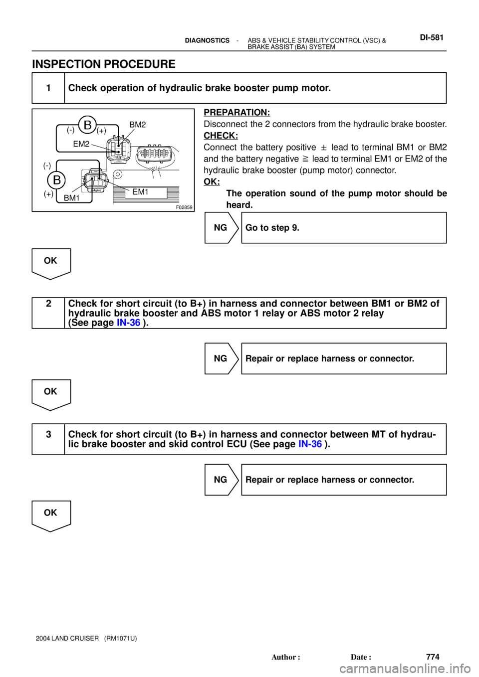
F02859
(-)
(+)
(-)
(+)
BM2
BM1EM1 EM2
- DIAGNOSTICSABS & VEHICLE STABILITY CONTROL (VSC) &
BRAKE ASSIST (BA) SYSTEMDI-581
774 Author�: Date�:
2004 LAND CRUISER (RM1071U)
INSPECTION PROCEDURE
1 Check operation of hydraulic brake booster pump motor.
PREPARATION:
Disconnect the 2 connectors from the hydraulic brake booster.
CHECK:
Connect the battery positive � lead to terminal BM1 or BM2
and the battery negative � lead to terminal EM1 or EM2 of the
hydraulic brake booster (pump motor) connector.
OK:
The operation sound of the pump motor should be
heard.
NG Go to step 9.
OK
2 Check for short circuit (to B+) in harness and connector between BM1 or BM2 of
hydraulic brake booster and ABS motor 1 relay or ABS motor 2 relay
(See page IN-36).
NG Repair or replace harness or connector.
OK
3 Check for short circuit (to B+) in harness and connector between MT of hydrau-
lic brake booster and skid control ECU (See page IN-36).
NG Repair or replace harness or connector.
OK
Page 836 of 3115
 (-) Continuity1 2
3 4
1
2
3 4 Open
Continuity DI-584
- DIAGNOSTICSABS & VEHICLE STABILITY CONTROL (VSC) &
BRAKE ASSIST (BA) SYSTEM
777 Author�: Date�:
2004 LAND CRUISER (RM1071U)")
F00044
1
2
3 4
(+) (-) Continuity1 2
3 4
1
2
3 4 Open
Continuity DI-584
- DIAGNOSTICSABS & VEHICLE STABILITY CONTROL (VSC) &
BRAKE ASSIST (BA) SYSTEM
777 Author�: Date�:
2004 LAND CRUISER (RM1071U)
HINT:
After inspection, connect the connector and clear the DTC (See
page DI-505).
NG Replace hydraulic brake booster assembly.
OK
6 Check for short circuit (to B+) in harness and connector between pressure
switch and skid control ECU (See page IN-36).
NG Repair or replace harness or connector.
OK
7 Check ABS motor 1 relay and ABS motor 2 relay.
PREPARATION:
Remove the ABS motor 1 relay and ABS motor 2 relay from the
engine room J/B.
CHECK:
Check continuity between the motor relay terminals listed in the
table below.
OK:
Terminals 3 and 4Continuity
(Reference value *1)
Terminals 1 and 2Open
*1: ABS motor 1 relay: 54 W
ABS motor 2 relay: 62 W
CHECK:
(a) Apply battery positive voltage between terminals 3 and 4.
(b) Check continuity between terminals.
OK:
Terminals 1 and 2Continuity
Page 837 of 3115
- DIAGNOSTICSABS & VEHICLE STABILITY CONTROL (VSC) &
BRAKE ASSIST (BA) SYSTEMDI-585
778 Author�: Date�:
2004 LAND CRUISER (RM1071U)
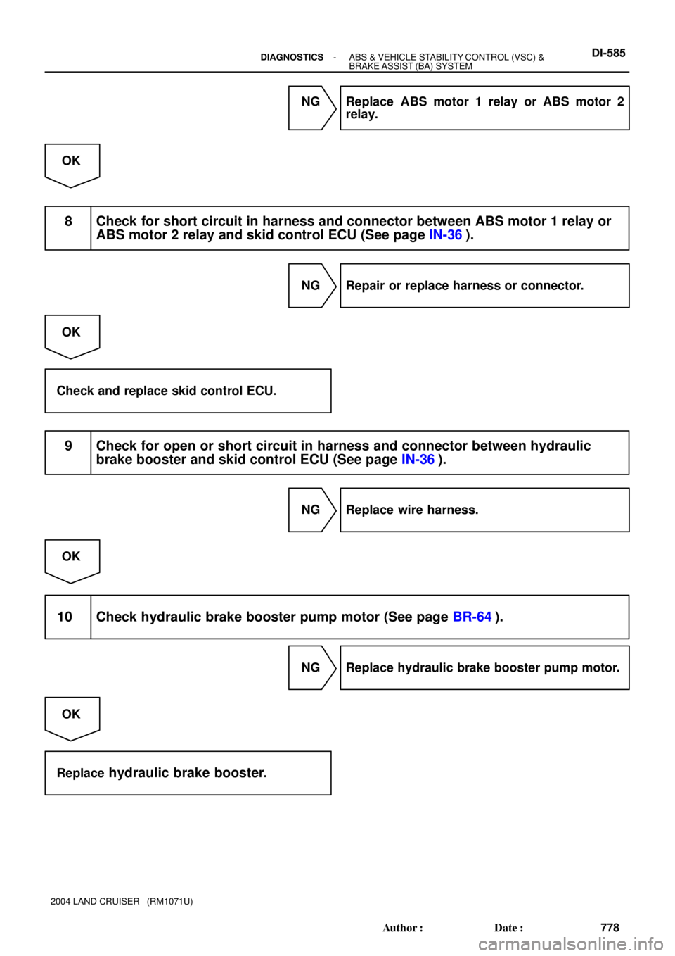
NG Replace ABS motor 1 relay or ABS motor 2
relay.
OK
8 Check for short circuit in harness and connector between ABS motor 1 relay or
ABS motor 2 relay and skid control ECU (See page IN-36).
NG Repair or replace harness or connector.
OK
Check and replace skid control ECU.
9 Check for open or short circuit in harness and connector between hydraulic
brake booster and skid control ECU (See page IN-36).
NG Replace wire harness.
OK
10 Check hydraulic brake booster pump motor (See page BR-64).
NG Replace hydraulic brake booster pump motor.
OK
Replace
hydraulic brake booster.
Page 838 of 3115
 &
BRAKE ASSIST (BA) SYSTEM
779 Author�: Date�:
2004 LAND CRUISER (RM1071U)
DTC C1253 / 53 Motor Relay Circuit
CIRCUIT DESCRIPTION
The ABS mo")
DI-586- DIAGNOSTICSABS & VEHICLE STABILITY CONTROL (VSC) &
BRAKE ASSIST (BA) SYSTEM
779 Author�: Date�:
2004 LAND CRUISER (RM1071U)
DTC C1253 / 53 Motor Relay Circuit
CIRCUIT DESCRIPTION
The ABS motor 1 relay and ABS motor 2 relay supply power to the hydraulic brake booster pump motor.
While the ABS & BA & TRAC & VSC are activated, the ECU switches the motor relay ON and operates the
hydraulic brake booster pump motor.
DTC No.DTC Detecting ConditionTrouble Area
C1253 / 53
When any of the following 1. through 4. is detected:
1. After turning the ignition switch ON, open in the relay
coil is detected for more than 1 sec.
2. When the pressure switch does not control motor
driving, the condition that the motor relay is always ON
continues for more than 1 sec. due to short circuit.
3. When the pressure switch (PH) detects the low
pressure or while the pump motor operates to increase
the pressure, the condition that the motor relay does not
turn ON continues for more than 0.2 sec.
4. When pressure switch does not control motor driving,
the condition that the motor relay is always ON due to
the welded contact continues for more than 2 sec.
�ABS motor 1 or ABS motor 2 relay
�ABS motor 1 or ABS motor 2 relay circuit
�Hydraulic brake booster pump motor circuit
DIC9V-02
Page 839 of 3115
F17712
ABS & BA & TRAC
& VSC ECU ABS & BA & TRAC
& VSC Actuator
Engine Room R/B
FL Block
Cowl Side J/B LH
Battery ABS MTR2 Relay
ABS MTR1 RelayMTT A4127
MT+ A4128
MT- A4118
MR2
A442
R2+
A443
W-L
1
1C 1
1 1
2ABS No.2
3 41
2 1
1
1
1B-R
L
GR
Y-B A387
A385
A388
A383
L-R
R
A372
A371
A386
A401
W-BW-BW-B
W-B W-B
EE2A3
IF
GND GND2GND1BM1 BM2 MT- MT+MTT
B-GF152
MAIN
P
R
A41MR1 29 A41
R1+ 1
W-B 43
21
- DIAGNOSTICSABS & VEHICLE STABILITY CONTROL (VSC) &
BRAKE ASSIST (BA) SYSTEMDI-587
780 Author�: Date�:
2004 LAND CRUISER (RM1071U)
WIRING DIAGRAM