Page 4646 of 6000
6D3–15 STARTING AND CHARGING SYSTEM
Main Data and Specifications
General Specifications
ModelHITACHI GD002350
Rating
Voltage12 V
Output1.4 Kw
Time30 sec
Number of teeth of pinion 9
Rotating direction(as viewed from pinion)Clockwise
Weight(approx.)34 N
No load characteristics
Voltage /Current 11V/90A or less
Speed 2700rpm or more
Load characteristics
Voltage/current 8.4V/250A
Torque 7.3Nꞏm(64lbꞏin.) or more
Speed 1200rpm or more
Locking characteristics
Voltage/current 3V/750A or less
To r q u e19Nꞏm(14lbꞏin) or more
Page 4657 of 6000
6D3–26STARTING AND CHARGING SYSTEM
Main Data and Specifications
General Specifications
Parts Number (Nippon denso)102211—5030
ModelACHD04
Rated voltage12 V
Rated output75 A
Rotating direction (As viewed from pulley)Clockwise
Pulley effective diameter50 mm (1.97 in)
Weight44 N (33 lb)
Page 4662 of 6000
6E–5 ENGINE DRIVEABILITY AND EMISSIONS
Specifications
Tightening Specifications
ApplicationNꞏmLb Ft.Lb In.
Camshaft Position Sensor Retaining Screw9—78
Crankshaft Position Sensor Mounting Bolt10—87
EGR Bolt2821—
EGR Nut2821—
Engine Coolant Temperature Sensor207.7—
Fuel Drain Plug2922—
Fuel Pressure Regulator Attaching Screw6.5—60
Fuel Rail Bolts2518—
Fuel Tank Undercover Retaining Bolts3627—
Heated Oxygen Sensor4231—
Lower Intake Manifold to Engine Block Bolts2518—
Lower Intake Manifold to Engine Block Nuts2518—
Spark Plugs1813—
Throttle Body Mounting Bolts2518—
Upper Intake Manifold to Lower Intake Manifold Bolts2518—
VSS Retaining Bolt13—120
Vehicle Type Specifications
ECAUSTRALIA
THAILAND
SOUTH-EA
ST-ASIA
LATIN
AMERICAGULF
CONTRIES
SAUDI
CHINASOU
TH
AFRI
CA
EXPORTSpecifications
UBSUBSUBSUBSUBSUBS
OBD
O2
SENCATEGRMTATMTATMTATMTATMTMTATOBDSEN
SORAEGR
I21
I21
11
11
11
11
1
1
I
Page 4674 of 6000
6E–17 ENGINE DRIVEABILITY AND EMISSIONS
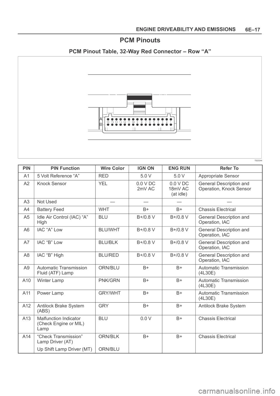
PCM Pinouts
PCM Pinout Table, 32-Way Red Connector – Row “A”
TS23344
PINPIN FunctionWire ColorIGN ONENG RUNRefer To
A15 Volt Reference “A”RED5.0 V5.0 VAppropriate Sensor
A2Knock SensorYEL0.0 V DC
2mV AC0.0 V DC
18mV AC
(at idle)General Description and
Operation, Knock Sensor
A3Not Used————
A4Battery FeedWHTB+B+Chassis Electrical
A5Idle Air Control (IAC) “A”
HighBLUB+/0.8 VB+/0.8 VGeneral Description and
Operation, IAC
A6IAC “A” LowBLU/WHTB+/0.8 VB+/0.8 VGeneral Description and
Operation, IAC
A7IAC “B” LowBLU/BLKB+/0.8 VB+/0.8 VGeneral Description and
Operation, IAC
A8IAC “B” HighBLU/REDB+/0.8 VB+/0.8 VGeneral Description and
Operation, IAC
A9Automatic Transmission
Fluid (ATF) LampORN/BLUB+B+Automatic Transmission
(4L30E)
A10Winter LampPNK/GRNB+B+Automatic Transmission
(4L30E)
A11Power LampGRY/WHTB+B+Automatic Transmission
(4L30E)
A12Antilock Brake System
(ABS)GRYB+B+Antilock Brake System
A13Malfunction Indicator
(Check Engine or MIL)
LampBLU0.0 VB+Chassis Electrical
A14“Check Transmission”
Lamp Driver (AT)ORN/BLKB+B+Chassis Electrical
Up Shift Lamp Driver (MT)ORN/BLU
Page 4708 of 6000
6E–51 ENGINE DRIVEABILITY AND EMISSIONS
On-Board Diagnostic (OBD) System Check
TS321119
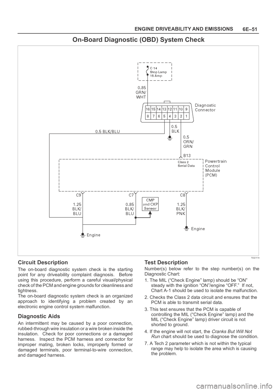
Circuit Description
The on-board diagnostic system check is the starting
point for any driveability complaint diagnosis. Before
using this procedure, perform a careful visual/physical
check of the PCM and engine grounds for cleanliness and
tightness.
The on-board diagnostic system check is an organized
approach to identifying a problem created by an
electronic engine control system malfunction.
Diagnostic Aids
An intermittent may be caused by a poor connection,
rubbed-through wire insulation or a wire broken inside the
insulation. Check for poor connections or a damaged
harness. Inspect the PCM harness and connector for
improper mating, broken locks, improperly formed or
damaged terminals, poor terminal-to-wire connection,
and damaged harness.
Test Description
Number(s) below refer to the step number(s) on the
Diagnostic Chart:
1. The MIL (“Check Engine” lamp) should be “ON”
steady with the ignition “ON”/engine “OFF.” If not,
Chart A-1 should be used to isolate the malfunction.
2. Checks the Class 2 data circuit and ensures that the
PCM is able to transmit serial data.
3. This test ensures that the PCM is capable of
controlling the MIL (“Check Engine” lamp) and the
MIL (“Check Engine” lamp) driver circuit is not
shorted to ground.
4. If the engine will not start, the
Cranks But Will Not
Run
chart should be used to diagnose the condition.
7. A Tech 2 parameter which is not within the typical
range may help to isolate the area which is causing
the problem.
Page 4711 of 6000
6E–54
ENGINE DRIVEABILITY AND EMISSIONS
A/C Clutch Control Circuit Diagnosis
D06RW085
Circuit Description
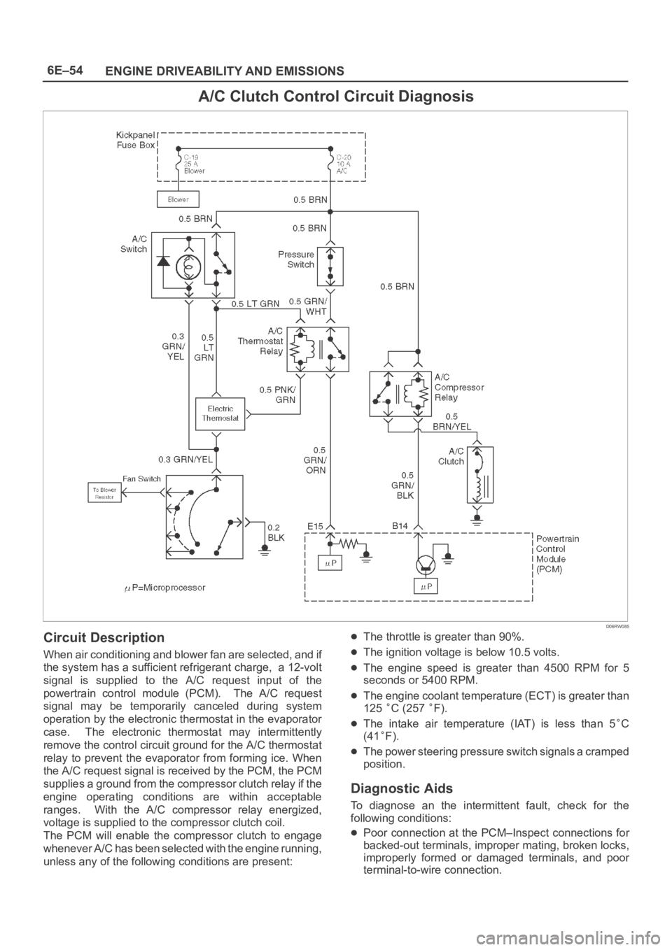
When air conditioning and blower fan are selected, and if
the system has a sufficient refrigerant charge, a 12-volt
signal is supplied to the A/C request input of the
powertrain control module (PCM). The A/C request
signal may be temporarily canceled during system
operation by the electronic thermostat in the evaporator
case. The electronic thermostat may intermittently
remove the control circuit ground for the A/C thermostat
relay to prevent the evaporator from forming ice. When
the A/C request signal is received by the PCM, the PCM
supplies a ground from the compressor clutch relay if the
engine operating conditions are within acceptable
ranges. With the A/C compressor relay energized,
voltage is supplied to the compressor clutch coil.
The PCM will enable the compressor clutch to engage
whenever A/C has been selected with the engine running,
unless any of the following conditions are present:
The throttle is greater than 90%.
The ignition voltage is below 10.5 volts.
The engine speed is greater than 4500 RPM for 5
seconds or 5400 RPM.
The engine coolant temperature (ECT) is greater than
125
C (257 F).
The intake air temperature (IAT) is less than 5C
(41
F).
The power steering pressure switch signals a cramped
position.
Diagnostic Aids
To diagnose an the intermittent fault, check for the
following conditions:
Poor connection at the PCM–Inspect connections for
backed-out terminals, improper mating, broken locks,
improperly formed or damaged terminals, and poor
terminal-to-wire connection.
Page 4723 of 6000
6E–66
ENGINE DRIVEABILITY AND EMISSIONS
Poor connection at PCM. Inspect the harness
connectors for backed-out terminals, improper mating,
broken locks, improperly formed or damage terminals,
and a poor terminal-to-wire connection.
Damaged harness. Inspect the wiring harness for
damage. If the harness is not damaged, observe an
affected sensor’s displayed value on the Tech 2 with
the ignition “ON” and the engine “OFF” while you move
the connectors and the wiring harnesses related to the
following sensors:
IAT
ECT
TP
MAP
EGR
TFT
Multiple PCM Information Sensor DTCs Set
StepActionVa l u e ( s )Ye sNo
1Was the “On-Board Diagnostic (OBD) System Check”
performed?
—Go to Step 2
Go to OBD
System
Check
21. Turn the ignition “OFF,” disconnect the PCM.
2. Turn the ignition “ON,” check the 5 volt reference A
circuit for the following conditions:
A poor connection at the PCM.
An open between the PCM connector and the
splice.
A short to ground.
A short to voltage.
Is there an open or short?
—Go to Step 3Go to Step 4
3Repair the open or short.
Is the action complete?
—Verify repair—
4Check the sensor ground circuit for the following
conditions:
A poor connection at the PCM or the affected
sensors.
An open between the PCM connector and the
affected sensors.
Is there an open or a poor connection?
—Go to Step 5Go to Step 6
5Repair the open or the poor connection.
Is the action complete?
—Verify repair—
6Measure the voltage between the EGR pintle position
sensor signal circuit at the PCM harness connector and
ground.
Does the voltage measure near the specified value?
0 VGo to Step 7Go to Step 12
7Measure the voltage between the MAP sensor signal
circuit at the PCM harness connector and ground.
Does the voltage measure near the specified value?
0 VGo to Step 8Go to Step 15
8Measure the voltage between the TP sensor signal
circuit at the PCM harness connector and ground.
Does the voltage measure near the specified value?
0 VGo to Step 9Go to Step 16
9Measure the voltage between the IAT sensor signal
circuit at the PCM harness connector and ground.
Does the voltage measure near the specified value?
0 VGo to Step 10Go to Step 17
10Measure the voltage between the ECT sensor signal
circuit at the PCM harness connector and ground.
Does the voltage measure near the specified value?
0 VGo to Step 11Go to Step 18
Page 4731 of 6000
6E–74
ENGINE DRIVEABILITY AND EMISSIONS
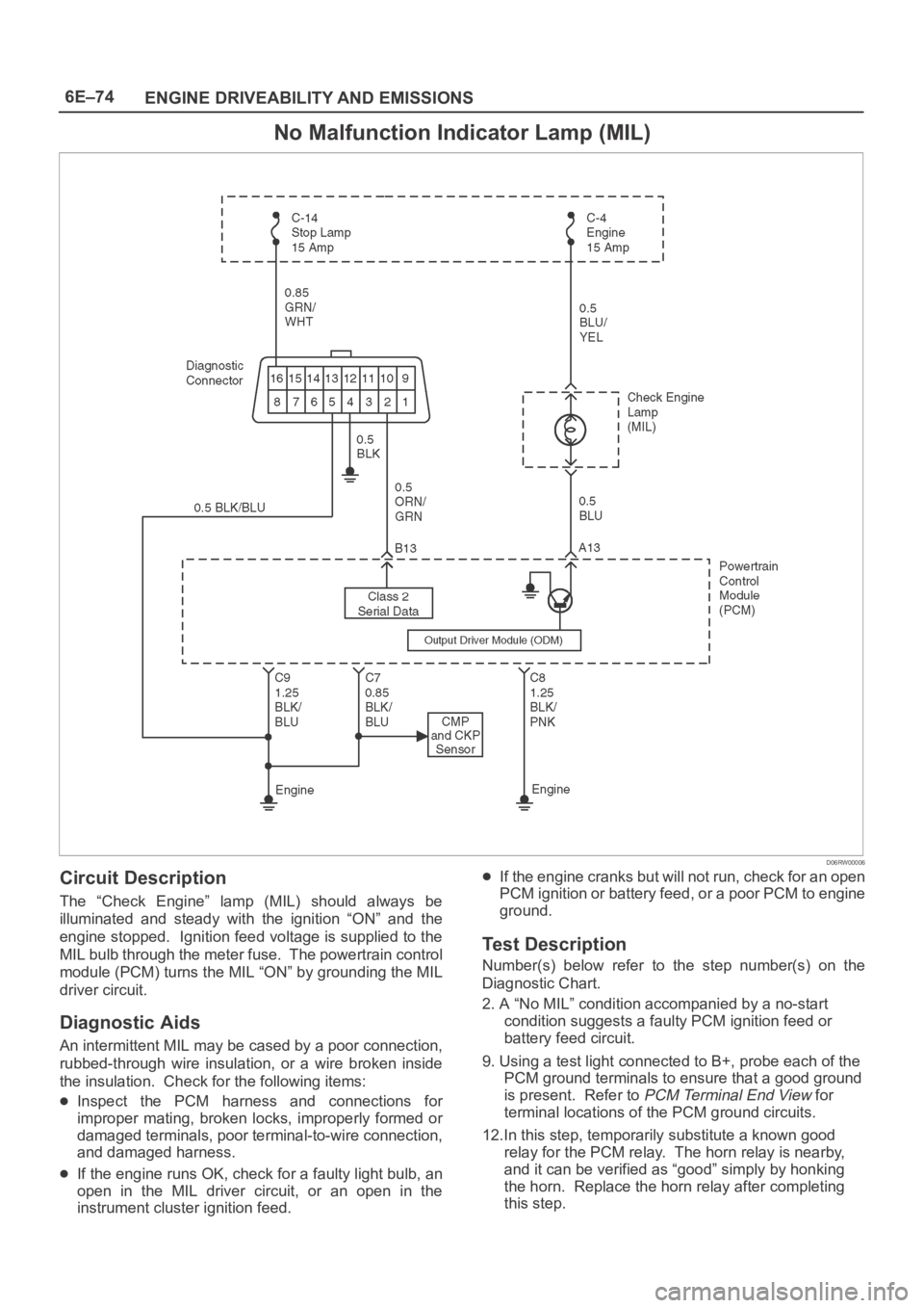
No Malfunction Indicator Lamp (MIL)
D06RW00006
Circuit Description
The “Check Engine” lamp (MIL) should always be
illuminated and steady with the ignition “ON” and the
engine stopped. Ignition feed voltage is supplied to the
MIL bulb through the meter fuse. The powertrain control
module (PCM) turns the MIL “ON” by grounding the MIL
driver circuit.
Diagnostic Aids
An intermittent MIL may be cased by a poor connection,
rubbed-through wire insulation, or a wire broken inside
the insulation. Check for the following items:
Inspect the PCM harness and connections for
improper mating, broken locks, improperly formed or
damaged terminals, poor terminal-to-wire connection,
and damaged harness.
If the engine runs OK, check for a faulty light bulb, an
open in the MIL driver circuit, or an open in the
instrument cluster ignition feed.
If the engine cranks but will not run, check for an open
PCM ignition or battery feed, or a poor PCM to engine
ground.
Test Description
Number(s) below refer to the step number(s) on the
Diagnostic Chart.
2. A “No MIL” condition accompanied by a no-start
condition suggests a faulty PCM ignition feed or
battery feed circuit.
9. Using a test light connected to B+, probe each of the
PCM ground terminals to ensure that a good ground
is present. Refer to
PCM Terminal End View for
terminal locations of the PCM ground circuits.
12.In this step, temporarily substitute a known good
relay for the PCM relay. The horn relay is nearby,
and it can be verified as “good” simply by honking
the horn. Replace the horn relay after completing
this step.