1998 OPEL FRONTERA check transmission fluid
[x] Cancel search: check transmission fluidPage 5847 of 6000

7A–66 AUTOMATIC TRANSMISSION (AW30-40LE)
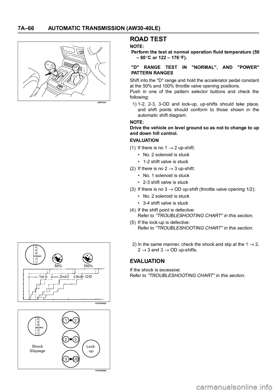
255RT004
F07RY00005
F07RY00006
ROAD TEST
NOTE:
Perform the test at normal operation fluid temperature (50
– 80
C or 122 – 176F).
"D" RANGE TEST IN "NORMAL", AND "POWER"
PATTERN RANGES
Shift into the "D" range and hold the accelerator pedal constant
at the 50% and 100% throttle valve opening positions.
Push in one of the pattern selector buttons and check the
fol lowing:
1) 1-2, 2-3, 3-OD and lock-up, up-shifts should take place,
and shift points should conform to those shown in the
automatic shift diagram.
NOTE:
Drive the vehicle on level ground so as not to change to up
and down hill control.
EVALUATION
(1) If there is no 1
2 up-shift:
• No. 2 solenoid is stuck
• 1-2 shift valve is stuck
(2) If there is no 2
3 up-shift:
• No. 1 solenoid is stuck
• 2-3 shift valve is stuck
(3) If there is no 3
OD up-shift (throttle valve opening 1/2):
• No. 2 solenoid is stuck
• 3-4 shift valve is stuck
(4) If the shift point is defective:
Refer to
"TROUBLESHOOTING CHART" in this section.
(5) If the lock-up is defective:
Refer to
"TROUBLESHOOTING CHART" in this section.
2) In the same manner, check the shock and slip at the 1 2,
2
3 and 3 OD up-shifts.
EVALUATION
If the shock is excessive:
Refer to
"TROUBLESHOOTING CHART" in this section.
Page 5856 of 6000

AUTOMATIC TRANSMISSION (AW30-40LE) 7A–75
ON-VEHICLE SERVICE
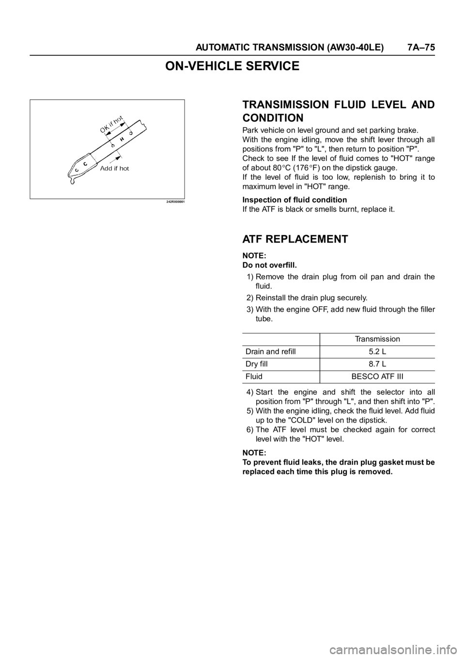
242RX00001
TRANSIMISSION FLUID LEVEL AND
CONDITION
Park vehicle on level ground and set parking brake.
With the engine idling, move the shift lever through all
positions from "P" to "L", then return to position "P".
Check to see If the level of fluid comes to "HOT" range
of about 80
C (176F) on the dipstick gauge.
If the level of fluid is too low, replenish to bring it to
maximum level in "HOT" range.
Inspection of fluid condition
If the ATF is black or smells burnt, replace it.
ATF REPLACEMENT
NOTE:
Do not overfill.
1) Remove the drain plug from oil pan and drain the
fluid.
2) Reinstall the drain plug securely.
3) With the engine OFF, add new fluid through the filler
tube.
4) Star t the engine and shift the selector into all
position from "P" through "L", and then shift into "P".
5) With the engine idling, check the fluid level. Add fluid
up to the "COLD" level on the dipstick.
6) The ATF level must be checked again for correct
level with the "HOT" level.
NOTE:
To prevent fluid leaks, the drain plug gasket must be
replaced each time this plug is removed.
Tr a n s m i s s i o n
Drain and refill 5.2 L
Dry fill 8.7 L
Fluid BESCO ATF III
Page 5888 of 6000

AUTOMATIC TRANSMISSION (AW30-40LE) 7A–107
DISASSEMBLY, INSPECTION AND
REASSEMBLY OF MINOR COMPONENTS
The instructions here are organized so that you work on only
one component group at a time.
This will help avoid confusion from similar-looking parts of
different subassemblies being on your workbench at the same
time.
The component groups are inspected and repaired from the
converter housing side.
As much as possible, complete the inspection, repair and
reassembly before proceeding to the next component group. If
a component group cannot be reassembled because parts are
being ordered, be sure to keep all parts of that group in a
separate container while proceeding with disassembly,
inspection, repair and reassembly of other component groups.
Recommended ATF type BESCO ATF II or III.
GENERAL CLEANING NOTES:
1. All disassembled parts should be washed clean and any
fluid passages and holes blown through with compressed
air.
2. When using compressed air to dry parts, always aim away
from yourself to prevent accidentally spraying automatic
transmission fluid in your face.
3. The recommended automatic transmission fluid should be
used for cleaning.
PARTS ARRANGEMENT:
1. After cleaning, the par ts should be arranged in proper order
to allow performing inspection, repairs, and reassembly
with efficiency.
2. When disassembling a valve body, be sure to keep each
valve together with the corresponding spring.
3. New brakes and clutches that are to be used for
replacement must be soaked in transmission fluid for at
least thir ty before assembly.
GENERAL ASSEMBLY:
1. All oil seal rings, clutch discs, clutch plates, rotating parts,
and sliding surfaces should be coated with transmission
fluid prior to reassembly.
2. All gaskets and rubber O-rings should be replaced.
3. Make sure that ends of a snap ring are not aligned with one
of the cutouts and are installed in the groove correctly.
4. If a worn bushing is to be replaced, the subassembly
containing that bushing must be replaced.
5.Check thrust bearings and races for wear or damage.
Replace if necessary.
6. Use petroleum jelly or vaseline to keep par ts in place.
Page 5994 of 6000

TRANSMISSION CONTROL SYSTEM (4L30–E)7A1–1
TRANSMISSION
TRANSMISSION CONTROL SYSTEM (4L30–E)
CONTENTS
Service Precaution 7A1–2. . . . . . . . . . . . . . . . . . . . . .
General Description 7A1–2. . . . . . . . . . . . . . . . . . . . .
Electronic Control Diagram 7A1–3. . . . . . . . . . . . .
Powertrain Control Module (PCM) 7A1–4. . . . . . .
Control System Diagram 7A1–5. . . . . . . . . . . . . . .
Shift Control 7A1–6. . . . . . . . . . . . . . . . . . . . . . . . . .
Band Apply Control 7A1–6. . . . . . . . . . . . . . . . . . . .
Torque Converter Clutch Control 7A1–6. . . . . . . . .
Line Pressure Control 7A1–6. . . . . . . . . . . . . . . . . .
On–Board Diagnostic System 7A1–6. . . . . . . . . . .
Fail Safe Mechanism 7A1–6. . . . . . . . . . . . . . . . . . .
Torque Management Control 7A1–6. . . . . . . . . . . .
ATF Warning Control 7A1–6. . . . . . . . . . . . . . . . . . .
ABS Control (If equipped) 7A1–6. . . . . . . . . . . . . .
Shift Mode Control 7A1–7. . . . . . . . . . . . . . . . . . . . .
Gear Shift Control 7A1–8. . . . . . . . . . . . . . . . . . . . .
Winter Drive Mode 7A1–9. . . . . . . . . . . . . . . . . . . . .
Backup Mode 7A1–9. . . . . . . . . . . . . . . . . . . . . . . . .
Functions of Input / Output Components 7A1–10. .
Diagnosis 7A1–11. . . . . . . . . . . . . . . . . . . . . . . . . . . . . .
Electronic Diagnosis 7A1–11. . . . . . . . . . . . . . . . . . .
Check Trans Indicator 7A1–11. . . . . . . . . . . . . . . . . .
Diagnostic Check 7A1–11. . . . . . . . . . . . . . . . . . . . . .
“Check Trans” Check 7A1–12. . . . . . . . . . . . . . . . . .
Tech2 OBD II Connection 7A1–13. . . . . . . . . . . . . . .
F0: Transmission Data 7A1–18. . . . . . . . . . . . . . . . .
F1: PC Solenoid Data 7A1–19. . . . . . . . . . . . . . . . . .
OBD II Diagnostic Management System 7A1–20. .
16 – Terminal Data Link Connector (DLC) 7A1–21.
Malfunction Indicator Lamp (MIL) 7A1–22. . . . . . . .
Types Of Diagnostic Trouble Codes (DTCs) 7A1–22
Clear DTC 7A1–22. . . . . . . . . . . . . . . . . . . . . . . . . . . .
DTC Check 7A1–23. . . . . . . . . . . . . . . . . . . . . . . . . . .
PCM Precaution 7A1–23. . . . . . . . . . . . . . . . . . . . . . .
Information On PCM 7A1–23. . . . . . . . . . . . . . . . . . .
Intermittent Conditions 7A1–23. . . . . . . . . . . . . . . . . Transmission And PCM Identification 7A1–24. . . . .
Isuzu Trooper 7A1–25. . . . . . . . . . . . . . . . . . . . . . . . .
Diagnostic Trouble Code (DTC)
Identification 7A1–26. . . . . . . . . . . . . . . . . . . . . . . . .
DTC P0218 Transmission Fluid Over
Temperature 7A1–27. . . . . . . . . . . . . . . . . . . . . . . . . . .
DTC P0560 System Voltage Malfunction 7A1–29. . .
DTC P0705 Transmission Range Switch
(Mode Switch) Illegal Position 7A1–32. . . . . . . . . . . .
DTC P0706 Transmission Range Switch
(Mode Switch) Performance 7A1–35. . . . . . . . . . . . . .
DTC P0712 Transmission Fluid Temperature
(TFT) Sensor Circuit Low Input 7A1–38. . . . . . . . . . .
DTC P0713 Transmission Fluid Temperature
(TFT) Sensor Circuit High Input 7A1–41. . . . . . . . . . .
DTC P0719 TCC Brake Switch Circuit High
(Stuck On) 7A1–44. . . . . . . . . . . . . . . . . . . . . . . . . . . . .
DTC P0722 Transmission Output Speed
Sensor (OSS) Low Input 7A1–47
. . . . . . . . . . . . . . . . .
DTC P0723 Transmission Output Speed
Sensor (OSS) Intermittent 7A1–50. . . . . . . . . . . . . . .
DTC P0730 Transmission Incorrect Gear
Ratio 7A1–53. . . . . . . . . . . . . . . . . . . . . . . . . . . . . . . . . .
DTC P0748 Pressure Control Solenoid
(PCS) (Force Motor) Circuit Electrical 7A1–56. . . . .
DTC P0753 Shift Solenoid A Electrical 7A1–58. . . . .
DTC P0758 Shift Solenoid B Electrical 7A1–61. . . . .
DTC P1790 ROM Transmission Side Bad
Check Sum 7A1–65. . . . . . . . . . . . . . . . . . . . . . . . . . . .
DTC P1792 EEPROM Transmission Side
Bad Check Sum 7A1–66. . . . . . . . . . . . . . . . . . . . . . . .
DTC P1835 Kickdown Switch Always On 7A1–67. . .
DTC P1850 Brake Band Apply Solenoid
Malfunction 7A1–69. . . . . . . . . . . . . . . . . . . . . . . . . . . .
DTC P1860 TCC Solenoid Electrical 7A1–73. . . . . . .
Transmission Fluid Temperature (TFT)
Sensor Specifications 7A1–76. . . . . . . . . . . . . . . . . . .