1998 OPEL FRONTERA check transmission fluid
[x] Cancel search: check transmission fluidPage 5699 of 6000
7A–10
AUTOMATIC TRANSMISSION (4L30–E)
Checking Transmission Fluid Level
and Condition
Checking fluid level and condition (color and odor) at
regular intervals will provide early diagnosis information
about the transmission. This information may be used to
correct a condition that, if not detected early, could result
in major transmission repairs.
IMPORTANT:When new, automatic transmission fluid
is red in color. As the vehicle is driven, the transmission
fluid will begin to look darker in color. The color may
eventually appear light brown.
A dark brown color with burnt odor may indicate
excessive fluid deterioration and signal a need for fluid
change.
Fluid Level
When adding or changing fluid, use only DEXRON –III.
Refer to Maintenance and Lubrication in General
Information section for maintenance information and
servicing interval.
CAUTION: DO NOT OVERFILL.
Overfilling will cause foaming, loss of fluid, abnor-
mal shifting and possible damage to the transmis-
sion.
1. Park the vehicle on level ground and apply the parking
brake firmly.
2. Check fluid level with engine running at idle.
NOTE: Be sure that transmission fluid temperature is
below 30
C (86F).
3. Move the selector lever through all gear ranges.
4. Move the selector lever to “Park”.
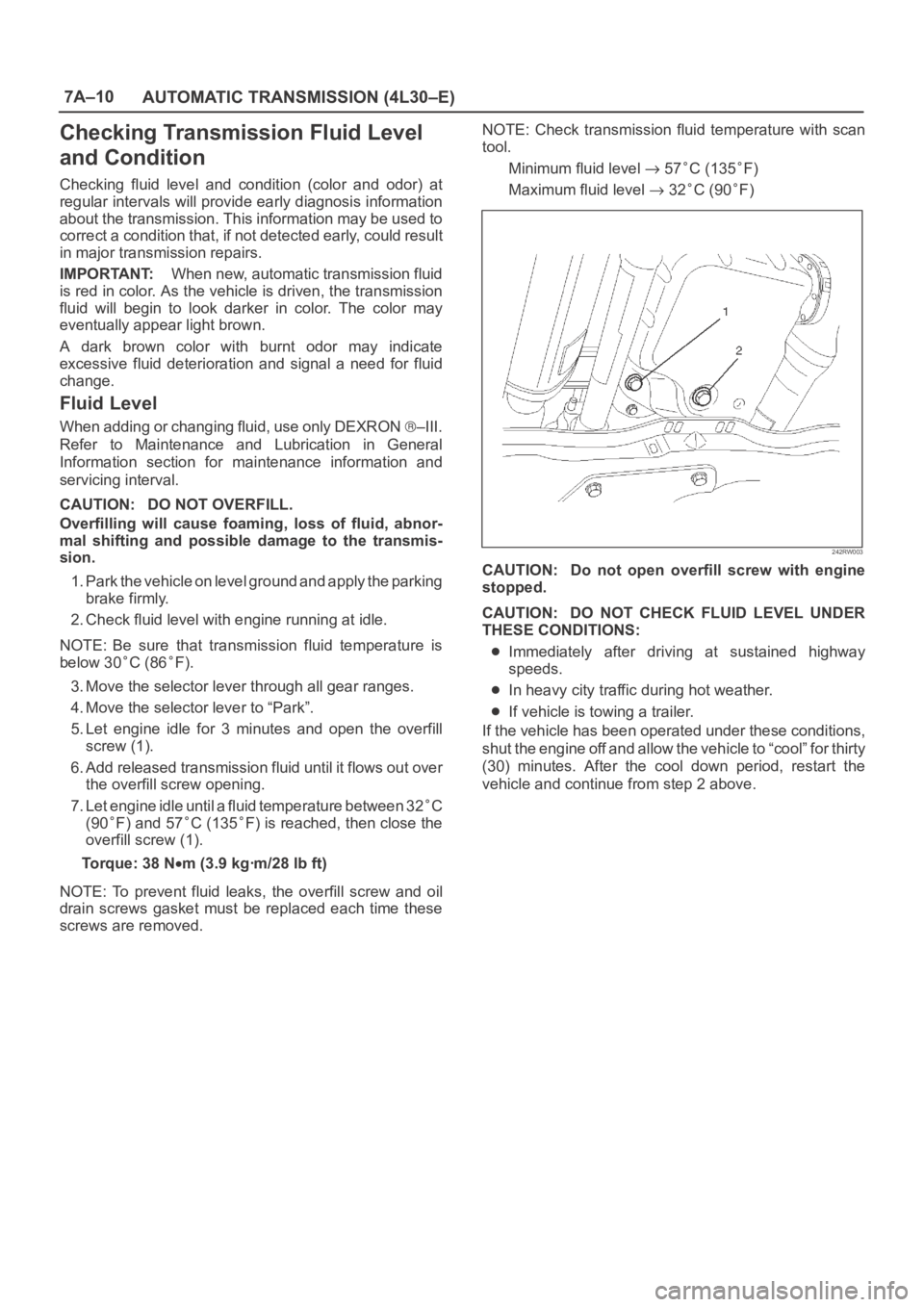
5. Let engine idle for 3 minutes and open the overfill
screw (1).
6. Add released transmission fluid until it flows out over
the overfill screw opening.
7. Let engine idle until a fluid temperature between 32
C
(90
F) and 57C (135F) is reached, then close the
overfill screw (1).
Torque: 38 N
m (3.9 kgꞏm/28 lb ft)
NOTE: To prevent fluid leaks, the overfill screw and oil
drain screws gasket must be replaced each time these
screws are removed.NOTE: Check transmission fluid temperature with scan
tool.
Minimum fluid level
57C (135F)
Maximum fluid level
32C (90F)
242RW003
CAUTION: Do not open overfill screw with engine
stopped.
CAUTION: DO NOT CHECK FLUID LEVEL UNDER
THESE CONDITIONS:
Immediately after driving at sustained highway
speeds.
In heavy city traffic during hot weather.
If vehicle is towing a trailer.
If the vehicle has been operated under these conditions,
shut the engine off and allow the vehicle to “cool” for thirty
(30) minutes. After the cool down period, restart the
vehicle and continue from step 2 above.
Page 5700 of 6000
7A–11 AUTOMATIC TRANSMISSION (4L30–E)
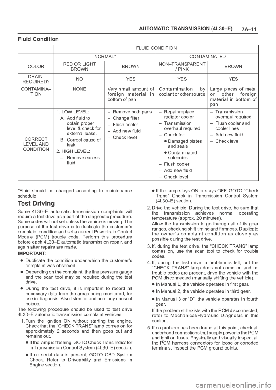
Fluid Condition
FLUID CONDITION
NORMAL*CONTAMINATED
COLORRED OR LIGHT
BROWNBROWNNON–TRANSPARENT
/ PINKBROWN
DRAIN
REQUIRED?NOYESYESYES
CONTAMINA–
TIONNONEVery small amount of
foreign material in
bottom of panContamination by
coolant or other sourceLarge pieces of metal
or other foreign
material in bottom of
pan
CORRECT
LEVEL AND
CONDITION
1. LOW LEVEL:
A. Add fluid to
obtain proper
level & check for
external leaks.
B. Correct cause of
leak.
2. HIGH LEVEL:
– Remove excess
fluid– Remove both pans
– Change filter
– Flush cooler
– Add new fluid
– Check level– Repair/replace
radiator cooler
–Transmission
overhaul required
– Check for:
Damaged plates
and seals
Contaminated
solenoids
– Flush cooler
– Add new fluid
– Check level
–Transmission
overhaul required
– Flush cooler and
cooler lines
– Add new fluid
– Check level
*Fluid should be changed according to maintenance
schedule.
Te s t D r i v i n g
Some 4L30–E automatic transmission complaints will
require a test drive as a part of the diagnostic procedure.
Some codes will not set unless the vehicle is moving. The
purpose of the test drive is to duplicate the customer’s
complaint condition and set a current Powertrain Control
Module (PCM) trouble code. Perform this procedure
before each 4L30–E automatic transmission repair, and
again after repairs are made.
IMPORTANT:
Duplicate the condition under which the customer’s
complaint was observed.
Depending on the complaint, the line pressure gauge
and the scan tool may be required during the test
drive.
During the test drive, it is important to record all
necessary data from the areas being monitored, for
use in diagnosis. Also listen for and note any unusual
noises.
The following procedure should be used to test drive
4L30–E automatic transmission complaint vehicles:
1. Turn the ignition ON without starting the engine.
Check that the “CHECK TRANS” lamp comes on for
approximately 2 seconds and then goes out and
remains out.
If the lamp is flashing, GOTO Check Trans Indicator
in Transmission Control System (4L30–E) section.
If no serial data is present, GOTO OBD System
Check. Refer to Driveability and Emissions in
Engine section.
If the lamp stays ON or stays OFF, GOTO “Check
Trans” Check in Transmission Control System
(4L30–E) section.
2. Drive the vehicle. During the test drive, be sure that
the transmission achieves normal operating
temperature (approx. 20 minutes).
Allow the transmission to go through all of its gear
ranges, checking shift timing and firmness. Duplicate
the owner’s complaint condition as closely as
possible during the test drive.
3. If, during the test drive, the “CHECK TRANS” lamp
comes on, use the scan tool to check for trouble
codes.
4. If, during the test drive, a problem is felt, but the
“CHECK TRANS” lamp does not come on and no
trouble codes are present, drive the vehicle with the
PCM disconnected (manually shifting the vehicle).
In Manual L, the vehicle operates in first gear.
In Manual 2, the vehicle operates in third gear.
In Manual 3 or “D”, the vehicle operates in fourth
gear.
If the problem still exists with the PCM disconnected,
refer to Mechanical/Hydraulic Diagnosis in this
section.
5. If no problem has been found at this point, check all
underhood connections that supply power to the PCM
and ignition fuses. Physically and visually inspect all
the PCM harness connectors for loose or corroded
terminals. Inspect the PCM ground points.
Page 5702 of 6000
7A–13 AUTOMATIC TRANSMISSION (4L30–E)
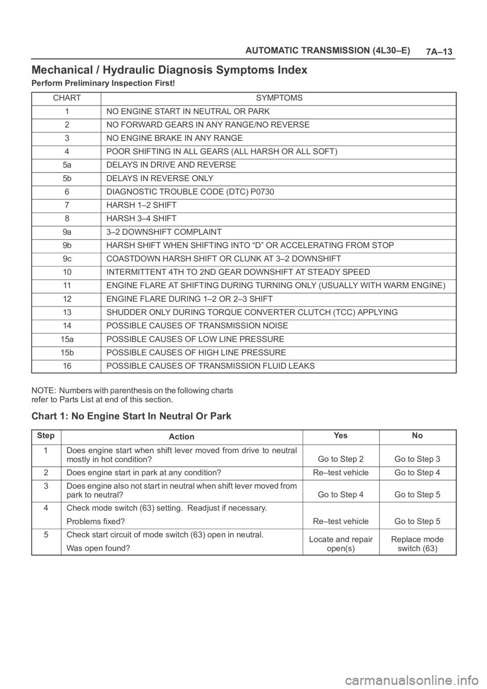
Mechanical / Hydraulic Diagnosis Symptoms Index
Perform Preliminary Inspection First!
CHART
SYMPTOMS
1NO ENGINE START IN NEUTRAL OR PARK
2NO FORWARD GEARS IN ANY RANGE/NO REVERSE
3NO ENGINE BRAKE IN ANY RANGE
4POOR SHIFTING IN ALL GEARS (ALL HARSH OR ALL SOFT)
5aDELAYS IN DRIVE AND REVERSE
5bDELAYS IN REVERSE ONLY
6DIAGNOSTIC TROUBLE CODE (DTC) P0730
7HARSH 1–2 SHIFT
8HARSH 3–4 SHIFT
9a3–2 DOWNSHIFT COMPLAINT
9bHARSH SHIFT WHEN SHIFTING INTO “D” OR ACCELERATING FROM STOP
9cCOASTDOWN HARSH SHIFT OR CLUNK AT 3–2 DOWNSHIFT
10INTERMITTENT 4TH TO 2ND GEAR DOWNSHIFT AT STEADY SPEED
11ENGINE FLARE AT SHIFTING DURING TURNING ONLY (USUALLY WITH WARM ENGINE)
12ENGINE FLARE DURING 1–2 OR 2–3 SHIFT
13SHUDDER ONLY DURING TORQUE CONVERTER CLUTCH (TCC) APPLYING
14POSSIBLE CAUSES OF TRANSMISSION NOISE
15aPOSSIBLE CAUSES OF LOW LINE PRESSURE
15bPOSSIBLE CAUSES OF HIGH LINE PRESSURE
16POSSIBLE CAUSES OF TRANSMISSION FLUID LEAKS
NOTE: Numbers with parenthesis on the following charts
refer to Parts List at end of this section.
Chart 1: No Engine Start In Neutral Or Park
StepActionYe sNo
1Does engine start when shift lever moved from drive to neutral
mostly in hot condition?
Go to Step 2Go to Step 3
2Does engine start in park at any condition?Re–test vehicleGo to Step 4
3Does engine also not start in neutral when shift lever moved from
park to neutral?
Go to Step 4Go to Step 5
4Check mode switch (63) setting. Readjust if necessary.
Problems fixed?
Re–test vehicleGo to Step 5
5Check start circuit of mode switch (63) open in neutral.
Was open found?Locate and repair
open(s)Replace mode
switch (63)
Page 5708 of 6000
7A–19 AUTOMATIC TRANSMISSION (4L30–E)
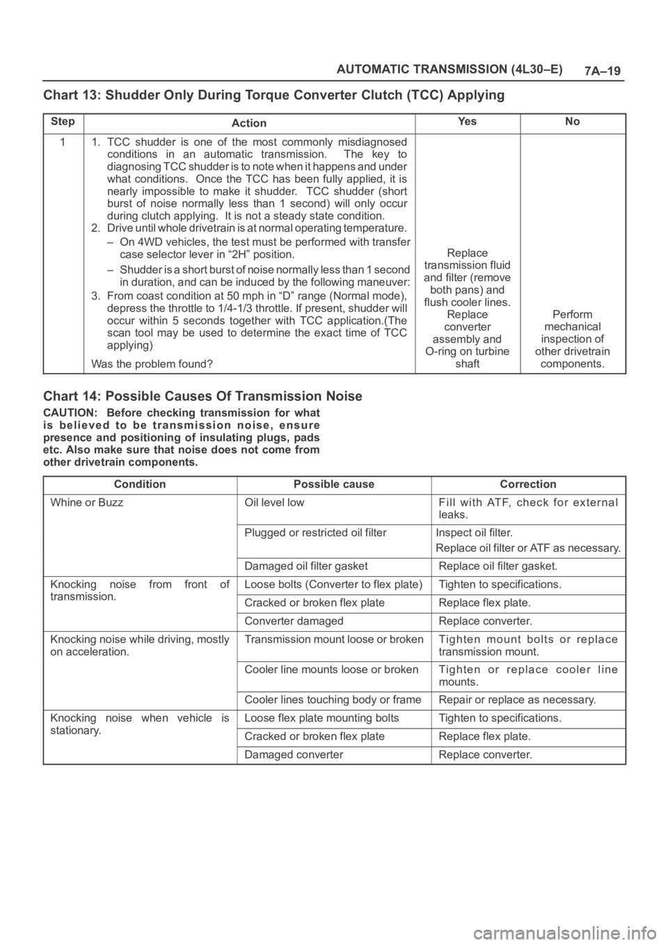
Chart 13: Shudder Only During Torque Converter Clutch (TCC) Applying
StepActionYe sNo
11. TCC shudder is one of the most commonly misdiagnosed
conditions in an automatic transmission. The key to
diagnosing TCC shudder is to note when it happens and under
what conditions. Once the TCC has been fully applied, it is
nearly impossible to make it shudder. TCC shudder (short
burst of noise normally less than 1 second) will only occur
during clutch applying. It is not a steady state condition.
2. Drive until whole drivetrain is at normal operating temperature.
– On 4WD vehicles, the test must be performed with transfer
case selector lever in “2H” position.
– Shudder is a short burst of noise normally less than 1 second
in duration, and can be induced by the following maneuver:
3. From coast condition at 50 mph in “D” range (Normal mode),
depress the throttle to 1/4-1/3 throttle. If present, shudder will
occur within 5 seconds together with TCC application.(The
scan tool may be used to determine the exact time of TCC
applying)
Was the problem found?
Replace
transmission fluid
and filter (remove
both pans) and
flush cooler lines.
Replace
converter
assembly and
O-ring on turbine
shaft
Perform
mechanical
inspection of
other drivetrain
components.
Chart 14: Possible Causes Of Transmission Noise
CAUTION: Before checking transmission for what
is believed to be transmission noise, ensure
presence and positioning of insulating plugs, pads
etc. Also make sure that noise does not come from
other drivetrain components.
Condition
Possible causeCorrection
Whine or BuzzOil level lowFill with ATF, check for external
leaks.
Plugged or restricted oil filterInspect oil filter.
Replace oil filter or ATF as necessary.
Damaged oil filter gasketReplace oil filter gasket.
Knocking noise from front of
transmission
Loose bolts (Converter to flex plate)Tighten to specifications.
transmission.Cracked or broken flex plateReplace flex plate.
Converter damagedReplace converter.
Knocking noise while driving, mostly
on acceleration.Transmission mount loose or brokenTighten mount bolts or replace
transmission mount.
Cooler line mounts loose or brokenTighten or replace cooler line
mounts.
Cooler lines touching body or frameRepair or replace as necessary.
Knocking noise when vehicle is
stationary
Loose flex plate mounting boltsTighten to specifications.
stationary.Cracked or broken flex plateReplace flex plate.
Damaged converterReplace converter.
Page 5711 of 6000
7A–22
AUTOMATIC TRANSMISSION (4L30–E)
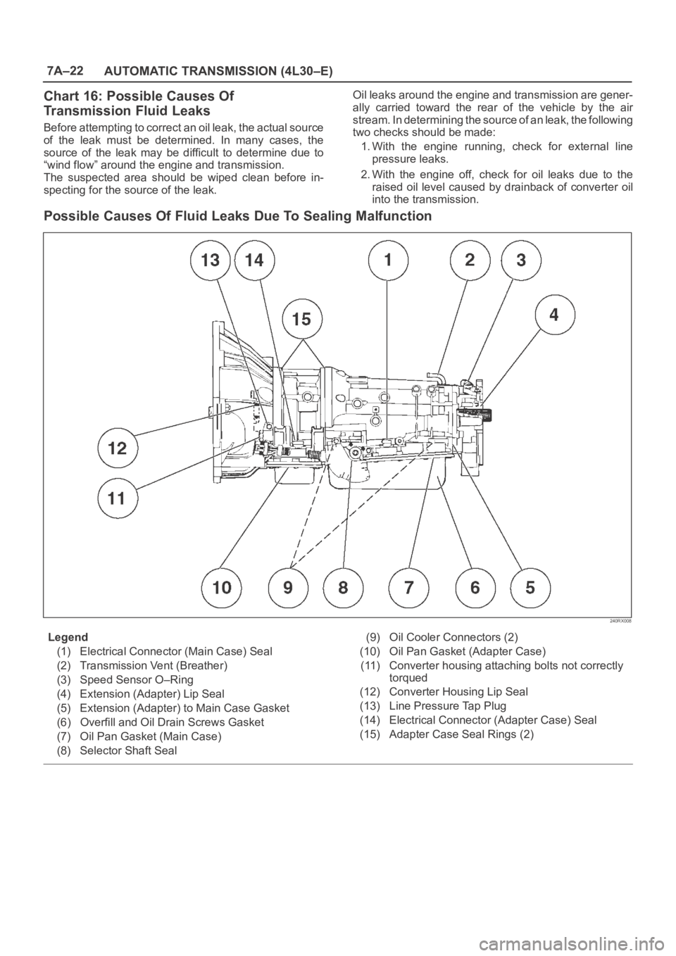
Chart 16: Possible Causes Of
Transmission Fluid Leaks
Before attempting to correct an oil leak, the actual source
of the leak must be determined. In many cases, the
source of the leak may be difficult to determine due to
“wind flow” around the engine and transmission.
The suspected area should be wiped clean before in-
specting for the source of the leak.Oil leaks around the engine and transmission are gener-
ally carried toward the rear of the vehicle by the air
stream. In determining the source of an leak, the following
two checks should be made:
1. With the engine running, check for external line
pressure leaks.
2. With the engine off, check for oil leaks due to the
raised oil level caused by drainback of converter oil
into the transmission.
Possible Causes Of Fluid Leaks Due To Sealing Malfunction
240RX008
Legend
(1) Electrical Connector (Main Case) Seal
(2) Transmission Vent (Breather)
(3) Speed Sensor O–Ring
(4) Extension (Adapter) Lip Seal
(5) Extension (Adapter) to Main Case Gasket
(6) Overfill and Oil Drain Screws Gasket
(7) Oil Pan Gasket (Main Case)
(8) Selector Shaft Seal(9) Oil Cooler Connectors (2)
(10) Oil Pan Gasket (Adapter Case)
(11) Converter housing attaching bolts not correctly
torqued
(12) Converter Housing Lip Seal
(13) Line Pressure Tap Plug
(14) Electrical Connector (Adapter Case) Seal
(15) Adapter Case Seal Rings (2)
Page 5712 of 6000
7A–23 AUTOMATIC TRANSMISSION (4L30–E)
Stall Test
The stall test allows you to check the transmission for
internal abrasion and the one way clutch for slippage.
Torque converter performance can also be evaluated.
The stall test results together with the road test results will
identify transmission components requiring servicing or
adjustment.
Stall Test Procedure:
1. Check the level of the engine coolant, the engine oil,
and the automatic transmission fluid. Replenish if
necessary.
2. Block the wheels and set the parking brake.
3. Connect a tachometer to the engine.
4. Start the engine and allow it to idle until the engine
coolant temperature reaches 70 – 80
C (158 –
176
F).
5. Hold the brake pedal down as far as it will go.
6. Place the selector in the “D” range.
7. Gradually push the accelerator pedal to the floor.
The throttle valve will be fully open.
Note the engine speed at which the tachometer
needle stabilizes.
Stall Speed : 2,100
150 rpm
NOTE: Do not continuously run this test longer than 5
seconds.
8. Release the accelerator pedal.
9. Place the selector in the “N” range.
10. Run the engine at 1,200 rpm for one minute.
This will cool the transmission fluid.
11. Repeat Steps 7 – 10 for the “3”, “2”, “L” and “R”
ranges.
Line Pressure Test
The line pressure test checks oil pump and control valve
pressure regulator valve function. It will also detect oil
leakage.
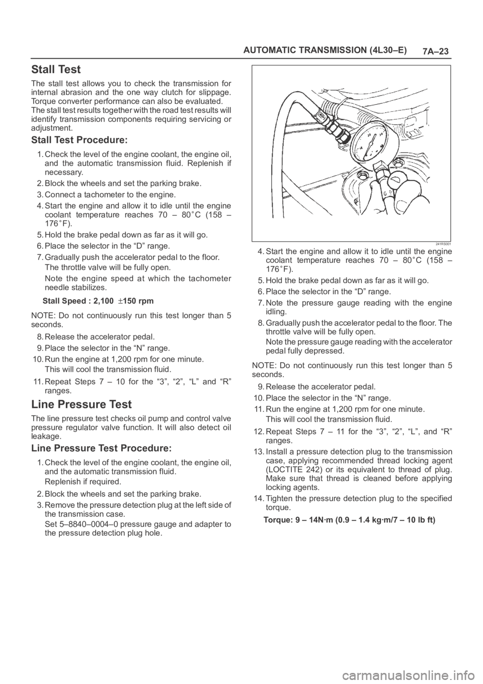
Line Pressure Test Procedure:
1. Check the level of the engine coolant, the engine oil,
and the automatic transmission fluid.
Replenish if required.
2. Block the wheels and set the parking brake.
3. Remove the pressure detection plug at the left side of
the transmission case.
Set 5–8840–0004–0 pressure gauge and adapter to
the pressure detection plug hole.
241RS001
4. Start the engine and allow it to idle until the engine
coolant temperature reaches 70 – 80
C (158 –
176
F).
5. Hold the brake pedal down as far as it will go.
6. Place the selector in the “D” range.
7. Note the pressure gauge reading with the engine
idling.
8. Gradually push the accelerator pedal to the floor. The
throttle valve will be fully open.
Note the pressure gauge reading with the accelerator
pedal fully depressed.
NOTE: Do not continuously run this test longer than 5
seconds.
9. Release the accelerator pedal.
10. Place the selector in the “N” range.
11. Run the engine at 1,200 rpm for one minute.
This will cool the transmission fluid.
12. Repeat Steps 7 – 11 for the “3”, “2”, “L”, and “R”
ranges.
13. Install a pressure detection plug to the transmission
case, applying recommended thread locking agent
(LOCTITE 242) or its equivalent to thread of plug.
Make sure that thread is cleaned before applying
locking agents.
14. Tighten the pressure detection plug to the specified
torque.
Torque:9–14Nꞏm(0.9–1.4kgꞏm/7–10lbft)
Page 5718 of 6000
7A–29 AUTOMATIC TRANSMISSION (4L30–E)
Changing Transmission Fluid
There is no need to change the transmission fluid unless
the transmission is used under one or more of the
following heavy duty conditions.
A. Repeated short trips
B. Driving on rough roads
C. Driving on dusty roads
D. Towing a trailer
If the vehicle is used under these conditions, change the
fluid every 20,000 miles (32,000 km).
More over, the remaining life percentage of ATF can be
estimated by using Tech 2 as an auxiliary tool to judge the
right time for ATF replacement.
The remaining life percentage is calculated from ATF’S
heat history. When it is close to 0%, ATF replacement is
recommended.
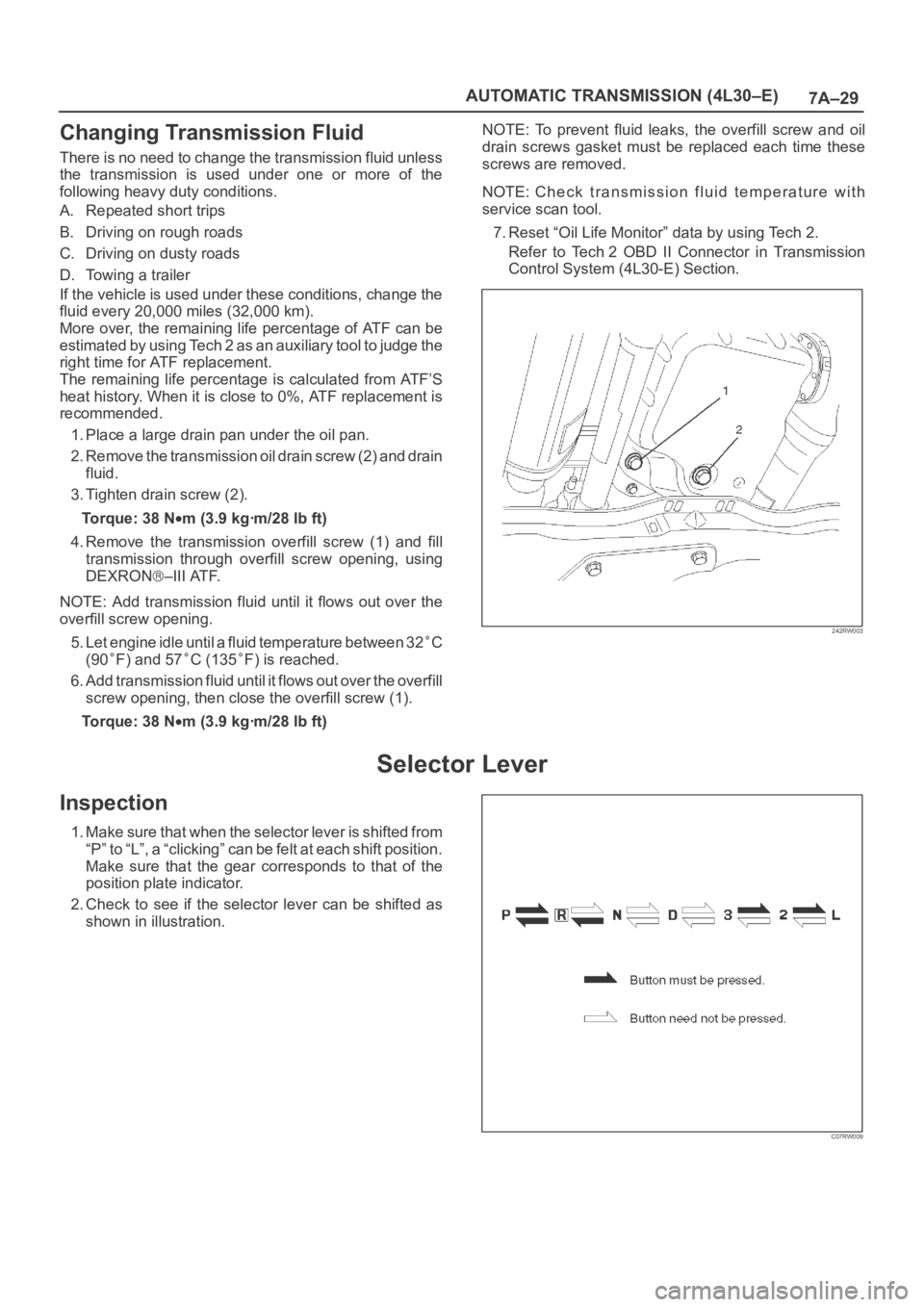
1. Place a large drain pan under the oil pan.
2. Remove the transmission oil drain screw (2) and drain
fluid.
3. Tighten drain screw (2).
Torque: 38 N
m (3.9 kgꞏm/28 lb ft)
4. Remove the transmission overfill screw (1) and fill
transmission through overfill screw opening, using
DEXRON
–III ATF.
NOTE: Add transmission fluid until it flows out over the
overfill screw opening.
5. Let engine idle until a fluid temperature between 32
C
(90
F) and 57C (135F) is reached.
6. Add transmission fluid until it flows out over the overfill
screw opening, then close the overfill screw (1).
Torque: 38 N
m (3.9 kgꞏm/28 lb ft)NOTE: To prevent fluid leaks, the overfill screw and oil
drain screws gasket must be replaced each time these
screws are removed.
NOTE: Check transmission fluid temperature with
service scan tool.
7. Reset “Oil Life Monitor” data by using Tech 2.
Refer to Tech 2 OBD II Connector in Transmission
Control System (4L30-E) Section.
242RW003
Selector Lever
Inspection
1. Make sure that when the selector lever is shifted from
“P” to “L”, a “clicking” can be felt at each shift position.
Make sure that the gear corresponds to that of the
position plate indicator.
2. Check to see if the selector lever can be shifted as
shown in illustration.
C07RW009
Page 5730 of 6000
7A–41 AUTOMATIC TRANSMISSION (4L30–E)
Valve Body Assembly (Main Case)
Removal
1. Raise the vehicle and support it on jack stands.
2. Disconnect battery ground cable.
3. Remove transfer and exhaust protectors.
4. Drain fluid.
5. Remove exhaust pipe and disconnect oxygen sensor
connector.
6. Support transfer case with a jack and remove third
crossmember.
7. Remove sixteen 10 mm screws, main case oil pan,
magnet and gasket.
8. Remove three 13 mm oil filter fixing screws, then
remove oil filter.
9. Remove two 13 mm manual detent fixing screws,
then remove roller and spring assembly.
10. Disconnect wiring harness from band control
solenoid and shift solenoids. Pull only on connectors,
not on wiring harness.
11. Remove four 13 mm servo cover fixing screws, then
remove servo cover and gasket.
12. Remove seven 13 mm valve body fixing screws.
Disconnect the ground wire from the main case
valve body.
13. Remove main case valve body with manual valve link
and transfer plate. Note the position of the link (long
end into valve, short end into range selector lever).
14. Remove transfer plate gasket from main case.
15. Remove two check balls from main case.
Installation
1. Install two check balls to main case.
244RW002
2. Inspect electrical 4 pin connector and seal of main
case. Replace if necessary.3. Use two 5–8840–0022–0 (J–25025–B) guide pin to
install main case.
Install valve body assembly and manual valve link.
NOTE: Valve must be extended as the short end of
manual valve link is connected to the range selector lever.
Long end of link goes into valve.
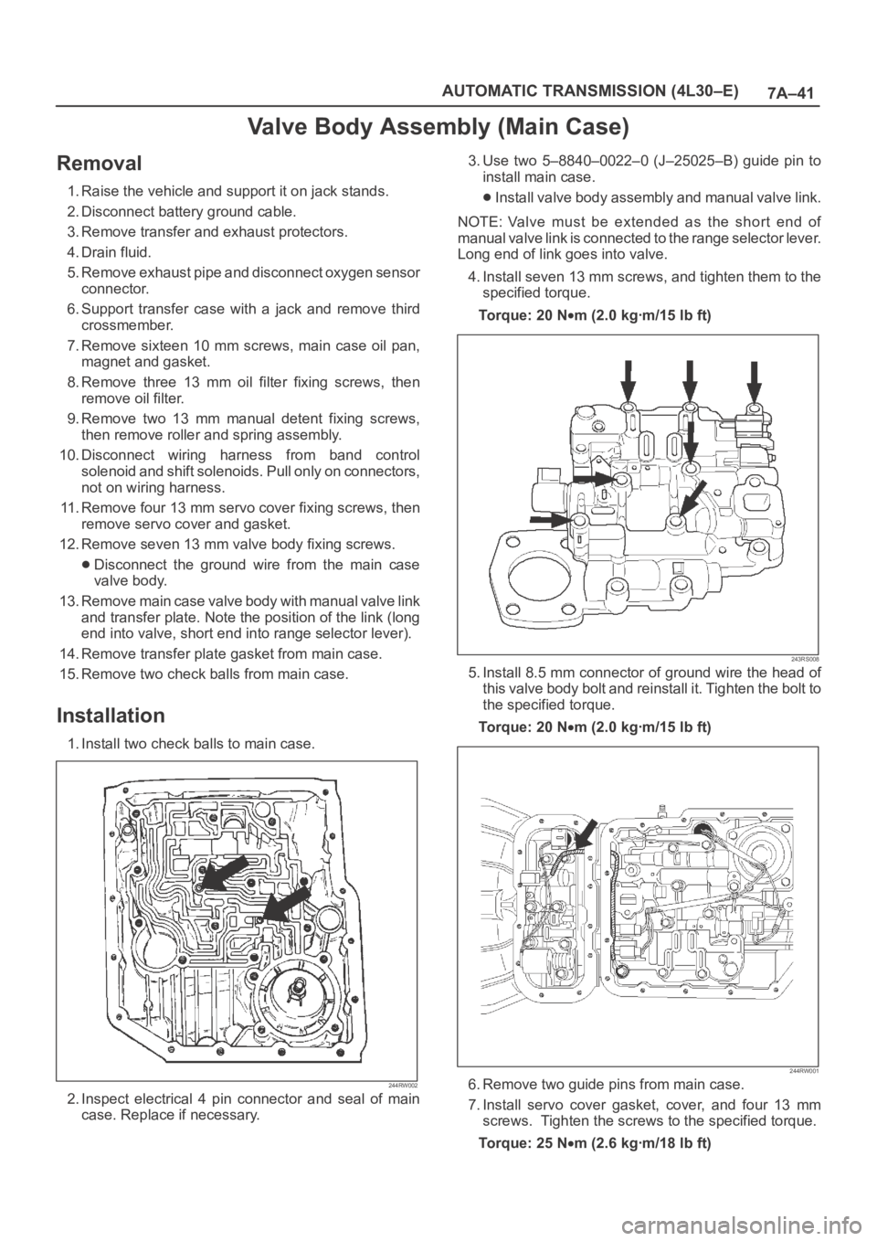
4. Install seven 13 mm screws, and tighten them to the
specified torque.
To r q u e : 2 0 N
m (2.0 kgꞏm/15 lb ft)
243RS008
5. Install 8.5 mm connector of ground wire the head of
this valve body bolt and reinstall it. Tighten the bolt to
the specified torque.
To r q u e : 2 0 N
m (2.0 kgꞏm/15 lb ft)
244RW001
6. Remove two guide pins from main case.
7. Install servo cover gasket, cover, and four 13 mm
screws. Tighten the screws to the specified torque.
To r q u e : 2 5 N
m (2.6 kgꞏm/18 lb ft)