1998 OPEL FRONTERA check engine light
[x] Cancel search: check engine lightPage 1832 of 6000
ENGINE MECHANICAL 6A – 99
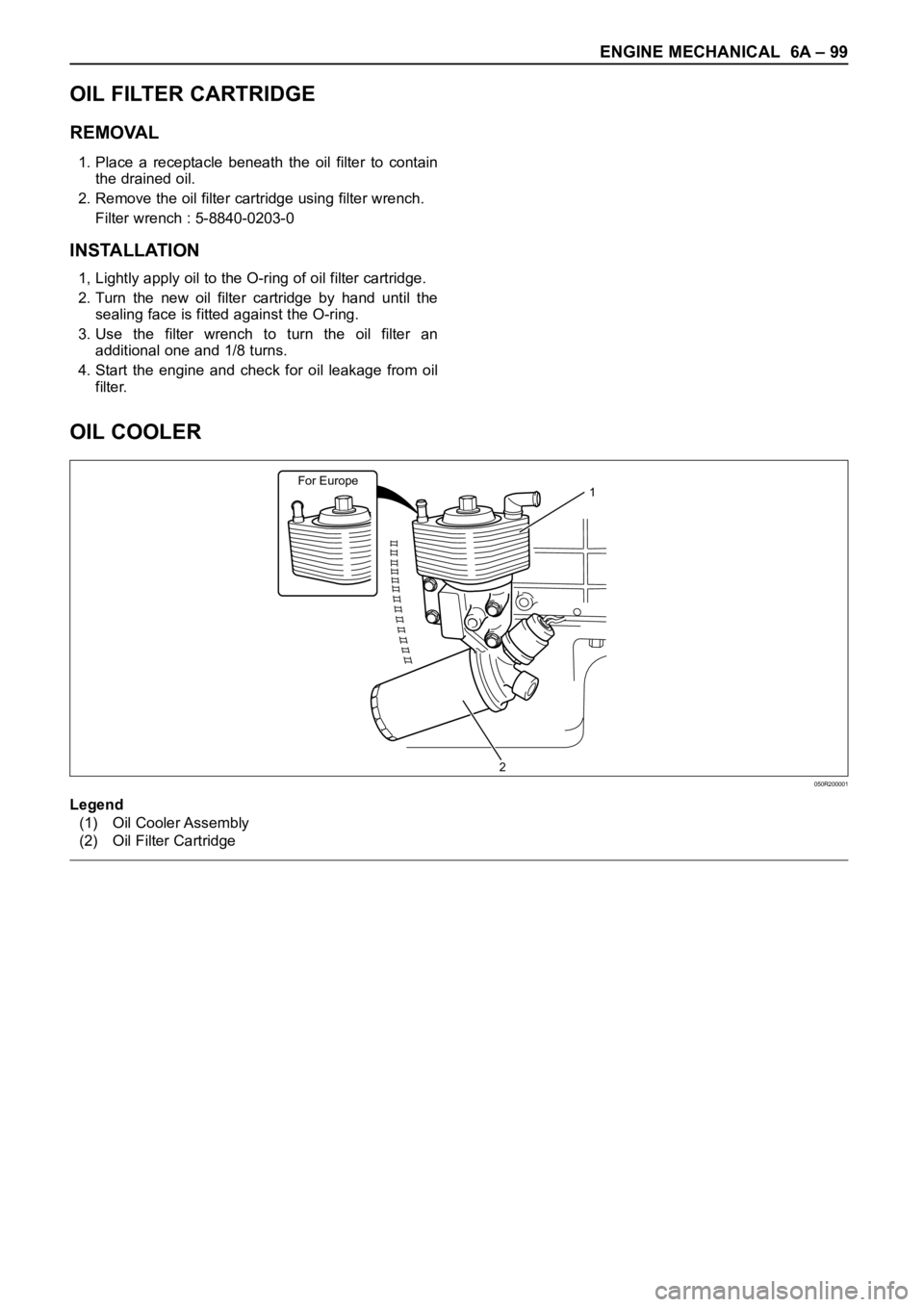
OIL COOLER
For Europe1
2050R200001
Legend
(1) Oil Cooler Assembly
(2) Oil Filter Cartridge
OIL FILTER CARTRIDGE
REMOVAL
1. Place a receptacle beneath the oil filter to contain
the drained oil.
2. Remove the oil filter cartridge using filter wrench.
Filter wrench : 5-8840-0203-0
INSTALLATION
1, Lightly apply oil to the O-ring of oil filter cartridge.
2. Turn the new oil filter cartridge by hand until the
sealing face is fitted against the O-ring.
3. Use the filter wrench to turn the oil filter an
additional one and 1/8 turns.
4. Start the engine and check for oil leakage from oil
filter.
Page 1868 of 6000

ENGINE ELECTRICAL 6D – 1
ENGINE ELECTRICAL
CONTENTS
Battery . . . . . . . . . . . . . . . . . . . . . . . . . . . . 6D–1
General Description . . . . . . . . . . . . . . . . 6D–1
Diagnosis . . . . . . . . . . . . . . . . . . . . . . . . 6D–1
On Vehicle Service . . . . . . . . . . . . . . . . . 6D–3
Main Data and Specification . . . . . . . . . . 6D–4
Starting System . . . . . . . . . . . . . . . . . . . . . 6D–5
General Description . . . . . . . . . . . . . . . . 6D–5
On Vehicle Service . . . . . . . . . . . . . . . . . 6D–7
Starter . . . . . . . . . . . . . . . . . . . . . . . . . . 6D–7
Unit Repair . . . . . . . . . . . . . . . . . . . . . . . 6D–8Charging System . . . . . . . . . . . . . . . . . . . . 6D–15
General Description . . . . . . . . . . . . . . . . 6D–15
Diagnosis . . . . . . . . . . . . . . . . . . . . . . . . 6D–16
Unit Repair . . . . . . . . . . . . . . . . . . . . . . . 6D–17
Main Data and Specification . . . . . . . . . . 6D–22
QOS4 Preheating System . . . . . . . . . . . . . . 6D–23
General Description . . . . . . . . . . . . . . . . 6D–23
System Diagram . . . . . . . . . . . . . . . . . . . 6D–23
Inspection of QOS4 System Operation . . 6D–24
BATTERY
GENERAL DESCRIPTION
DIAGNOSIS
There are six battery fluid caps at the top of the battery.
These are covered by a paper label.
The battery is completely sealed except for the six
small vent holes at the side. These vent holes permit
the escape of small amounts of gas generated by the
battery.
This type of battery has the following advantages over
conventional batteries:1. There is no need to add water during the entire
service life of the battery.
2. The battery protects itself against overcharging.
The battery will refuse to accept an excessive
charge.
(A conventional battery will accept an excessive
charge, resulting in gassing and loss of battery
fluid.)
3. The battery is much less vulnerable to self-
discharge than a conventional type battery.
1. VISUAL INSPECTION (Step 1)
Inspect the battery for obvious physical damage, such
as a cracked or broken case, which would permit
electrolyte loss.
Replace the battery if obvious physical damage is
discovered during inspection.
Check for any other physical damage and correct it as
necessary. If not, proceed to Step 2.
2. HYDROMETER CHECK (Step 2)
There is a built-in hydrometer (Charge test indicator) at
the top of the battery. It is designed to be used during
diagnostic procedures.
Before trying to read the hydrometer, carefully clean the
upper battery surface.
If your work area is poorly lit, additional light may be
necessary to read the hydrometer.
a. BLUE RING OR DOT VISIBLE – Go to Step 4.
b. BLUE RING OR DOT NOT VISIBLE – Go to
Step 3.3. FLUID LEVEL CHECK (Step 3)
The fluid level should be between the upper level line
and lower level line on side of the battery.
a. CORRECT FLUID LEVEL – Charge the battery.
b. BELOW LOWER LEVEL – Replace battery.
4. VOLTAGE CHECK (Step 4)
(1) Put voltmeter test leads to battery terminals.
a. VOLTAGE IS 12.4V OR ABOVE – Go to Step 5.
b. VOLTAGE IS UNDER 12.4V – Go to procedure
(2) below.
(2) Determine fast charge amperage from
specification. (See Main Data and Specifications in
this section.)
Fast charge battery for 30 minutes at amperage
rate no higher than specified value.
Take voltage and amperage readings after charge.
a. VOLTAGE IS ABOVE 16V AT BELOW 1/3 OF
AMPERAGE RATE – Replace battery.
Page 1924 of 6000
6E–31 4JX1–TC ENGINE DRIVEABILITY AND EMISSIONS
060RW120
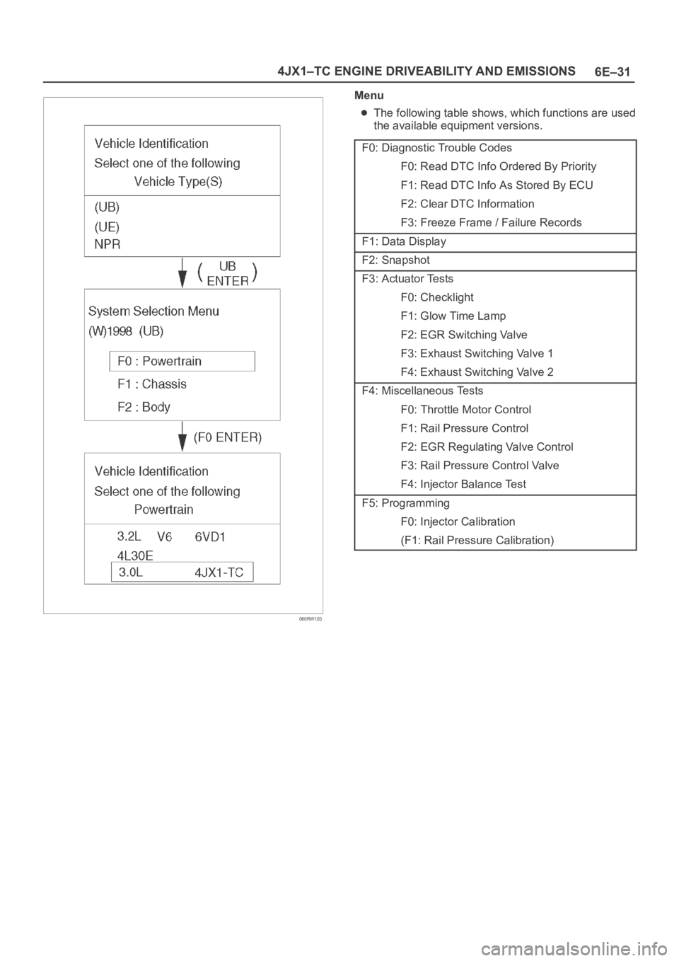
Menu
The following table shows, which functions are used
the available equipment versions.
F0: Diagnostic Trouble Codes
F0: Read DTC Info Ordered By Priority
F1: Read DTC Info As Stored By ECU
F2: Clear DTC Information
F3: Freeze Frame / Failure Records
F1: Data Display
F2: Snapshot
F3: Actuator Tests
F0: Checklight
F1: Glow Time Lamp
F2: EGR Switching Valve
F3: Exhaust Switching Valve 1
F4: Exhaust Switching Valve 2
F4: Miscellaneous Tests
F0: Throttle Motor Control
F1: Rail Pressure Control
F2: EGR Regulating Valve Control
F3: Rail Pressure Control Valve
F4: Injector Balance Test
F5: Programming
F0: Injector Calibration
(F1: Rail Pressure Calibration)
Page 1937 of 6000
6E–44
4JX1–TC ENGINE DRIVEABILITY AND EMISSIONS
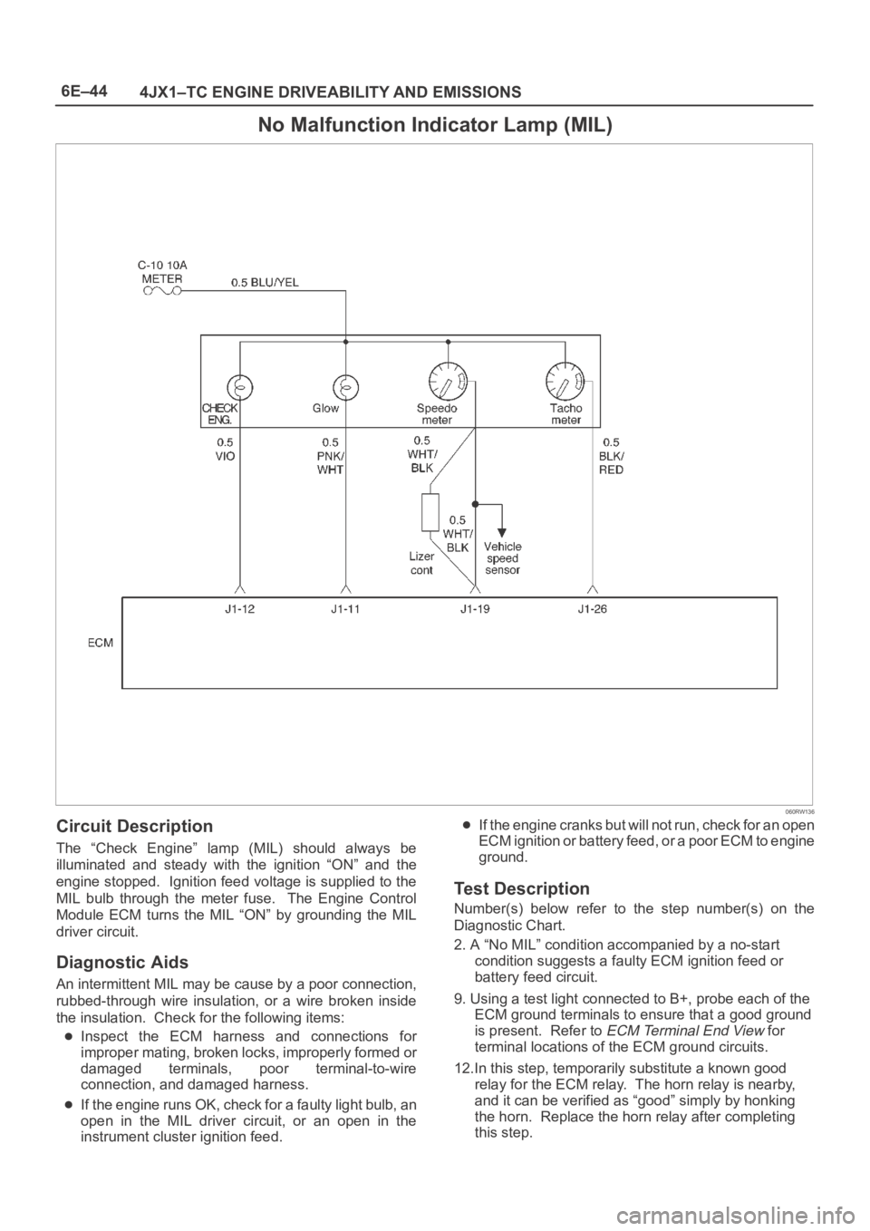
No Malfunction Indicator Lamp (MIL)
060RW136
Circuit Description
The “Check Engine” lamp (MIL) should always be
illuminated and steady with the ignition “ON” and the
engine stopped. Ignition feed voltage is supplied to the
MIL bulb through the meter fuse. The Engine Control
Module ECM turns the MIL “ON” by grounding the MIL
driver circuit.
Diagnostic Aids
An intermittent MIL may be cause by a poor connection,
rubbed-through wire insulation, or a wire broken inside
the insulation. Check for the following items:
Inspect the ECM harness and connections for
improper mating, broken locks, improperly formed or
damaged terminals, poor terminal-to-wire
connection, and damaged harness.
If the engine runs OK, check for a faulty light bulb, an
open in the MIL driver circuit, or an open in the
instrument cluster ignition feed.
If the engine cranks but will not run, check for an open
ECM ignition or battery feed, or a poor ECM to engine
ground.
Test Description
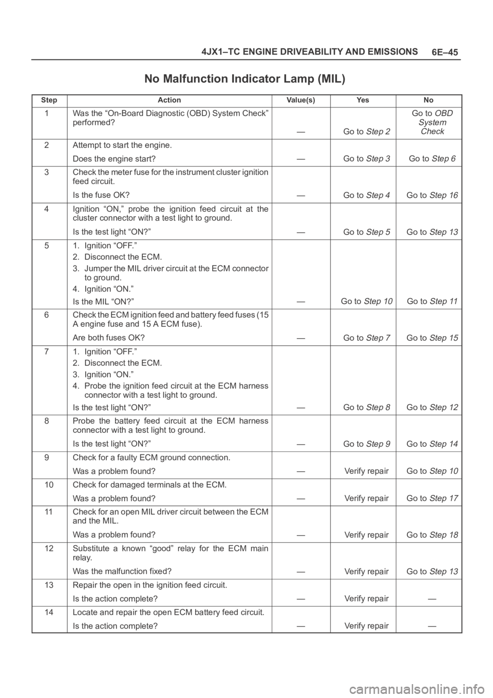
Number(s) below refer to the step number(s) on the
Diagnostic Chart.
2. A “No MIL” condition accompanied by a no-start
condition suggests a faulty ECM ignition feed or
battery feed circuit.
9. Using a test light connected to B+, probe each of the
ECM ground terminals to ensure that a good ground
is present. Refer to
ECM Terminal End View for
terminal locations of the ECM ground circuits.
12.In this step, temporarily substitute a known good
relay for the ECM relay. The horn relay is nearby,
and it can be verified as “good” simply by honking
the horn. Replace the horn relay after completing
this step.
Page 1938 of 6000
6E–45 4JX1–TC ENGINE DRIVEABILITY AND EMISSIONS
No Malfunction Indicator Lamp (MIL)
StepActionVa l u e ( s )Ye sNo
1Was the “On-Board Diagnostic (OBD) System Check”
performed?
—Go to Step 2
Go to OBD
System
Check
2Attempt to start the engine.
Does the engine start?
—Go to Step 3Go to Step 6
3Check the meter fuse for the instrument cluster ignition
feed circuit.
Is the fuse OK?
—Go to Step 4Go to Step 16
4Ignition “ON,” probe the ignition feed circuit at the
cluster connector with a test light to ground.
Is the test light “ON?”
—Go to Step 5Go to Step 13
51. Ignition “OFF.”
2. Disconnect the ECM.
3. Jumper the MIL driver circuit at the ECM connector
to ground.
4. Ignition “ON.”
Is the MIL “ON?”
—Go to Step 10Go to Step 11
6Check the ECM ignition feed and battery feed fuses (15
A engine fuse and 15 A ECM fuse).
Are both fuses OK?
—Go to Step 7Go to Step 15
71. Ignition “OFF.”
2. Disconnect the ECM.
3. Ignition “ON.”
4. Probe the ignition feed circuit at the ECM harness
connector with a test light to ground.
Is the test light “ON?”
—Go to Step 8Go to Step 12
8Probe the battery feed circuit at the ECM harness
connector with a test light to ground.
Is the test light “ON?”
—Go to Step 9Go to Step 14
9Check for a faulty ECM ground connection.
Was a problem found?
—Verify repairGo to Step 10
10Check for damaged terminals at the ECM.
Was a problem found?
—Verify repairGo to Step 17
11Check for an open MIL driver circuit between the ECM
and the MIL.
Was a problem found?
—Verify repairGo to Step 18
12Substitute a known “good” relay for the ECM main
relay.
Was the malfunction fixed?
—Verify repairGo to Step 13
13Repair the open in the ignition feed circuit.
Is the action complete?
—Verify repair—
14Locate and repair the open ECM battery feed circuit.
Is the action complete?
—Verify repair—
Page 1943 of 6000
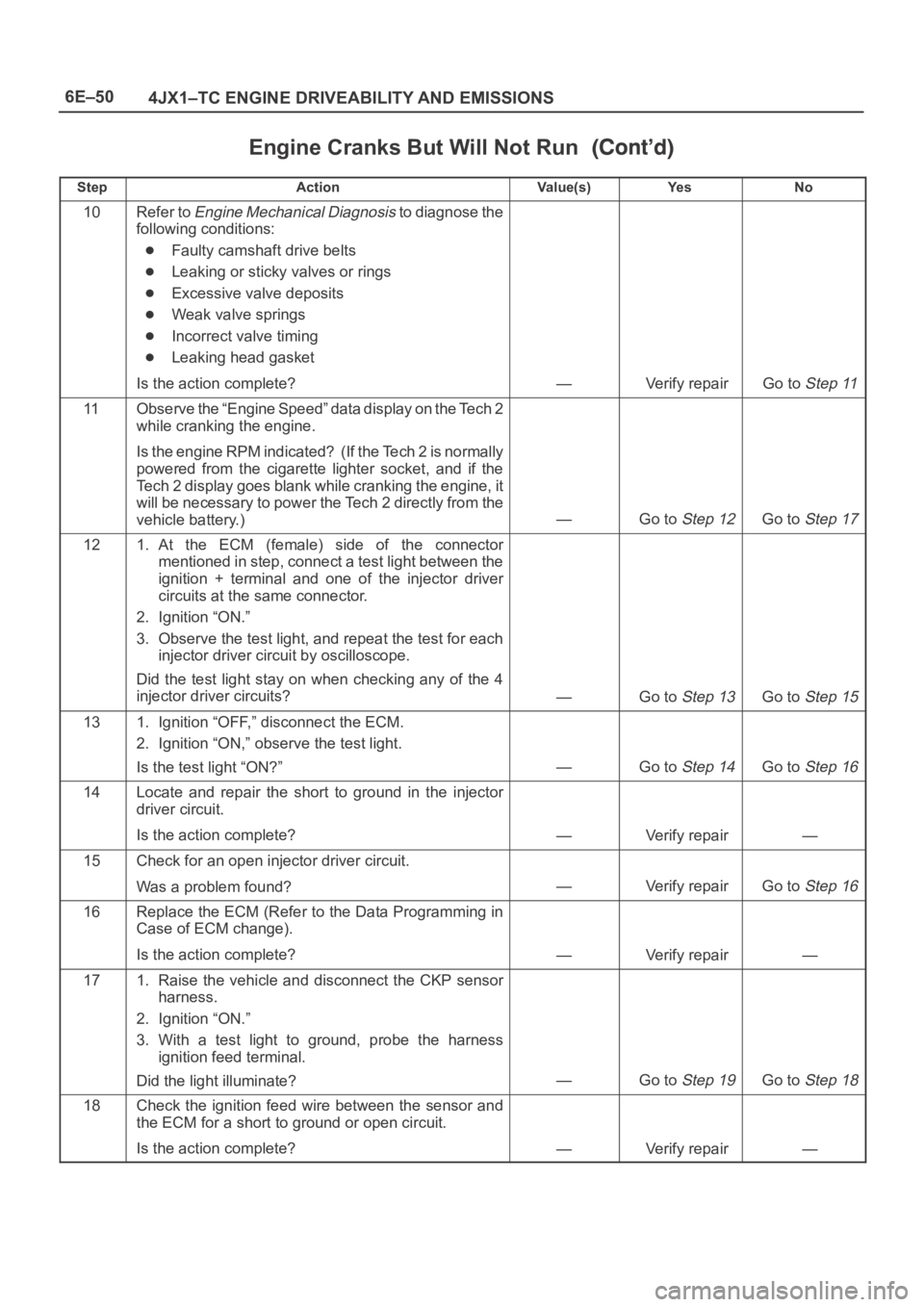
6E–50
4JX1–TC ENGINE DRIVEABILITY AND EMISSIONS
Engine Cranks But Will Not Run
StepNo Ye s Va l u e ( s ) Action
10Refer to Engine Mechanical Diagnosis to diagnose the
following conditions:
Faulty camshaft drive belts
Leaking or sticky valves or rings
Excessive valve deposits
Weak valve springs
Incorrect valve timing
Leaking head gasket
Is the action complete?
—Verify repairGo to Step 11
11Observe the “Engine Speed” data display on the Tech 2
while cranking the engine.
Is the engine RPM indicated? (If the Tech 2 is normally
powered from the cigarette lighter socket, and if the
Tech 2 display goes blank while cranking the engine, it
will be necessary to power the Tech 2 directly from the
vehicle battery.)
—Go to Step 12Go to Step 17
121. At the ECM (female) side of the connector
mentioned in step, connect a test light between the
ignition + terminal and one of the injector driver
circuits at the same connector.
2. Ignition “ON.”
3. Observe the test light, and repeat the test for each
injector driver circuit by oscilloscope.
Did the test light stay on when checking any of the 4
injector driver circuits?
—Go to Step 13Go to Step 15
131. Ignition “OFF,” disconnect the ECM.
2. Ignition “ON,” observe the test light.
Is the test light “ON?”
—Go to Step 14Go to Step 16
14Locate and repair the short to ground in the injector
driver circuit.
Is the action complete?
—Verify repair—
15Check for an open injector driver circuit.
Was a problem found?
—Verify repairGo to Step 16
16Replace the ECM (Refer to the Data Programming in
Case of ECM change).
Is the action complete?
—Verify repair—
171. Raise the vehicle and disconnect the CKP sensor
harness.
2. Ignition “ON.”
3. With a test light to ground, probe the harness
ignition feed terminal.
Did the light illuminate?
—Go to Step 19Go to Step 18
18Check the ignition feed wire between the sensor and
the ECM for a short to ground or open circuit.
Is the action complete?
—Verify repair—
Page 1944 of 6000
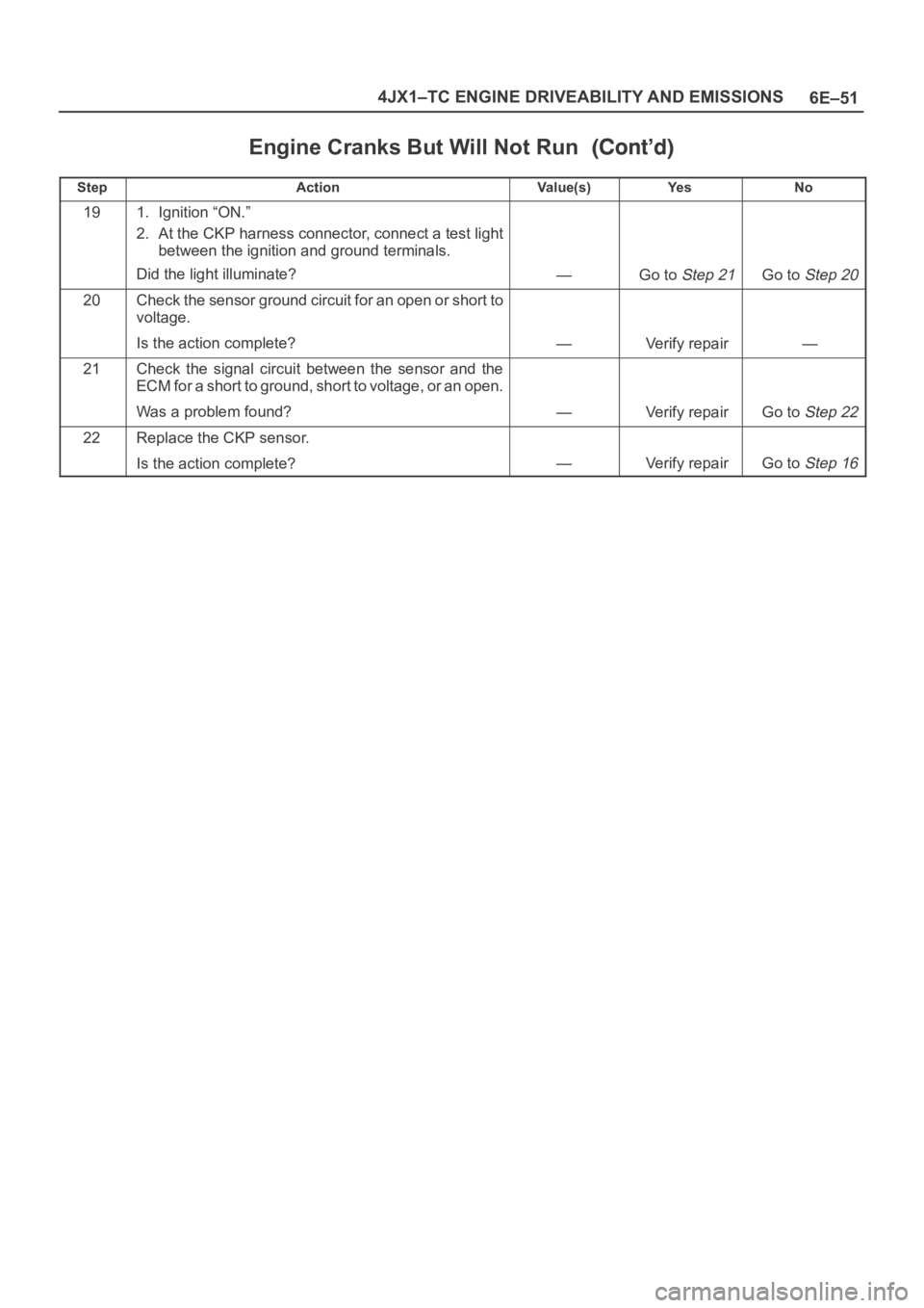
6E–51 4JX1–TC ENGINE DRIVEABILITY AND EMISSIONS
Engine Cranks But Will Not Run
StepNo Ye s Va l u e ( s ) Action
191. Ignition “ON.”
2. At the CKP harness connector, connect a test light
between the ignition and ground terminals.
Did the light illuminate?
—Go to Step 21Go to Step 20
20Check the sensor ground circuit for an open or short to
voltage.
Is the action complete?
—Verify repair—
21Check the signal circuit between the sensor and the
ECM for a short to ground, short to voltage, or an open.
Was a problem found?
—Verify repairGo to Step 22
22Replace the CKP sensor.
Is the action complete?
—Verify repairGo to Step 16
Page 1964 of 6000
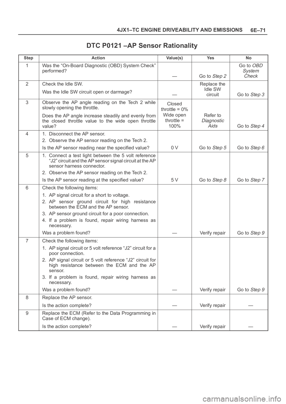
6E–71 4JX1–TC ENGINE DRIVEABILITY AND EMISSIONS
DTC P0121 –AP Sensor Rationality
StepActionVa l u e ( s )Ye sNo
1Was the “On-Board Diagnostic (OBD) System Check”
performed?
—Go to Step 2
Go to OBD
System
Check
2Check the Idle SW.
Was the Idle SW circuit open or darmage?
—
Replace the
Idle SW
circuit
Go to Step 3
3Observe the AP angle reading on the Tech 2 while
slowly opening the throttle.
Does the AP angle increase steadily and evenly from
the closed throttle value to the wide open throttle
value?Closed
throttle = 0%
Wide open
throttle =
100%
Refer to
Diagnostic
Aids
Go to Step 4
41. Disconnect the AP sensor.
2. Observe the AP sensor reading on the Tech 2.
Is the AP sensor reading near the specified value?
0 VGo to Step 5Go to Step 6
51. Connect a test light between the 5 volt reference
“J2” circuit and the AP sensor signal circuit at the AP
sensor harness connector.
2. Observe the AP sensor reading on the Tech 2.
Is the AP sensor reading at the specified value?
5 VGo to Step 8Go to Step 7
6Check the following items:
1. AP signal circuit for a short to voltage.
2. AP sensor ground circuit for high resistance
between the ECM and the AP sensor.
3. AP sensor ground circuit for a poor connection.
4. If a problem is found, repair wiring harness as
necessary.
Was a problem found?
—Verify repairGo to Step 9
7Check the following items:
1. AP signal circuit or 5 volt reference “J2” circuit for a
poor connection.
2. AP signal circuit or 5 volt reference “J2” circuit for
high resistance between the ECM and the AP
sensor.
3. If a problem is found, repair wiring harness as
necessary.
Was a problem found?
—Verify repairGo to Step 9
8Replace the AP sensor.
Is the action complete?
—Verify repair—
9Replace the ECM (Refer to the Data Programming in
Case of ECM change).
Is the action complete?
—Verify repair—