1998 OPEL FRONTERA check engine light
[x] Cancel search: check engine lightPage 3188 of 6000
METER AND GAUGE8E–11
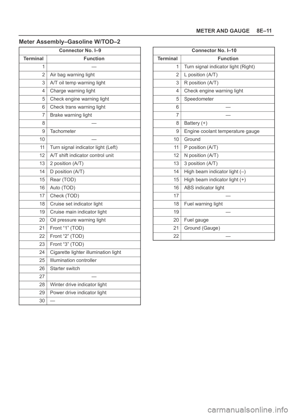
Meter Assembly–Gasoline W/TOD–2
Connector No. I–9
Te r m i n a lFunction
1—
2Air bag warning light
3A/T oil temp warning light
4Charge warning light
5Check engine warning light
6Check trans warning light
7Brake warning light
8—
9Tachometer
10—
11Turn signal indicator light (Left)
12A/T shift indicator control unit
132 position (A/T)
14D position (A/T)
15Rear (TOD)
16Auto (TOD)
17Check (TOD)
18Cruise set indicator light
19Cruise main indicator light
20Oil pressure warning light
21Front “1” (TOD)
22Front “2” (TOD)
23Front “3” (TOD)
24Cigarette lighter illumination light
25Illumination controller
26Starter switch
27—
28Winter drive indicator light
29Power drive indicator light
30—
Connector No. I–10
Te r m i n a lFunction
1Turn signal indicator light (Right)
2L position (A/T)
3R position (A/T)
4Check engine warning light
5Speedometer
6—
7—
8Battery (+)
9Engine coolant temperature gauge
10Ground
11P position (A/T)
12N position (A/T)
133 position (A/T)
14High beam indicator light (–)
15High beam indicator light (+)
16ABS indicator light
17—
18Fuel warning light
19—
20Fuel gauge
21Ground (Gauge)
22—
Page 3196 of 6000
8F–1 BODY STRUCTURE
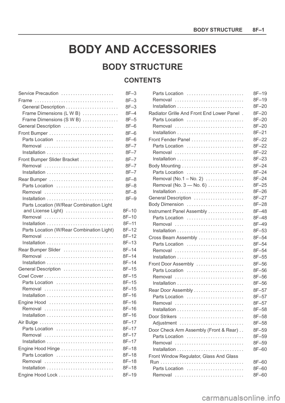
BODY AND ACCESSORIES
BODY STRUCTURE
CONTENTS
Service Precaution 8F–3. . . . . . . . . . . . . . . . . . . . . .
Frame 8F–3. . . . . . . . . . . . . . . . . . . . . . . . . . . . . . . . .
General Description 8F–3. . . . . . . . . . . . . . . . . . . . . .
Frame Dimensions (L W B) 8F–4. . . . . . . . . . . . . . .
Frame Dimensions (S W B) 8F–5. . . . . . . . . . . . . . .
General Description 8F–6. . . . . . . . . . . . . . . . . . . . .
Front Bumper 8F–6. . . . . . . . . . . . . . . . . . . . . . . . . . .
Parts Location 8F–6. . . . . . . . . . . . . . . . . . . . . . . .
Removal 8F–7. . . . . . . . . . . . . . . . . . . . . . . . . . . . .
Installation 8F–7. . . . . . . . . . . . . . . . . . . . . . . . . . . .
Front Bumper Slider Bracket 8F–7. . . . . . . . . . . . . .
Removal 8F–7. . . . . . . . . . . . . . . . . . . . . . . . . . . . .
Installation 8F–7. . . . . . . . . . . . . . . . . . . . . . . . . . . .
Rear Bumper 8F–8. . . . . . . . . . . . . . . . . . . . . . . . . . .
Parts Location 8F–8. . . . . . . . . . . . . . . . . . . . . . . .
Removal 8F–8. . . . . . . . . . . . . . . . . . . . . . . . . . . . .
Installation 8F–9. . . . . . . . . . . . . . . . . . . . . . . . . . . .
Parts Location (W/Rear Combination Light
and License Light) 8F–10. . . . . . . . . . . . . . . . . . . .
Removal 8F–10. . . . . . . . . . . . . . . . . . . . . . . . . . . . .
Installation 8F–11. . . . . . . . . . . . . . . . . . . . . . . . . . . .
Parts Location (W/Rear Combination Light) 8F–12
Removal 8F–12. . . . . . . . . . . . . . . . . . . . . . . . . . . . .
Installation 8F–13. . . . . . . . . . . . . . . . . . . . . . . . . . . .
Rear Bumper Slider 8F–14. . . . . . . . . . . . . . . . . . . . .
Removal 8F–14. . . . . . . . . . . . . . . . . . . . . . . . . . . . .
Installation 8F–14. . . . . . . . . . . . . . . . . . . . . . . . . . . .
General Description 8F–15. . . . . . . . . . . . . . . . . . . . .
Cowl Cover 8F–15. . . . . . . . . . . . . . . . . . . . . . . . . . . . .
Parts Location 8F–15. . . . . . . . . . . . . . . . . . . . . . . .
Removal 8F–15. . . . . . . . . . . . . . . . . . . . . . . . . . . . .
Installation 8F–16. . . . . . . . . . . . . . . . . . . . . . . . . . . .
Engine Hood 8F–16. . . . . . . . . . . . . . . . . . . . . . . . . . .
Removal 8F–16. . . . . . . . . . . . . . . . . . . . . . . . . . . . .
Installation 8F–16. . . . . . . . . . . . . . . . . . . . . . . . . . . .
Air Bulge 8F–17. . . . . . . . . . . . . . . . . . . . . . . . . . . . . . .
Parts Location 8F–17. . . . . . . . . . . . . . . . . . . . . . . .
Removal 8F–17. . . . . . . . . . . . . . . . . . . . . . . . . . . . .
Installation 8F–17. . . . . . . . . . . . . . . . . . . . . . . . . . . .
Engine Hood Hinge 8F–18. . . . . . . . . . . . . . . . . . . . . .
Parts Location 8F–18. . . . . . . . . . . . . . . . . . . . . . . .
Removal 8F–18. . . . . . . . . . . . . . . . . . . . . . . . . . . . .
Installation 8F–18. . . . . . . . . . . . . . . . . . . . . . . . . . . .
Engine Hood Lock 8F–19. . . . . . . . . . . . . . . . . . . . . . . Parts Location 8F–19. . . . . . . . . . . . . . . . . . . . . . . .
Removal 8F–19. . . . . . . . . . . . . . . . . . . . . . . . . . . . .
Installation 8F–20. . . . . . . . . . . . . . . . . . . . . . . . . . . .
Radiator Grille And Front End Lower Panel 8F–20.
Parts Location 8F–20. . . . . . . . . . . . . . . . . . . . . . . .
Removal 8F–20. . . . . . . . . . . . . . . . . . . . . . . . . . . . .
Installation 8F–21. . . . . . . . . . . . . . . . . . . . . . . . . . . .
Front Fender Panel 8F–22. . . . . . . . . . . . . . . . . . . . . .
Parts Location 8F–22. . . . . . . . . . . . . . . . . . . . . . . .
Removal 8F–22. . . . . . . . . . . . . . . . . . . . . . . . . . . . .
Installation 8F–23. . . . . . . . . . . . . . . . . . . . . . . . . . . .
Body Mounting 8F–24. . . . . . . . . . . . . . . . . . . . . . . . . .
Parts Location 8F–24. . . . . . . . . . . . . . . . . . . . . . . .
Removal (No.1 – No. 2) 8F–24. . . . . . . . . . . . . . . .
Removal (No. 3 — No. 6) 8F–25. . . . . . . . . . . . . . .
Installation 8F–26. . . . . . . . . . . . . . . . . . . . . . . . . . . .
General Description 8F–27. . . . . . . . . . . . . . . . . . . . .
Body Dimension 8F–28. . . . . . . . . . . . . . . . . . . . . . . .
Instrument Panel Assembly 8F–48. . . . . . . . . . . . . . .
Parts Location 8F–48. . . . . . . . . . . . . . . . . . . . . . . .
Removal 8F–49. . . . . . . . . . . . . . . . . . . . . . . . . . . . .
Installation 8F–53. . . . . . . . . . . . . . . . . . . . . . . . . . . .
Cross Beam Assembly 8F–54. . . . . . . . . . . . . . . . . . .
Parts Location 8F–54. . . . . . . . . . . . . . . . . . . . . . . .
Removal 8F–54. . . . . . . . . . . . . . . . . . . . . . . . . . . . .
Installation 8F–55. . . . . . . . . . . . . . . . . . . . . . . . . . . .
Front Door Assembly 8F–56. . . . . . . . . . . . . . . . . . . .
Parts Location 8F–56. . . . . . . . . . . . . . . . . . . . . . . .
Removal 8F–56. . . . . . . . . . . . . . . . . . . . . . . . . . . . .
Installation 8F–56. . . . . . . . . . . . . . . . . . . . . . . . . . . .
Rear Door Assembly 8F–57. . . . . . . . . . . . . . . . . . . . .
Parts Location 8F–57. . . . . . . . . . . . . . . . . . . . . . . .
Removal 8F–57. . . . . . . . . . . . . . . . . . . . . . . . . . . . .
Installation 8F–58. . . . . . . . . . . . . . . . . . . . . . . . . . . .
Door Strikers 8F–58. . . . . . . . . . . . . . . . . . . . . . . . . . .
Adjustment 8F–58. . . . . . . . . . . . . . . . . . . . . . . . . . .
Door Check Arm Assembly (Front & Rear) 8F–59. .
Parts Location 8F–59. . . . . . . . . . . . . . . . . . . . . . . .
Removal 8F–59. . . . . . . . . . . . . . . . . . . . . . . . . . . . .
Installation 8F–60. . . . . . . . . . . . . . . . . . . . . . . . . . . .
Front Window Regulator, Glass And Glass
Run 8F–60. . . . . . . . . . . . . . . . . . . . . . . . . . . . . . . . . . .
Parts Location 8F–60. . . . . . . . . . . . . . . . . . . . . . . .
Removal 8F–60. . . . . . . . . . . . . . . . . . . . . . . . . . . . .
Page 3972 of 6000
DIFFERENTIAL (REAR 220mm)
4A2A–3
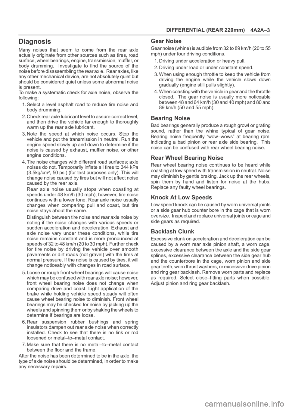
Diagnosis
Many noises that seem to come from the rear axle
actually originate from other sources such as tires, road
surface, wheel bearings, engine, transmission, muffler, or
body drumming. Investigate to find the source of the
noise before disassembling the rear axle. Rear axles, like
any other mechanical device, are not absolutely quiet but
should be considered quiet unless some abnormal noise
is present.
To make a systematic check for axle noise, observe the
following:
1. Select a level asphalt road to reduce tire noise and
body drumming.
2. Check rear axle lubricant level to assure correct level,
and then drive the vehicle far enough to thoroughly
warm up the rear axle lubricant.
3. Note the speed at which noise occurs. Stop the
vehicle and put the transmission in neutral. Run the
engine speed slowly up and down to determine if the
noise is caused by exhaust, muffler noise, or other
engine conditions.
4. Tire noise changes with different road surfaces; axle
noises do not. Temporarily inflate all tires to 344 kPa
(3.5kg/cm
2, 50 psi) (for test purposes only). This will
change noise caused by tires but will not affect noise
caused by the rear axle.
Rear axle noise usually stops when coasting at
speeds under 48 km/h (30 mph); however, tire noise
continues with a lower tone. Rear axle noise usually
changes when comparing pull and coast, but tire
noise stays about the same.
Distinguish between tire noise and rear axle noise by
noting if the noise changes with various speeds or
sudden acceleration and deceleration. Exhaust and
axle noise vary under these conditions, while tire
noise remains constant and is more pronounced at
speeds of 32 to 48 km/h (20 to 30 mph). Further check
for tire noise by driving the vehicle over smooth
pavements or dirt roads (not gravel) with the tires at
normal pressure. If the noise is caused by tires, it will
change noticeably with changes in road surface.
5. Loose or rough front wheel bearings will cause noise
which may be confused with rear axle noise; however,
front wheel bearing noise does not change when
comparing drive and coast. Light application of the
brake while holding vehicle speed steady will often
cause wheel bearing noise to diminish. Front wheel
bearings may be checked for noise by jacking up the
wheels and spinning them or by shaking the wheels to
determine if bearings are loose.
6. Rear suspension rubber bushings and spring
insulators dampen out rear axle noise when correctly
installed. Check to see that there is no link or rod
loosened or metal–to–metal contact.
7. Make sure that there is no metal–to–metal contact
between the floor and the frame.
After the noise has been determined to be in the axle, the
type of axle noise should be determined, in order to make
any necessary repairs.
Gear Noise
Gear noise (whine) is audible from 32 to 89 km/h (20 to 55
mph) under four driving conditions.
1. Driving under acceleration or heavy pull.
2. Driving under load or under constant speed.
3. When using enough throttle to keep the vehicle from
driving the engine while the vehicle slows down
gradually (engine still pulls slightly).
4. When coasting with the vehicle in gear and the throttle
closed. The gear noise is usually more noticeable
between 48 and 64 km/h (30 and 40 mph) and 80 and
89 km/h (50 and 55 mph).
Bearing Noise
Bad bearings generally produce a rough growl or grating
sound, rather than the whine typical of gear noise.
Bearing noise frequently “wow–wows” at bearing rpm,
indicating a bad pinion or rear axle side bearing. This
noise can be confused with rear wheel bearing noise.
Rear Wheel Bearing Noise
Rear wheel bearing noise continues to be heard while
coasting at low speed with transmission in neutral. Noise
may diminish by gentle braking. Jack up the rear wheels,
spin them by hand and listen for noise at the hubs.
Replace any faulty wheel bearings.
Knock At Low Speeds
Low speed knock can be caused by worn universal joints
or a side gear hub counter bore in the cage that is worn
oversize. Inspect and replace universal joints or cage and
side gears as required.
Backlash Clunk
Excessive clunk on acceleration and deceleration can be
caused by a worn rear axle pinion shaft, a worn cage,
excessive clearance between the axle and the side gear
splines, excessive clearance between the side gear hub
and the counterbore in the cage, worn pinion and side
gear teeth, worn thrust washers, or excessive drive pinion
and ring gear backlash. Remove worn parts and replace
as required. Select close–fitting parts when possible.
Adjust pinion and ring gear backlash.
Page 4011 of 6000
4A2B–4DIFFERENTIAL (REAR 244mm)
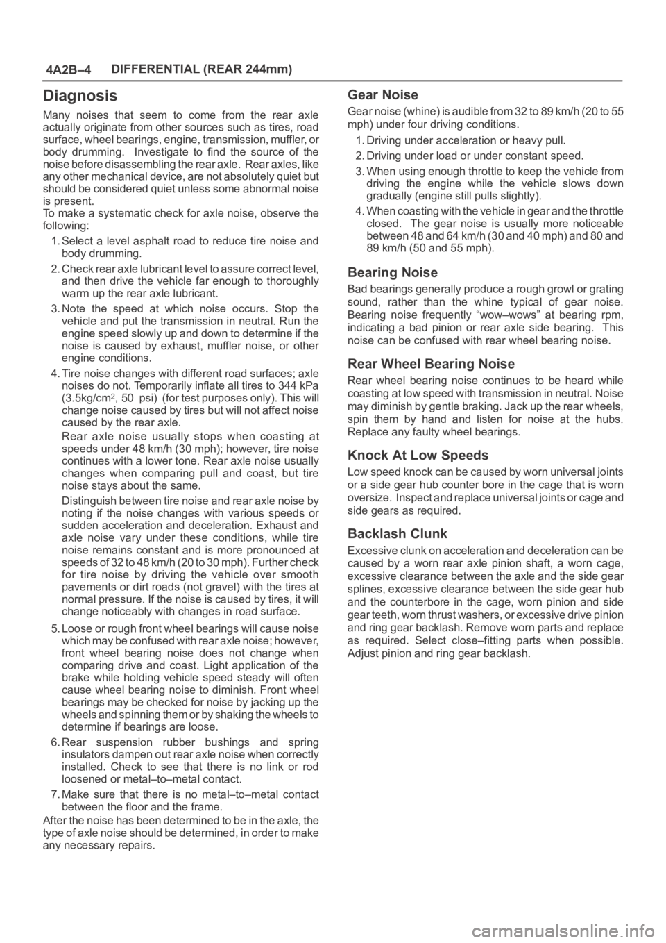
Diagnosis
Many noises that seem to come from the rear axle
actually originate from other sources such as tires, road
surface, wheel bearings, engine, transmission, muffler, or
body drumming. Investigate to find the source of the
noise before disassembling the rear axle. Rear axles, like
any other mechanical device, are not absolutely quiet but
should be considered quiet unless some abnormal noise
is present.
To make a systematic check for axle noise, observe the
following:
1. Select a level asphalt road to reduce tire noise and
body drumming.
2. Check rear axle lubricant level to assure correct level,
and then drive the vehicle far enough to thoroughly
warm up the rear axle lubricant.
3. Note the speed at which noise occurs. Stop the
vehicle and put the transmission in neutral. Run the
engine speed slowly up and down to determine if the
noise is caused by exhaust, muffler noise, or other
engine conditions.
4. Tire noise changes with different road surfaces; axle
noises do not. Temporarily inflate all tires to 344 kPa
(3.5kg/cm
2, 50 psi) (for test purposes only). This will
change noise caused by tires but will not affect noise
caused by the rear axle.
Rear axle noise usually stops when coasting at
speeds under 48 km/h (30 mph); however, tire noise
continues with a lower tone. Rear axle noise usually
changes when comparing pull and coast, but tire
noise stays about the same.
Distinguish between tire noise and rear axle noise by
noting if the noise changes with various speeds or
sudden acceleration and deceleration. Exhaust and
axle noise vary under these conditions, while tire
noise remains constant and is more pronounced at
speeds of 32 to 48 km/h (20 to 30 mph). Further check
for tire noise by driving the vehicle over smooth
pavements or dirt roads (not gravel) with the tires at
normal pressure. If the noise is caused by tires, it will
change noticeably with changes in road surface.
5. Loose or rough front wheel bearings will cause noise
which may be confused with rear axle noise; however,
front wheel bearing noise does not change when
comparing drive and coast. Light application of the
brake while holding vehicle speed steady will often
cause wheel bearing noise to diminish. Front wheel
bearings may be checked for noise by jacking up the
wheels and spinning them or by shaking the wheels to
determine if bearings are loose.
6. Rear suspension rubber bushings and spring
insulators dampen out rear axle noise when correctly
installed. Check to see that there is no link or rod
loosened or metal–to–metal contact.
7. Make sure that there is no metal–to–metal contact
between the floor and the frame.
After the noise has been determined to be in the axle, the
type of axle noise should be determined, in order to make
any necessary repairs.
Gear Noise
Gear noise (whine) is audible from 32 to 89 km/h (20 to 55
mph) under four driving conditions.
1. Driving under acceleration or heavy pull.
2. Driving under load or under constant speed.
3. When using enough throttle to keep the vehicle from
driving the engine while the vehicle slows down
gradually (engine still pulls slightly).
4. When coasting with the vehicle in gear and the throttle
closed. The gear noise is usually more noticeable
between 48 and 64 km/h (30 and 40 mph) and 80 and
89 km/h (50 and 55 mph).
Bearing Noise
Bad bearings generally produce a rough growl or grating
sound, rather than the whine typical of gear noise.
Bearing noise frequently “wow–wows” at bearing rpm,
indicating a bad pinion or rear axle side bearing. This
noise can be confused with rear wheel bearing noise.
Rear Wheel Bearing Noise
Rear wheel bearing noise continues to be heard while
coasting at low speed with transmission in neutral. Noise
may diminish by gentle braking. Jack up the rear wheels,
spin them by hand and listen for noise at the hubs.
Replace any faulty wheel bearings.
Knock At Low Speeds
Low speed knock can be caused by worn universal joints
or a side gear hub counter bore in the cage that is worn
oversize. Inspect and replace universal joints or cage and
side gears as required.
Backlash Clunk
Excessive clunk on acceleration and deceleration can be
caused by a worn rear axle pinion shaft, a worn cage,
excessive clearance between the axle and the side gear
splines, excessive clearance between the side gear hub
and the counterbore in the cage, worn pinion and side
gear teeth, worn thrust washers, or excessive drive pinion
and ring gear backlash. Remove worn parts and replace
as required. Select close–fitting parts when possible.
Adjust pinion and ring gear backlash.
Page 4070 of 6000
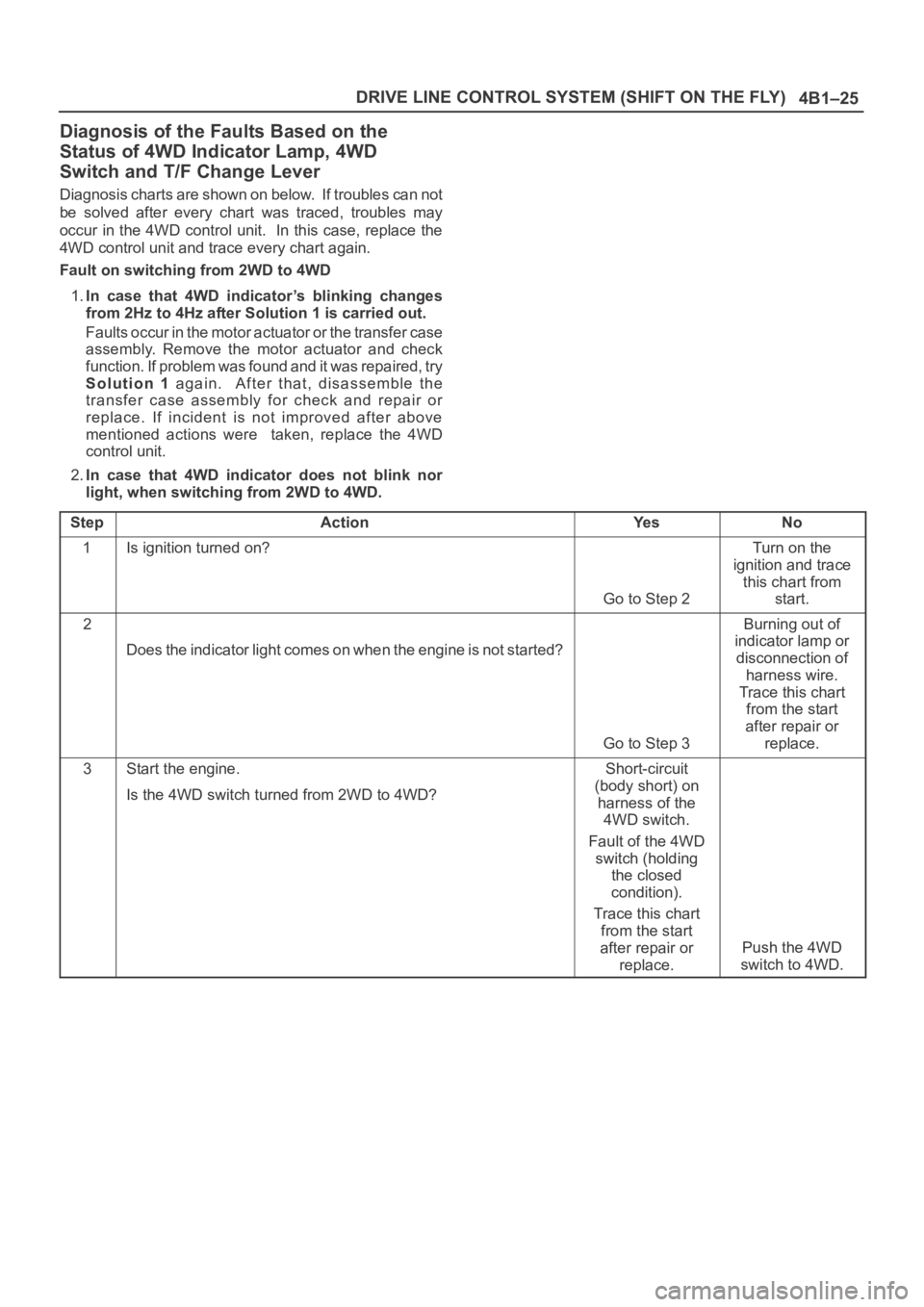
4B1–25 DRIVE LINE CONTROL SYSTEM (SHIFT ON THE FLY)
Diagnosis of the Faults Based on the
Status of 4WD Indicator Lamp, 4WD
Switch and T/F Change Lever
Diagnosis charts are shown on below. If troubles can not
be solved after every chart was traced, troubles may
occur in the 4WD control unit. In this case, replace the
4WD control unit and trace every chart again.
Fault on switching from 2WD to 4WD
1.In case that 4WD indicator’s blinking changes
from 2Hz to 4Hz after Solution 1 is carried out.
Faults occur in the motor actuator or the transfer case
assembly. Remove the motor actuator and check
function. If problem was found and it was repaired, try
Solution 1 again. After that, disassemble the
transfer case assembly for check and repair or
replace. If incident is not improved after above
mentioned actions were taken, replace the 4WD
control unit.
2.In case that 4WD indicator does not blink nor
light, when switching from 2WD to 4WD.
Step
ActionYe sNo
1Is ignition turned on?
Go to Step 2
Turn on the
ignition and trace
this chart from
start.
2
Does the indicator light comes on when the engine is not started?
Go to Step 3
Burning out of
indicator lamp or
disconnection of
harness wire.
Trace this chart
from the start
after repair or
replace.
3Start the engine.
Is the 4WD switch turned from 2WD to 4WD?Short-circuit
(body short) on
harness of the
4WD switch.
Fault of the 4WD
switch (holding
the closed
condition).
Trace this chart
from the start
after repair or
replace.
Push the 4WD
switch to 4WD.
Page 4120 of 6000
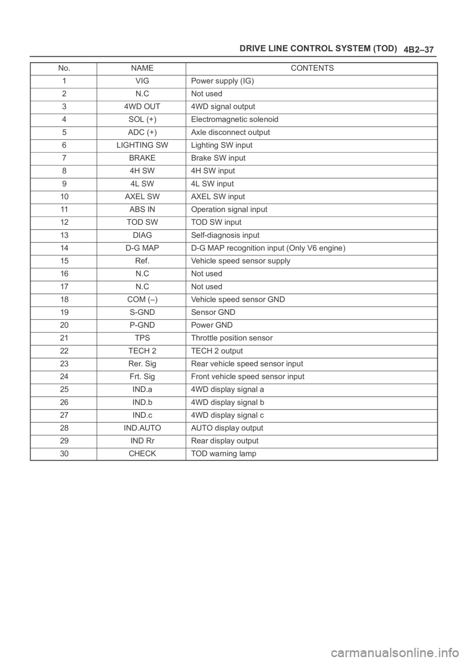
4B2–37 DRIVE LINE CONTROL SYSTEM (TOD)
No.NAMECONTENTS
1VIGPower supply (IG)
2N.CNot used
34WD OUT4WD signal output
4SOL (+)Electromagnetic solenoid
5ADC (+)Axle disconnect output
6LIGHTING SWLighting SW input
7BRAKEBrake SW input
84H SW4H SW input
94L SW4L SW input
10AXEL SWAXEL SW input
11ABS INOperation signal input
12TOD SWTOD SW input
13DIAGSelf-diagnosis input
14D-G MAPD-G MAP recognition input (Only V6 engine)
15Ref.Vehicle speed sensor supply
16N.CNot used
17N.CNot used
18COM (–)Vehicle speed sensor GND
19S-GNDSensor GND
20P-GNDPower GND
21TPSThrottle position sensor
22TECH 2TECH 2 output
23Rer. SigRear vehicle speed sensor input
24Frt. SigFront vehicle speed sensor input
25IND.a4WD display signal a
26IND.b4WD display signal b
27IND.c4WD display signal c
28IND.AUTOAUTO display output
29IND RrRear display output
30CHECKTOD warning lamp
Page 4122 of 6000
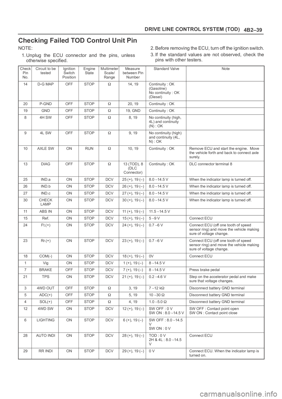
4B2–39 DRIVE LINE CONTROL SYSTEM (TOD)
Checking Failed TOD Control Unit Pin
NOTE:
1. Unplug the ECU connector and the pins, unless
otherwise specified.2. Before removing the ECU, turn off the ignition switch.
3. If the standard values are not observed, check the
pins with other testers.
Check
Pin
No.Circuit to be
testedIgnition
Switch
PositionEngine
StateMultimeter
Scale/
RangeMeasure
between Pin
NumberStandard ValveNote
14D-G MAPOFFSTOP14, 19Continuity : OK
(Gasoline)
No continuity : OK
(Diesel)
20P-GNDOFFSTOP20, 19Continuity : OK
19GNDOFFSTOP19, GNDContinuity : OK
84H SWOFFSTOP8, 19No continuity (high,
4L) and continuity
(N) : OK
94L SWOFFSTOP9, 19No continuity (high)
and continuity (4L,
N) : OK
10AXLE SWONRUN10, 19Continuity : OKRemove ECU and start the engine. Move
the vehicle forth and back to connect axle
surely.
13DIAGOFFSTOP13 (TOD), 8
(DLC
Connector)Continuity : OKDLC connector terminal 8
25IND.aONSTOPDCV25 (+), 19 (–)8.0 14.5 VWhen the indicator lamp is turned off.
26IND.bONSTOPDCV26 (+), 19 (–)8.0 14.5 VWhen the indicator lamp is turned off.
27IND.cONSTOPDCV27 (+), 19 (–)8.0 14.5 VWhen the indicator lamp is turned off.
30CHECK
LAMPONSTOPDCV30 (+), 19 (–)8.0 14.5 VWhen the indicator lamp is turned off.
11ABS INONSTOPDCV11 (+), 19 (–)11 . 5 14.5 V
15Ref.ONSTOPDCV15 (+), 19 (–)5 9 VConnect ECU
24Ft.(+)ONSTOPDCV24 (+), 19 (–)0.7 6 VConnect ECU (off one tooth of speed
sensor ring) and move the vehicle making
sure of voltage change.
23Rr.(+)ONSTOPDCV23 (+), 19 (–)0.7 6 VConnect ECU (off one tooth of speed
sensor ring) and move the vehicle making
sure of voltage change.
18COM(-)ONSTOPDCV18 (+), 19 (–)0VConnect ECU
1VigONSTOPDCV1 (+), 19 (–)8 14.5 V
7BRAKEOFFSTOPDCV7 (+), 19 (–)8 14.5 VPress brake pedal
21TPSONSTOPDCV21 (+), 19 (–)0.2 4.6 VStep on the accelerator pedal and make
sure that voltage changes.
34WD OUTOFFSTOP3, 197 12 kDisconnect battery GND terminal
5ADC(+)OFFSTOP5, 1910 30 Disconnect battery GND terminal
4SOL(+)OFFSTOP4, 191.0 5.0 Disconnect battery GND terminal
124WD SWONSTOPDCV12 (+), 19 (–)SW OFF : 0 V
SW ON : 8.0 14.5 VSW OFF : Contact point open
SW ON : Contact point close
6LIGHTINGONSTOPDCV6 (+), 19 (–)SW OFF : 8.0 14.5
V
SW ON : 0 V
28AUTO INDIONSTOPDCV28 (+), 19 (–)TOD : 0 V
2H & 4L : 8.0 14.5
VConnect ECU
29RR INDIONSTOPDCV29 (+), 19 (–)0 VConnect ECU. When the indicator lamp is
turned on.
Page 4351 of 6000
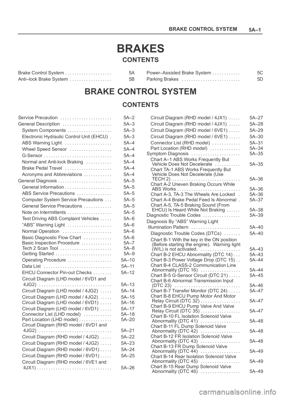
5A–1 BRAKE CONTROL SYSTEM
BRAKES
CONTENTS
Brake Control System 5A. . . . . . . . . . . . . . . . . . . .
Anti–lock Brake System 5B. . . . . . . . . . . . . . . . . . Power–Assisted Brake System 5C. . . . . . . . . . . .
Parking Brakes 5D. . . . . . . . . . . . . . . . . . . . . . . . .
BRAKE CONTROL SYSTEM
CONTENTS
Service Precaution 5A–2. . . . . . . . . . . . . . . . . . . . . .
General Description 5A–3. . . . . . . . . . . . . . . . . . . . .
System Components 5A–3. . . . . . . . . . . . . . . . . . .
Electronic Hydraulic Control Unit (EHCU) 5A–3.
ABS Warning Light 5A–4. . . . . . . . . . . . . . . . . . . .
Wheel Speed Sensor 5A–4. . . . . . . . . . . . . . . . . .
G-Sensor 5A–4. . . . . . . . . . . . . . . . . . . . . . . . . . . . .
Normal and Anti-lock Braking 5A–4. . . . . . . . . . .
Brake Pedal Travel 5A–4. . . . . . . . . . . . . . . . . . . .
Acronyms and Abbreviations 5A–4. . . . . . . . . . . .
General Diagnosis 5A–5. . . . . . . . . . . . . . . . . . . . . . .
General Information 5A–5. . . . . . . . . . . . . . . . . . . .
ABS Service Precautions 5A–5. . . . . . . . . . . . . . .
Computer System Service Precautions 5A–5. . .
General Service Precautions 5A–5. . . . . . . . . . . .
Note on Intermittents 5A–5. . . . . . . . . . . . . . . . . . .
Test Driving ABS Complaint Vehicles 5A–6. . . . .
“ABS” Warning Light 5A–6. . . . . . . . . . . . . . . . . . .
Normal Operation 5A–6. . . . . . . . . . . . . . . . . . . . .
Basic Diagnostic Flow Chart 5A–6. . . . . . . . . . . .
Basic Inspection Procedure 5A–7. . . . . . . . . . . . .
Tech 2 Scan Tool 5A–8. . . . . . . . . . . . . . . . . . . . . .
Getting Started 5A–9. . . . . . . . . . . . . . . . . . . . . . . .
Operating Procedure 5A–10. . . . . . . . . . . . . . . . . . .
Data List 5A–11. . . . . . . . . . . . . . . . . . . . . . . . . . . . .
EHCU Connector Pin-out Checks 5A–12. . . . . . . .
Circuit Diagram (LHD model / 6VD1 and
4JG2) 5A–13. . . . . . . . . . . . . . . . . . . . . . . . . . . . . . .
Circuit Diagram (LHD model / 4JG2) 5A–14. . . . .
Circuit Diagram (LHD model / 4JG2) 5A–15. . . . .
Circuit Diagram (LHD model / 6VD1) 5A–16. . . . .
Circuit Diagram (LHD model / 6VD1) 5A–17. . . . .
Connector List (LHD model) 5A–18. . . . . . . . . . . .
Part Location (LHD model) 5A–20. . . . . . . . . . . . . .
Circuit Diagram (RHD model / 6VD1 and
4JG2) 5A–21. . . . . . . . . . . . . . . . . . . . . . . . . . . . . . .
Circuit Diagram (RHD model / 4JG2) 5A–22. . . . .
Circuit Diagram (RHD model / 4JG2) 5A–23. . . . .
Circuit Diagram (RHD model / 6VD1) 5A–24. . . . .
Circuit Diagram (RHD model / 6VD1) 5A–25. . . . .
Circuit Diagram (RHD model / 6VE1 and
4JX1) 5A–26. . . . . . . . . . . . . . . . . . . . . . . . . . . . . . . . Circuit Diagram (RHD model / 4JX1) 5A–27. . . . .
Circuit Diagram (RHD model / 4JX1) 5A–28. . . . .
Circuit Diagram (RHD model / 6VE1) 5A–29. . . . .
Circuit Diagram (RHD model / 6VE1) 5A–30. . . . .
Connector List (RHD model) 5A–31. . . . . . . . . . . .
Part Location (RHD model) 5A–34. . . . . . . . . . . . .
Symptom Diagnosis 5A–35. . . . . . . . . . . . . . . . . . . . .
Chart A–1 ABS Works Frequently But
Vehicle Does Not Decelerate 5A–35. . . . . . . . . . .
Chart TA-1 ABS Works Frequently But
Vehicle Does Not Decelerate (Use
TECH 2) 5A–36. . . . . . . . . . . . . . . . . . . . . . . . . . . . .
Chart A-2 Uneven Braking Occurs While
ABS Works 5A–36. . . . . . . . . . . . . . . . . . . . . . . . . . .
Chart A-3, TA-3 The Wheels Are Locked 5A–36.
Chart A-4 Brake Pedal Feed Is Abnormal 5A–37.
Chart A-5, TA-5 Braking Sound (From
EHCU) Is Heard While Not Braking 5A–38. . . . . .
Diagnostic Trouble Codes 5A–39. . . . . . . . . . . . . . . .
Diagnosis By “ABS” Warning Light
Illumination Pattern 5A–40. . . . . . . . . . . . . . . . . . . . .
Diagnostic Trouble Codes (DTCs) 5A–40. . . . . . .
Chart B-1 With the key in the ON position
(Before starting the engine). Warning light
(W/L) is not activated. 5A–43. . . . . . . . . . . . . . . . .
Chart B-2 EHCU Abnormality (DTC 14) 5A–43. . .
Chart B-3 Power Voltage Drop (DTC 15) 5A–44. .
Chart B-4 CLASS-2 Communication Line
Abnormality (DTC 16) 5A–44. . . . . . . . . . . . . . . . .
Chart B-5 G-Sensor Circuit (DTC 21) 5A–45. . . . .
Chart B-6 Abnormal Transmission Input
(DTC 23) 5A–46. . . . . . . . . . . . . . . . . . . . . . . . . . . .
Chart B-7 Transfer Monitor (DTC 24) 5A–47. . . . .
Chart B-8 EHCU Pump Motor And Motor
Relay Circuit (DTC 32) 5A–47. . . . . . . . . . . . . . . . .
Chart B-9 EHCU Pump Valve And Valve
Relay Circuit (DTC 35) 5A–47. . . . . . . . . . . . . . . . .
Chart B-10 FL Isolation Solenoid Valve
Abnormality (DTC 41) 5A–48. . . . . . . . . . . . . . . . .
Chart B-11 FL Dump Solenoid Valve
Abnormality (DTC 42) 5A–48. . . . . . . . . . . . . . . . .
Chart B-12 FR Isolation Solenoid Valve
Abnormality (DTC 43) 5A–48. . . . . . . . . . . . . . . . .
Chart B-13 FR Dump Solenoid Valve
Abnormality (DTC 44) 5A–49. . . . . . . . . . . . . . . . .
Chart B-14 Rear Isolation Solenoid Valve
Abnormality (DTC 45) 5A–49. . . . . . . . . . . . . . . . .
Chart B-15 Rear Dump Solenoid Valve
Abnormality (DTC 46) 5A–49. . . . . . . . . . . . . . . . .