Page 2182 of 6000

7A–28
AUTOMATIC TRANSMISSION (4L30–E)
Removal
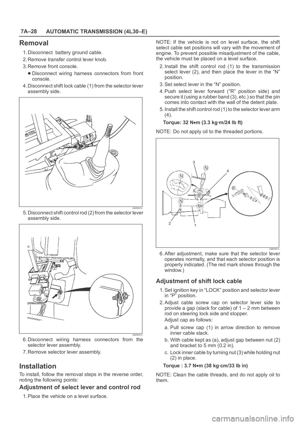
1. Disconnect battery ground cable.
2. Remove transfer control lever knob.
3. Remove front console.
Disconnect wiring harness connectors from front
console.
4. Disconnect shift lock cable (1) from the selector lever
assembly side.
256RW012
5. Disconnect shift control rod (2) from the selector lever
assembly side.
256RW013
6. Disconnect wiring harness connectors from the
selector lever assembly.
7. Remove selector lever assembly.
Installation
To install, follow the removal steps in the reverse order,
noting the following points:
Adjustment of select lever and control rod
1. Place the vehicle on a level surface.NOTE: If the vehicle is not on level surface, the shift
select cable set positions will vary with the movement of
engine. To prevent possible misadjustment of the cable,
the vehicle must be placed on a level surface.
2. Install the shift control rod (1) to the transmission
select lever (2), and then place the lever in the “N”
position.
3. Set select lever in the “N” position.
4. Push select lever forward (“R” position side) and
s e c u r e i t ( u s i n g a r u b b e r b a n d ( 3 ) , e t c . ) s o t h a t t h e p i n
comes into contact with the wall of the detent plate.
5. Install the shift control rod (1) to the selector lever arm
(4).
To r q u e : 3 2 N
m (3.3 kgꞏm/24 lb ft)
NOTE: Do not apply oil to the threaded portions.
256RW014
6. After adjustment, make sure that the selector lever
operates normally, and that each selector position is
properly indicated. (The red mark shows through the
window.)
Adjustment of shift lock cable
1. Set ignition key in “LOCK” position and selector lever
in “P” position.
2. Adjust cable screw cap on selector lever side to
provide a gap (slack for cable) of 1 – 2 mm between
rod on steering lock side and stopper.
Adjust cap as follows:
a. Pull screw cap (1) in arrow direction to remove
inner cable slack.
b. With cable kept as (a), adjust gap between nut (2)
and bracket to 5 mm (0.2 in).
c. Lock inner cable by turning nut (3) while holding nut
(2) in place.
Torque : 3.7 N
m (38 kgꞏcm/33 lb in)
NOTE: Clean the cable threads, and do not apply oil to
them.
Page 2347 of 6000
MANUAL TRANSMISSION7B–29
2. Using remover 5–8840–2551–0 (J–42795) and
attachment 5–8840–2560–0 (J–42988), remove
counter gear shaft center bearing.
NOTE: Be careful not to drop the counter gear, when
removing the bearing.
226RW199
3. Remove the counter gear from intermediate
plate.
226RW030
19. Disassemble the counter gear shaft assembly.
1. Using snap ring pliers, remove the counter gear
shaft front bearing snap ring.
226RW065
2. Using bearing separator 5–8840–0015–0
(J–22912–01) and a press, remove the bearing.
226RW200
Page 2368 of 6000
7B–50MANUAL TRANSMISSION
15. Inspect each gear radial clearance.
1. Mount the mainshaft through the aluminum plate
in a vise.
2. Using a dial indicator, measure the radial
clearance of each gear.
Gear
Standard Clearanse
1st0.020 – 0.073 mm (0.0008 – 0.0029 in)
2nd0.015 – 0.068 mm (0.0006 – 0.0027 in)
3rd0.015 – 0.068 mm (0.0006 – 0.0027 in)
226RW071
16. Install the counter gear shaft.
1. Check the new counter front bearing inner race
and the side race, as shown.
2. Using installer 5–8840–2556–0 (J–42800) and a
press, install the counter gear shaft front bearing.
226RW194
3. Select a snap ring that will allow minimum axial
play.
Mark
Thickness
A2.00–2.05mm (0.079–0.081in)
B2.05–2.10mm (0.081–0.083in)
C2.10–2.15mm (0.083–0.085in)
D2.15–2.20mm (0.085–0.087in)
E2.20–2.25mm (0.087–0.089in)
F2.25–2.30mm (0.089–0.091in)
226RW128
4. Using a snap ring expander, install the new snap
ring.
226RW129
Page 2381 of 6000
MANUAL TRANSMISSION7B–63
3. Stand the transmission by the wood blocks.
4. Using a plastic hammer, tap the transmission
case and attach it to the intermediate plate.
NOTE: Be careful not to add over force to bearing.
220RW022
5. Using a snap ring expander, install the front
bearing shaft snap ring (1) and counter gear shaft
bearing snap ring (2).
226RW004
6. Turn over the transmission.
35. Install the front cover.
1. Clean up the fitting surface.
2. Apply recommended liquid gasket (THREE
BOND 1281 or equivalent), as shown.NOTE:
Don’t dry the liquid gasket.
220RW025
3. Clean up and dry the bolts.
4. Apply thread sealant (THREE BOND 1344 or
equivalent) to the 8 bolts.
5. Using 8 bolts, install the front cover to the
transmission case.
Torque: 17 Nꞏm (1.7 kgꞏm/12 lb ft)
NOTE:
Tighten the all bolts evenly.
Be careful not to damage the oil seal.
220RW018
Page 2390 of 6000
7B–72MANUAL TRANSMISSION
Special Tools
ILLUSTRATIONTOOL NO.
TOOL NAME
5–8840–2550–0
(J–42794)
Gear spline pieace
remover
5–8840–2551–0
(J–42795)
Center bearing remover
5–8840–2560–0
(J–42988)
Attachment
5–8840–2552–0
(J–42796)
Counter gear shaft
center bearing installer
5–8840–2553–0
(J–42797)
Clutch hub (No.2)
installer
5–8840–2554–0
(J–42798)
Clutch hub (No.1)
installer
ILLUSTRATIONTOOL NO.
TOOL NAME
5–8840–2555–0
(J–42799)
Installer
5–8840–2556–0
(J–42800)
Counter gear shaft front
bearing installer
5–8840–2559–0
(J–42904)
Top gear shaft front
bearing installer
5–8840–2557–0
(J–42801)
Front rerainer oil seal
installer
5–8840–2558–0
(J–42802)
Transfer adapter oil seal
installer
5–8840–0007–0
(J–8092)
Driver handle
Page 2524 of 6000

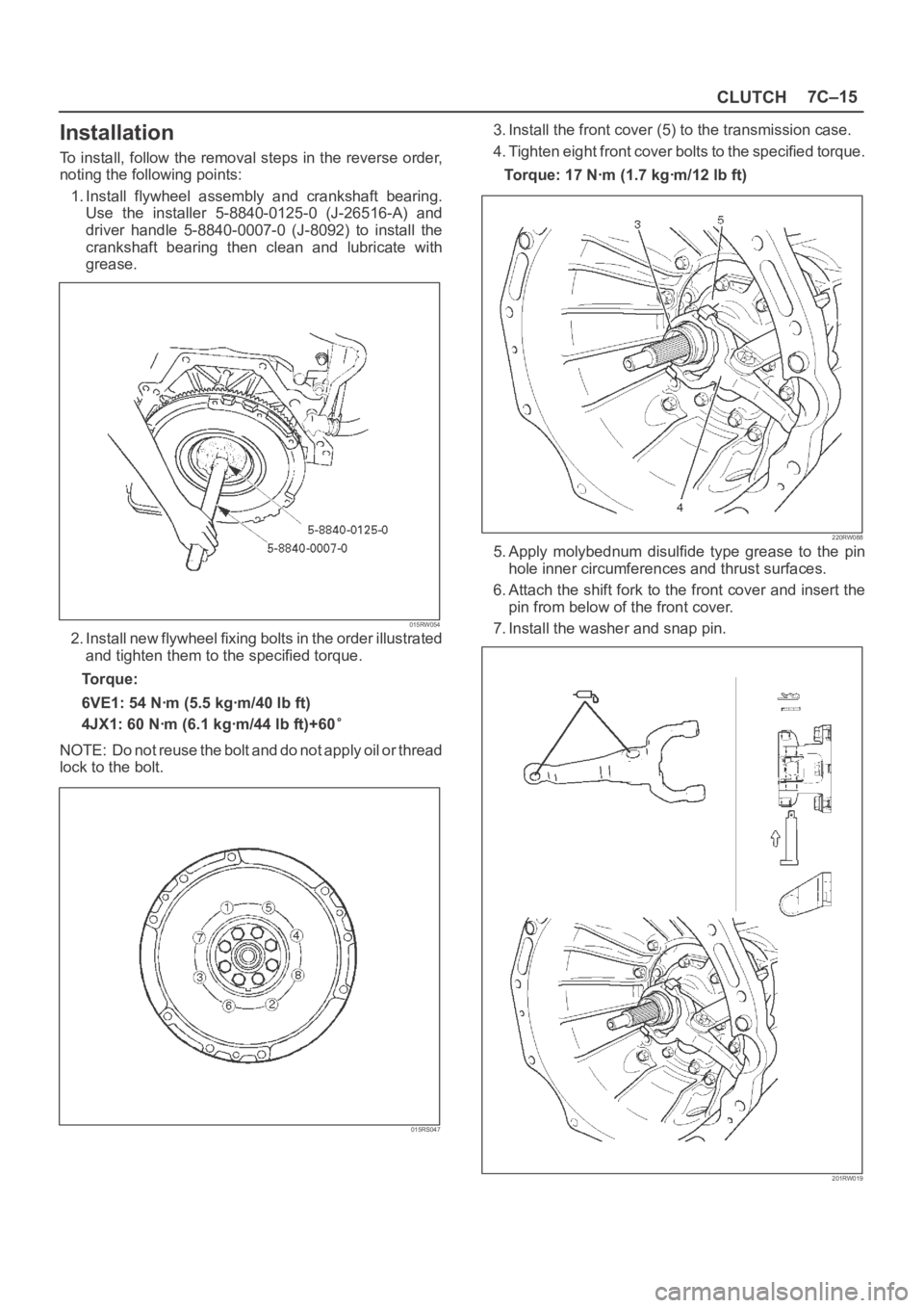
CLUTCH7C–15
Installation
To install, follow the removal steps in the reverse order,
noting the following points:
1. Install flywheel assembly and crankshaft bearing.
Use the installer 5-8840-0125-0 (J-26516-A) and
driver handle 5-8840-0007-0 (J-8092) to install the
crankshaft bearing then clean and lubricate with
grease.
015RW054
2. Install new flywheel fixing bolts in the order illustrated
and tighten them to the specified torque.
Torque:
6VE1: 54 Nꞏm (5.5 kgꞏm/40 lb ft)
4JX1: 60 Nꞏm (6.1 kgꞏm/44 lb ft)+60
NOTE: Do not reuse the bolt and do not apply oil or thread
lock to the bolt.
015RS047
3. Install the front cover (5) to the transmission case.
4. Tighten eight front cover bolts to the specified torque.
Torque: 17 Nꞏm (1.7 kgꞏm/12 lb ft)
220RW088
5. Apply molybednum disulfide type grease to the pin
hole inner circumferences and thrust surfaces.
6. Attach the shift fork to the front cover and insert the
pin from below of the front cover.
7. Install the washer and snap pin.
201RW019
Page 3179 of 6000
8E–2METER AND GAUGE
Meter Assembly
General Description
The meter assembly has the speedometer, tachometer,
engine coolant temperature gauge, fuel gauge and
warning/indicator lights. In addition, the meter assembly
containing TOD (Torque on Demand) has the TOD
indicator light, or the meter assembly not containing TOD
has the voltmeter and oil pressure gauge instead of the
TOD indicator.
Layout for Meters/Gauges, Warning Lights, Indicator Lights and Illumination
Lights
Meter Assembly–Gasoline W/O TOD (Front View)
825RW207
Legend
(1) Voltmeter & Engine Coolant Temperature
Gauge
(2) Tachometer
(3) Warning Light Lens
(4) Speedometer(5) Oil Pressure Gauge & Fuel Gauge
(6) Warning Light Lens
(7) Reset Knob
(8) A/T Shift Indicator
(9) Warning Light Lens
Page 3181 of 6000
8E–4METER AND GAUGE
Meter Assembly–Gasoline W/TOD (Front View)
825RW210
Legend
(1) TOD Indicator
(2) Tachometer
(3) Warning Light Lens
(4) Speedometer(5) Coolant Temperature Gauge & Fuel Gauge
(6) Warning Light Lens
(7) Reset Knob
(8) A/T Shift Indicator
(9) Warning Light Lens