Page 4017 of 6000
4A2B–10DIFFERENTIAL (REAR 244mm)
6. Install snap ring.
7. Install axle shaft assembly.
NOTE: Be sure not to damage the oil seal.
8. Tighten the bearing holder mounting nut to the
specified torque.
Torque: 74Nꞏm (54 Ib ft)
9. Fix the parking brake cable mounting bolt (Behind the
back plate).10. Install parking brake assembly, refer to Parking
Brakes in Brake section.
11. Install antilock brake system sensor.
12. Install brake disc.
13. Install brake caliper, refer to Disk Brakes in Brake
section.
Pinion Oil Seal
Pinion Oil Seal and Associated Parts
425RY00010
Legend
(1) Flange Nut and Washer
(2) Flange(3) Oil Seal
(4) Outer Bearing
(5) Collapsible Spacer
Removal
1.Remove the rear propeller shaft. Refer to Rear
Propeller Shaft in this section.
2. Drain the rear axle oil.
Page 4019 of 6000
4A2B–12DIFFERENTIAL (REAR 244mm)
Differential Assembly
Differential Assembly and Associated Parts
425RY00016
Legend
(1) Bolt and Nut
(2) Axle Shaft Assembly(3) Parking Brake Cable
(4) Differential Assembly
(5) Nut
Removal
1. Jack up and support the frame with stands.
2. Remove the wheel and tire. Refer to Wheel in
Steering section.
3. Drain the differential oil.
4. Remove the propeller shaft. Refer to Rear Propeller
Shaft in this section.
5. Remove the ABS speed sensor. Refer to Anti–lock
Brake System in Brakes section.6. Remove the parking brake cable fastening clip and
disconnect the equalizer section. Refer to Parking
Brakes in Brake section.
7. Remove the bearing holder fixing nuts.
8. Remove axle shaft assembly, be sure not to damage
the oil seal by axle shaft.
9. Remove differential carrier mounting bolts and nuts.
10. Remove differential assembly.
Page 4085 of 6000

DRIVE LINE CONTROL SYSTEM (TOD) 4B2–2
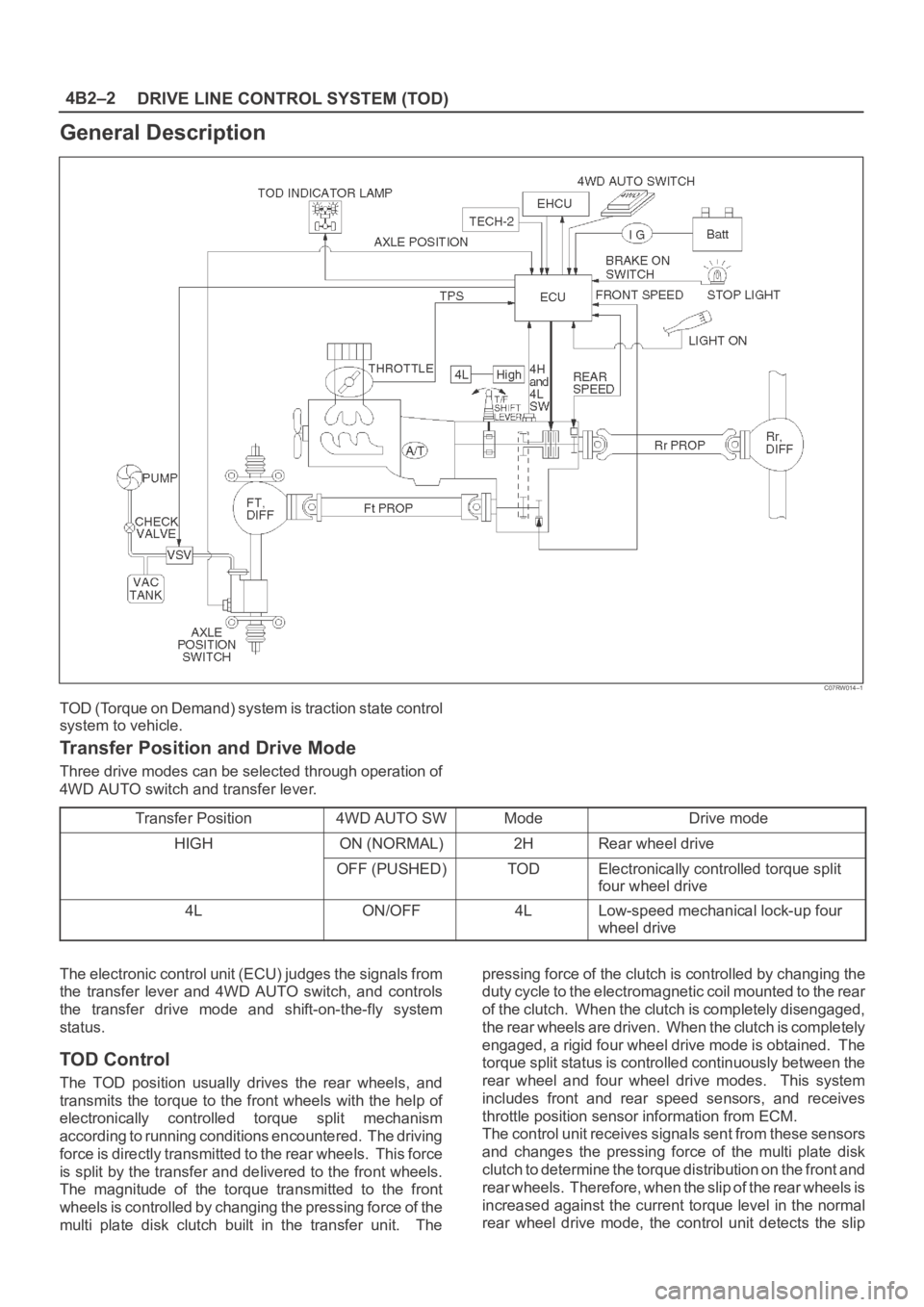
General Description
C07RW014–1
TOD (Torque on Demand) system is traction state control
system to vehicle.
Transfer Position and Drive Mode
Three drive modes can be selected through operation of
4WD AUTO switch and transfer lever.
Transfer Position
4WD AUTO SWModeDrive mode
HIGHON (NORMAL)2HRear wheel drive
OFF (PUSHED)TODElectronically controlled torque split
four wheel drive
4LON/OFF4LLow-speed mechanical lock-up four
wheel drive
The electronic control unit (ECU) judges the signals from
the transfer lever and 4WD AUTO switch, and controls
the transfer drive mode and shift-on-the-fly system
status.
TOD Control
The TOD position usually drives the rear wheels, and
transmits the torque to the front wheels with the help of
electronically controlled torque split mechanism
according to running conditions encountered. The driving
force is directly transmitted to the rear wheels. This force
is split by the transfer and delivered to the front wheels.
The magnitude of the torque transmitted to the front
wheels is controlled by changing the pressing force of the
multi plate disk clutch built in the transfer unit. Thepressing force of the clutch is controlled by changing the
duty cycle to the electromagnetic coil mounted to the rear
of the clutch. When the clutch is completely disengaged,
the rear wheels are driven. When the clutch is completely
engaged, a rigid four wheel drive mode is obtained. The
torque split status is controlled continuously between the
rear wheel and four wheel drive modes. This system
includes front and rear speed sensors, and receives
throttle position sensor information from ECM.
The control unit receives signals sent from these sensors
and changes the pressing force of the multi plate disk
clutch to determine the torque distribution on the front and
rear wheels. Therefore, when the slip of the rear wheels is
increased against the current torque level in the normal
rear wheel drive mode, the control unit detects the slip
Page 4086 of 6000

4B2–3 DRIVE LINE CONTROL SYSTEM (TOD)
condition, determines the optimum torque based on the
feedback control logic, and increases the torque to the
front wheels.
The control unit uses the signal from the throttle position
sensor to predict the future vehicle condition and the
intention of the driver with respect to acceleration and
deceleration, and determines the initial torque distribution
using these data and the information from the speed
sensors.
In case of small circle turning in the parking lot, for
example, the control unit minimizes the clutch pressing
force to restrict a braking phenomenon. When the ABS
becomes active, the control unit optimizes the clutch
pressing force to ensure stable braking.
TOD Indicator Control
The TOD indicator on the instrument panel informs the
driver of the current working status of the transfer unit.
The information consists of two items: the drive mode
(2H, TOD, 4L, transition) and the torque split status of the
TOD (torque distribution level). The indicator can display
occasional errors and corresponding error codes.
Page 4087 of 6000
DRIVE LINE CONTROL SYSTEM (TOD) 4B2–4
System Components
Parts Location
A07RY00002
Legend
(1) T/F Connector
(2) 4H and 4L Switch
(3) High-Low Planetary Gear Set
(4) Mechanical Lock(5) Multi Plate Disk Clutch Pack
(6) Electromagnetic Coil
(7) Rear Speed Sensor
(8) Front Speed Sensor
Page 4088 of 6000
4B2–5 DRIVE LINE CONTROL SYSTEM (TOD)
Front and Rear Speed Sensors
The sensors are built in the transfer case, detect the
rotation of rotors directly coupled to the propeller shafts.
Thirty rectangular pulses are output per one rotation of
the propeller shaft.
261RW045
Electromagnetic Coil
Receives the duty signals from the TOD control unit and
controls the pressing force of the clutch pressure cam.
261RW044
Multi Plate Disk Clutch Pack
Transmits the torque determined by the clutch pressing
force to the front propeller shaft via the front drive chain.
262RW029
Mechanical Lock Sleeve
Couples the front and rear propeller shaft mechanically
when the transfer shaft is in the 4L position.
262RW028
Page 4089 of 6000
DRIVE LINE CONTROL SYSTEM (TOD) 4B2–6
High-Low Planetary Gear Set
Establishes an auxiliary transmission mechanism. When
the transfer shift lever is set to the 2H or TOD position, the
reduction gear ratio is 1.000 and the corresponding
driving force is generated. When the transfer shift lever is
set to the 4L position, the reduction gear ratio is 2.480 and
the corresponding driving force is generated.
262RW030
4H and 4L Switch
Detects the shift position of the transfer from the
movement of the transfer lever and outputs signals to the
TOD control unit.
261RW002
Transfer Connector
Transmits the input and output signals of the speed
sensors, electromagnetic coil, and 4H and 4L switche to
the vehicle harness. A waterproof 12-pin type is used.
261RW046
TOD Indicator Lamps (on the instrument
panel)
Inform the following items.
Bulb check
Drive mode
ABS IN status
BRAKE ON status
821RW049
Page 4094 of 6000

4B2–11 DRIVE LINE CONTROL SYSTEM (TOD)
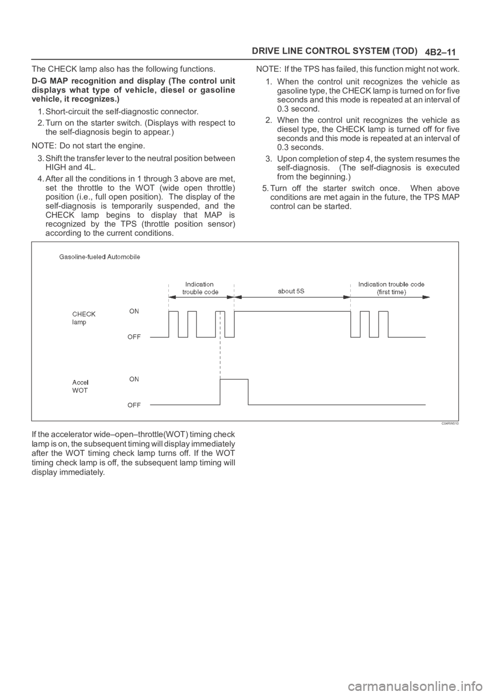
The CHECK lamp also has the following functions.
D-G MAP recognition and display (The control unit
displays what type of vehicle, diesel or gasoline
vehicle, it recognizes.)
1. Short-circuit the self-diagnostic connector.
2. Turn on the starter switch. (Displays with respect to
the self-diagnosis begin to appear.)
NOTE: Do not start the engine.
3. Shift the transfer lever to the neutral position between
HIGH and 4L.
4. After all the conditions in 1 through 3 above are met,
set the throttle to the WOT (wide open throttle)
position (i.e., full open position). The display of the
self-diagnosis is temporarily suspended, and the
CHECK lamp begins to display that MAP is
recognized by the TPS (throttle position sensor)
according to the current conditions.NOTE: If the TPS has failed, this function might not work.
1. When the control unit recognizes the vehicle as
gasoline type, the CHECK lamp is turned on for five
seconds and this mode is repeated at an interval of
0.3 second.
2. When the control unit recognizes the vehicle as
diesel type, the CHECK lamp is turned off for five
seconds and this mode is repeated at an interval of
0.3 seconds.
3. Upon completion of step 4, the system resumes the
self-diagnosis. (The self-diagnosis is executed
from the beginning.)
5. Turn off the starter switch once. When above
conditions are met again in the future, the TPS MAP
control can be started.
C04RW010
If the accelerator wide–open–throttle(WOT) timing check
lamp is on, the subsequent timing will display immediately
after the WOT timing check lamp turns off. If the WOT
timing check lamp is off, the subsequent lamp timing will
display immediately.