Page 3728 of 6000
LED on
LED off Indication for presence of a trouble Indication for normal state
0.5 0.5 0.5
3 second interval
Display pattern
ON
OFFNormal pattern
In car sensor
Ambient sensor
Sun sensor
Duct sensor
Mix actuatorFailed part
F01RX011
F01RY00007
FAN
MIX
MODE
DOOR
INTAKE
DOOR
SET UP
TEMPERATURE
100
(%)
33.5
F/H
VENT
B/L
FOOT
D/F
DEF
REC
MIX
FRE
F/C202122232425 2627282930F/H (%)
F/C
F01RY00001
Page 3729 of 6000
Independent check of sensors
Replace the control unit.
Sensors Allowable range Check method
In car sensor
Ambient sensor
Sun sensorRefer to the sensor resistance curve.
Refer to the sensor resistance curve.
100 ohms maximum in forward and 0.02 mA
minimum when exposed to 60W incandescent lamp.Chart 1
Chart 2
Chart 3
Replace the harness and
connector.
Replace the sensors.
Check the related harness and
connector
Normal ?
Normal ?NONO YES
YES
F01RY00005
Page 3730 of 6000
I-33I-34
0.3 BR/B
0.5 B/L
111
In car Sensor Auto A/C Control Unit
(In car Sensor)
(Sensor GND)4 3
I-33I-34
D08RY00174
Page 3731 of 6000
I-33C-86
H-24
0.3 LG/B
0.3 B/L
112
Ambient Sensor Auto A/C Control Unit
(Ambient Sensor)
(Sensor GND)I-330.3 LG/B
0.3 B/LH-24 8
H-24 9
C-86 1
C-86 2
D08RY00176
Page 3732 of 6000
0.3 LG/W
0.3 B/L
113
Sun Sensor Auto A/C Control Unit
(Sun Sensor)
(Sensor GND)I-33I-351
I-352
I-33I-35
D08RY00177
Page 3747 of 6000
I-32
C-1C-3I-33
E-3E-19B-19C-25
A 2
B-361
H-14
C-19
25A
BLOWER
MOTOR
C-20
10A
A/C FL-1
80A
MAIN
Heater
Relay
1B-3610
H-13
0.3
B 0.85
W/G0.85
W/R
3.0
W
3.0
L/R
0.5
BR
1.25
B
B-19
BODY-LH3
B-36
4B-36
BATT.(+)
Blower
MotorIntake
Actuator STARTER
RELAY(1)
0.5
LG 0.5
BR0.5
BR
0.5
G/W
0.5
P/G0.5
P/G0.5
G/O
0.5
G/O
PCM
(C3-E15)
31 13
COMP-F/B 70.5
BR
0.5
BR/Y 0.3
G/B0.5
G/B0.5
BR/Y 0.5
BR
Triple
Pressure
Switch
0.5
BR
A
A/C
Thermo Relay
Auto A/C Control Unit
3X-5
16
H-1617H-16
14
I-3218I-33
1X-5
13H-24
12
H-41
2 1
C-25
C-25
4X-5X-5 2
X-57
H-16
A/C
Compressor
Relay
Magnetic
clutch
1X-7
3X-74X-72
X-7
PCM
(C-1-B14)
E-39
1
H-67
H-41
5
H-41
Engine
Coolant
Temperature
Sensor
ENGINE COOLANT
TEMPERATURE GAUGE
0.5
Y/B
0.5
Y/B
0.5
Y/B
E-1911
1
H-61
H-24
I-334
B-36X-5X-7
H-14H-16
H-24
H-13
H-6H-41
6H-41
D08RY00182
Page 3753 of 6000
Temperature on the Sensor
Temperature Detector(¡C)
Sensor Resistance
Value(k‰)
20
25
30AU
T
O
4321
-20 0 5 10 15 20
25 30
-10 0 10 20 30 40
17.09
9.93
3.75
2.24
6.0
1.6 30.69
865RX007
‰
0
10 0 -10 -20 30 4020 5 10 15 20 25 30
Temperature on the Sensor
Temperature Detector(¡C)
Sensor Resistance
Value(k‰)
17.09 30.69
9.93
6.0
3.75
2.24
1.6
C01RX012
— Testing rod12
A
Current
value
40 A or more
+
12
21
D06RY00001
Page 3946 of 6000

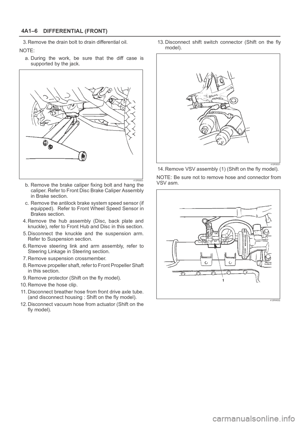
DIFFERENTIAL (FRONT) 4A1–6
3. Remove the drain bolt to drain differential oil.
NOTE:
a. During the work, be sure that the diff case is
supported by the jack.
412RS003
b. Remove the brake caliper fixing bolt and hang the
caliper. Refer to Front Disc Brake Caliper Assembly
in Brake section.
c. Remove the antilock brake system speed sensor (if
equipped). Refer to Front Wheel Speed Sensor in
Brakes section.
4. Remove the hub assembly (Disc, back plate and
knuckle), refer to Front Hub and Disc in this section.
5. Disconnect the knuckle and the suspension arm.
Refer to Suspension section.
6. Remove steering link and arm assembly, refer to
Steering Linkage in Steering section.
7. Remove suspension crossmember.
8. Remove propeller shaft, refer to Front Propeller Shaft
in this section.
9. Remove protector (Shift on the fly model).
10. Remove the hose clip.
11. Disconnect breather hose from front drive axle tube.
(and disconnect housing : Shift on the fly model).
12. Disconnect vacuum hose from actuator (Shift on the
fly model).13. Disconnect shift switch connector (Shift on the fly
model).
412RS031
14. Remove VSV assembly (1) (Shift on the fly model).
NOTE: Be sure not to remove hose and connector from
VSV asm.
412RW002