1998 OPEL FRONTERA sensor
[x] Cancel search: sensorPage 3133 of 6000
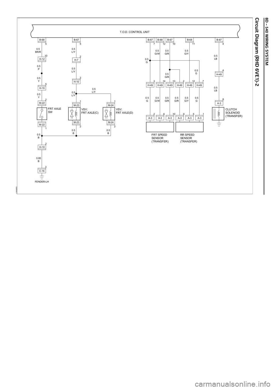
D08RW611
FRT AXLE
SW T.O.D. CONTROL UNIT
3C-16
FENDER-LH
M-22 0.5
L/Y
0.5 G 0.5
G/W 0.5
G/R 0.5
G/Y 0.5
LB
0.5
G/R 0.5
G
0.5 G 0.5
G
0.5
G/W 0.5
G/R 0.5
G/R 0.5
G/Y 0.5
LB
0.5
L/Y
0.5
L/Y
0.5
BR/R
0.5 P
0.5 Y
0.5 Y
0.5 B 0.5
B
0.5
B
0.85 B 0.5
L/Y
2
M-22 5
H-10
1 22
B-68
5
H-12 10
H-10
2
M-23 1
M-23 3
H-10
B-67
5
H-7 2
FRT SPEED
SENSOR
(TRANSFER) RR SPEED
SENSOR
(TRANSFER) CLUTCH
SOLENOID
(TRANSFER)
M-24 1
M-24
2A-3 3
H-49
B-67
7
6A-3 14
H-49
B-68
12
10A-3 13
H-49
2H-49 7H-49
B-67
10
5A-3
9A-3 1A-3
12
H-49
B-68
11
8A-3
H-49
B-67 4
4
VSV;
FRT AXLE(C) VSV;
FRT AXLE(D)
Page 3134 of 6000
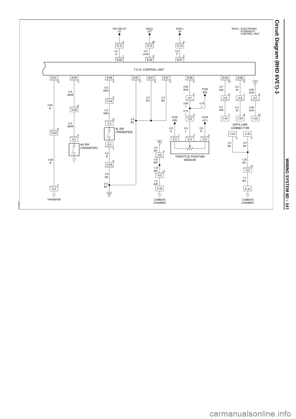
D08RW612
4H SW
(TRANSFER) T.O.D. CONTROL UNIT
7A-3
TRANSFER 9
H-49
A-3
0.5
B/L
0.85
B 4A-3 6
H-49
5
H-49
3
H-49 8
B-67
0.85 B 0.5
GR/R 0.5
GR/L
0.5
GR/L
0.5 B
0.5
B/L
0.5
GR/R
12B-68
3B-68 4B-6711B-67 6
4L SW
(TRANSFER)
12A-3
H-8 4
13
H-5
E-30
1.25
B/L
1.0
B/L E-29
3E-5 2E-5
14
H-5
5
H-6
COMMON
CHAMBER
COMMON
CHAMBER
B-68
9
H-7 6
C-63
C-63C-63
B-68
10
H-8
7
C-63
B-68 8
H-8
8
54
C-63
H-7 16
819
B
B
A B-67
9
0.5
B/L 0.5
B/L 0.5
B/L 0.85
R/W
0.85 L
0.75 L
0.8 L 0.8
R
0.8
G
0.5
B/L
0.5
B/P 0.5
B/L 0.5
B/L
0.5
O/B 0.3
W
0.3 W 0.85
G/W 0.85
G/W
0.5
O/B
1.25 B/P
1.0
B/R 0.75
L PCM
(E8)
PCM (A1)
PCM
(D8)
6B-68
EHCU
(27)
1E-5
THROTTLE POSITION
SENSOR DATA LINK
CONNECTOR
20H-15
1
B-68
TAIL RELAY
(3)
3H-15
0.3 G 0.5
LG/R 0.5
P 3
B-67
EHCU
(9) EHCU : ELECTRONIC
HYDRAULIC
CONTROL UNIT
9H-15
Page 3178 of 6000
METER AND GAUGE8E–1
METER AND GAUGE
CONTENTS
Service Precaution 8E–1. . . . . . . . . . . . . . . . . . . . . .
General Description 8E–1. . . . . . . . . . . . . . . . . . . . .
Meter Assembly 8E–2. . . . . . . . . . . . . . . . . . . . . . . . .
General Description 8E–2. . . . . . . . . . . . . . . . . . . . .
Layout for Meters/Gauges, Warning Lights,
Indicator Lights and Illumination Lights 8E–2. . .
Table for Meter/Gauge Connector Terminal
Connections 8E–8. . . . . . . . . . . . . . . . . . . . . . . . . .
Removal 8E–14. . . . . . . . . . . . . . . . . . . . . . . . . . . . .
Installation 8E–14. . . . . . . . . . . . . . . . . . . . . . . . . . . .
Warning Light Bulb, Indicator Light Bulb,
Illumination Light Bulb, A/T Indicator
Light Bulb 8E–14. . . . . . . . . . . . . . . . . . . . . . . . . . . . . .
Removal 8E–14. . . . . . . . . . . . . . . . . . . . . . . . . . . . .
Installation 8E–14. . . . . . . . . . . . . . . . . . . . . . . . . . . . Vehicle Speed Sensor 8E–15. . . . . . . . . . . . . . . . . . .
Removal 8E–15. . . . . . . . . . . . . . . . . . . . . . . . . . . . .
Installation 8E–15. . . . . . . . . . . . . . . . . . . . . . . . . . . .
Fuel Tank Unit 8E–15. . . . . . . . . . . . . . . . . . . . . . . . . .
Removal 8E–15. . . . . . . . . . . . . . . . . . . . . . . . . . . . .
Installation 8E–15. . . . . . . . . . . . . . . . . . . . . . . . . . . .
Multi Meter 8E–16. . . . . . . . . . . . . . . . . . . . . . . . . . . . .
Removal 8E–16. . . . . . . . . . . . . . . . . . . . . . . . . . . . .
Installation 8E–16. . . . . . . . . . . . . . . . . . . . . . . . . . . .
Ambient Sensor 8E–16. . . . . . . . . . . . . . . . . . . . . . . . .
Removal 8E–16. . . . . . . . . . . . . . . . . . . . . . . . . . . . .
Installation 8E–16. . . . . . . . . . . . . . . . . . . . . . . . . . . .
Main Data and Specifications 8E–17. . . . . . . . . . . . .
Service Precaution
WARNING: IF SO EQUIPPED WITH A
SUPPLEMENTAL RESTRAINT SYSTEM (SRS),
REFER TO THE SRS COMPONENT AND WIRING
LOCATION VIEW IN ORDER TO DETERMINE
WHETHER YOU ARE PERFORMING SERVICE ON OR
NEAR THE SRS COMPONENTS OR THE SRS
WIRING. WHEN YOU ARE PERFORMING SERVICE
ON OR NEAR THE SRS COMPONENTS OR THE SRS
WIRING, REFER TO THE SRS SERVICE
INFORMATION. FAILURE TO FOLLOW WARNINGS
COULD RESULT IN POSSIBLE AIR BAG
DEPLOYMENT, PERSONAL INJURY, OR
OTHERWISE UNNEEDED SRS SYSTEM REPAIRS.
CAUTION: Always use the correct fastener in the
proper location. When you replace a fastener, use
ONLY the exact part number for that application.
ISUZU will call out those fasteners that require a
replacement after removal. ISUZU will also call out
the fasteners that require thread lockers or thread
sealant. UNLESS OTHERWISE SPECIFIED, do not
use supplemental coatings (Paints, greases, or other
corrosion inhibitors) on threaded fasteners or
fastener joint interfaces. Generally, such coatings
adversely affect the fastener torque and the joint
clamping force, and may damage the fastener. When
you install fasteners, use the correct tightening
sequence and specifications. Following these
instructions can help you avoid damage to parts and
systems.
General Description
The circuit consists of the starter switch, meter assembly,
vehicle speed sensor, transmission switch, lighting
switch, turn signal switch, thermo unit, oil pressure unit,
Powertrain Control Module (PCM), fuel tank unit, 4WD
switch, oil pressure switch, parking brake switch, brake
fluid switch, seat belt switch, illumination controller, multi
meter and ambient sensor.
Page 3192 of 6000
METER AND GAUGE8E–15
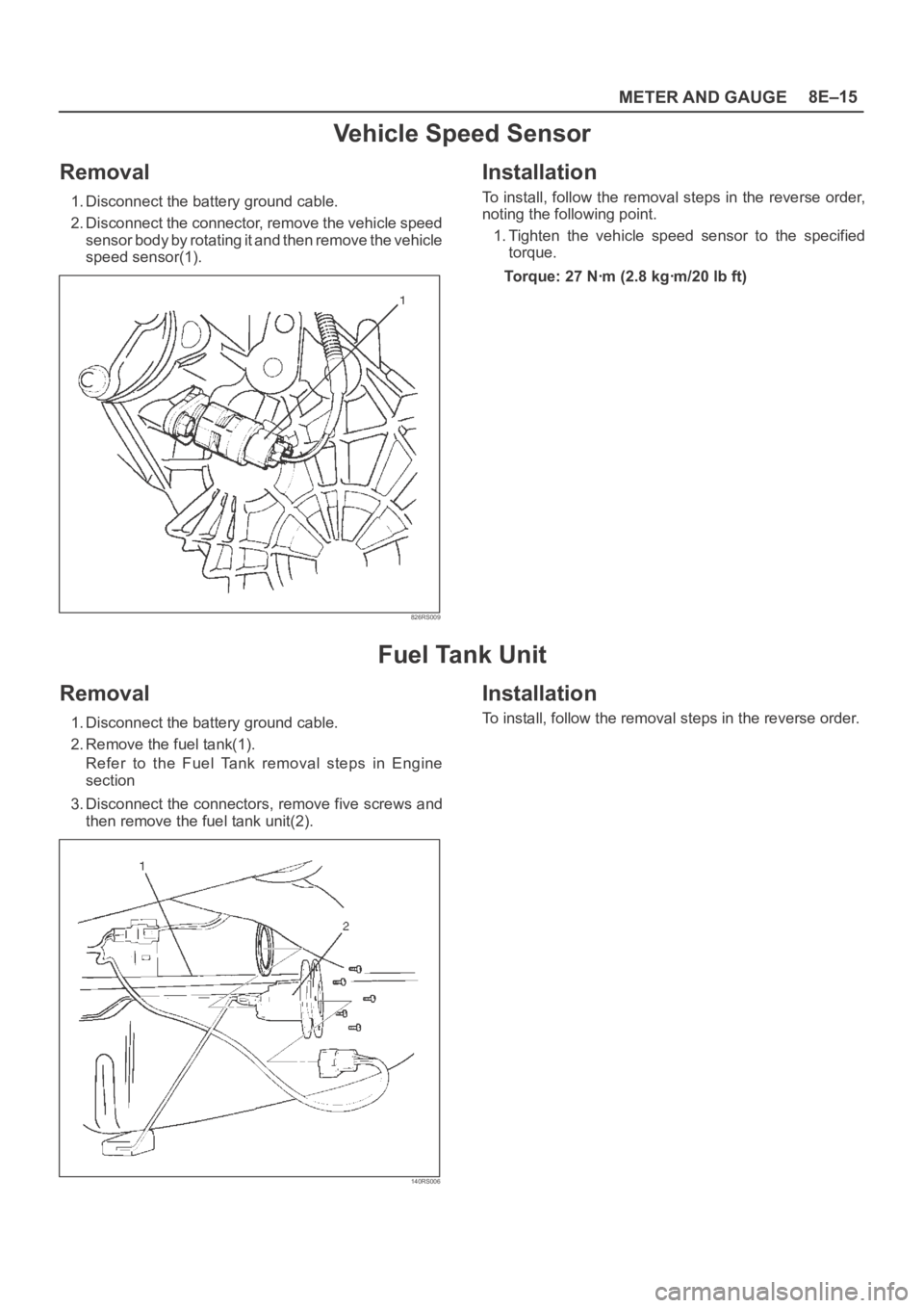
Vehicle Speed Sensor
Removal
1. Disconnect the battery ground cable.
2. Disconnect the connector, remove the vehicle speed
sensor body by rotating it and then remove the vehicle
speed sensor(1).
826RS009
Installation
To install, follow the removal steps in the reverse order,
noting the following point.
1. Tighten the vehicle speed sensor to the specified
torque.
Torque: 27 Nꞏm (2.8 kgꞏm/20 lb ft)
Fuel Tank Unit
Removal
1. Disconnect the battery ground cable.
2. Remove the fuel tank(1).
Refer to the Fuel Tank removal steps in Engine
section
3. Disconnect the connectors, remove five screws and
then remove the fuel tank unit(2).
140RS006
Installation
To install, follow the removal steps in the reverse order.
Page 3193 of 6000
8E–16METER AND GAUGE
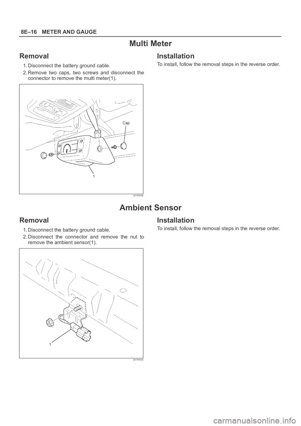
Multi Meter
Removal
1. Disconnect the battery ground cable.
2. Remove two caps, two screws and disconnect the
connector to remove the multi meter(1).
821RW036
Installation
To install, follow the removal steps in the reverse order.
Ambient Sensor
Removal
1. Disconnect the battery ground cable.
2. Disconnect the connector and remove the nut to
remove the ambient sensor(1).
821RW035
Installation
To install, follow the removal steps in the reverse order.
Page 3194 of 6000
METER AND GAUGE8E–17
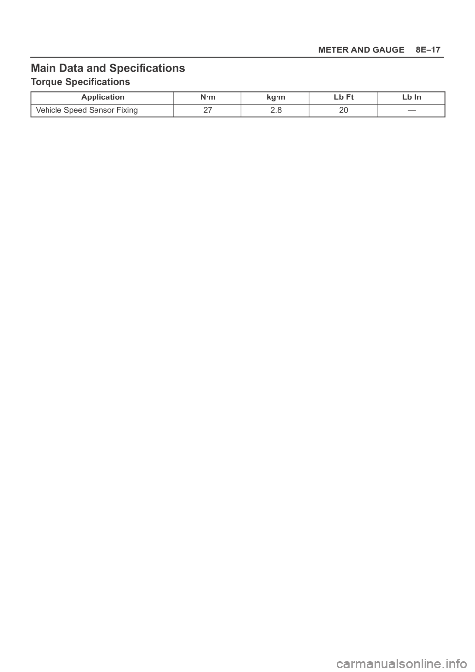
Main Data and Specifications
Torque Specifications
ApplicationNꞏmkgꞏmLb FtLb In
Vehicle Speed Sensor Fixing272.820—
Page 3446 of 6000
SUPPLEMENTAL RESTRAINT SYSTEM9J–9
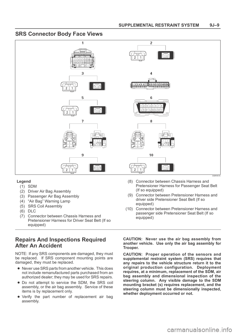
SRS Connector Body Face Views
D09RW016
Legend
(1) SDM
(2) Driver Air Bag Assembly
(3) Passenger Air Bag Assembly
(4) “Air Bag” Warning Lamp
(5) SRS Coil Assembly
(6) DLC
(7) Connector between Chassis Harness and
Pretensioner Harness for Driver Seat Belt (If so
equipped)(8) Connector between Chassis Harness and
Pretensioner Harness for Passenger Seat Belt
(If so equipped)
(9) Connector between Pretensioner Harness and
driver side Pretensioner Seat Belt (If so
equipped)
(10) Connector between Pretensioner Harness and
passenger side Pretensioner Seat Belt (If so
equipped)
Repairs And Inspections Required
After An Accident
NOTE: If any SRS components are damaged, they must
be replaced. If SRS component mounting points are
damaged, they must be replaced.
Never use SRS parts from another vehicle. This does
not include remanufactured parts purchased from an
a u t h o r i z e d d e a l e r ; t h e y m a y b e u s e d f o r S R S r e p a i r s .
Do not attempt to service the SDM, the SRS coil
assembly, or the air bag assembly. Service of these
items is by replacement only.
Verify the part number of replacement air bag
assembly.CAUTION: Never use the air bag assembly from
another vehicle. Use only the air bag assembly for
Trooper.
CAUTION: Proper operation of the sensors and
supplemental restraint system (SRS) requires that
any repairs to the vehicle structure return it to the
original production configuration. Deployment
requires, at a minimum, replacement of the SDM, air
bag assembly and dimensional inspection of the
steering column. Any visible damage to the SDM
mounting bracket (s) requires replacement, and the
steering column must be dimensionally inspected,
whether deployment occurred or not.
Page 3448 of 6000
SUPPLEMENTAL RESTRAINT SYSTEM9J–11
Handling / Installation / Diagnosis
1. Air bag assembly should not be subjected to
temperatures above 93
C (200F).
2. Air bag assembly, and SDM should not be used if they
have been dropped from a height of 100 centimeters
(3.28 feet) or more.
3. When a SDM is replaced, it must be oriented with the
arrow on the sensor pointing toward the front of the
vehicle. It is very important for the SDM to be located
flat on the mounting surface, parallel to the vehicle
datum line. It is important that the SDM mounting
surface is free of any dirt or other foreign material.
4. Do not apply power to the SRS unless all components
are connected or a diagnostic chart requests it, as this
will set a diagnostic trouble code.
5. The “SRS Diagnostic System Check” must be the
starting point of any SRS diagnostics. The “SRS
Diagnostic System Check” will verify proper “AIR
BAG” warning lamp operation and will lead you to the
correct chart to diagnose any SRS malfunctions.
Bypassing these procedures may result in extended
diagnostic time, incorrect diagnosis, and incorrect
parts replacement.
Air Bag Assembly Handling /
Shipping / Scrapping
Live (Undeployed) Air Bag Assembly
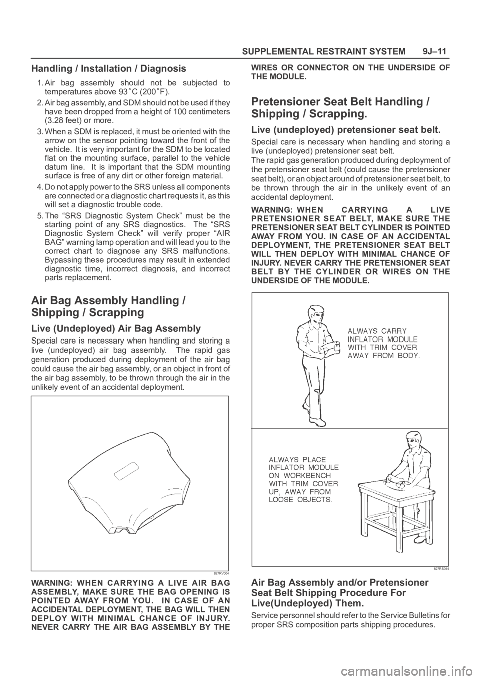
Special care is necessary when handling and storing a
live (undeployed) air bag assembly. The rapid gas
generation produced during deployment of the air bag
could cause the air bag assembly, or an object in front of
the air bag assembly, to be thrown through the air in the
unlikely event of an accidental deployment.
827RV004
WARNING: WHEN CARRYING A LIVE AIR BAG
ASSEMBLY, MAKE SURE THE BAG OPENING IS
POINTED AWAY FROM YOU. IN CASE OF AN
ACCIDENTAL DEPLOYMENT, THE BAG WILL THEN
DEPLOY WITH MINIMAL CHANCE OF INJURY.
NEVER CARRY THE AIR BAG ASSEMBLY BY THEWIRES OR CONNECTOR ON THE UNDERSIDE OF
THE MODULE.
Pretensioner Seat Belt Handling /
Shipping / Scrapping.
Live (undeployed) pretensioner seat belt.
Special care is necessary when handling and storing a
live (undeployed) pretensioner seat belt.
The rapid gas generation produced during deployment of
the pretensioner seat belt (could cause the pretensioner
seat belt), or an object around of pretensioner seat belt, to
be thrown through the air in the unlikely event of an
accidental deployment.
WARNING: WHEN CARRYING A LIVE
PRETENSIONER SEAT BELT, MAKE SURE THE
PRETENSIONER SEAT BELT CYLINDER IS POINTED
AWAY FROM YOU. IN CASE OF AN ACCIDENTAL
DEPLOYMENT, THE PRETENSIONER SEAT BELT
WILL THEN DEPLOY WITH MINIMAL CHANCE OF
INJURY. NEVER CARRY THE PRETENSIONER SEAT
BELT BY THE CYLINDER OR WIRES ON THE
UNDERSIDE OF THE MODULE.
827RS044
Air Bag Assembly and/or Pretensioner
Seat Belt Shipping Procedure For
Live(Undeployed) Them.
Service personnel should refer to the Service Bulletins for
proper SRS composition parts shipping procedures.