1998 OPEL FRONTERA fuel
[x] Cancel search: fuelPage 5616 of 6000
6E–187 4JX1–TC ENGINE DRIVEABILITY AND EMISSIONS
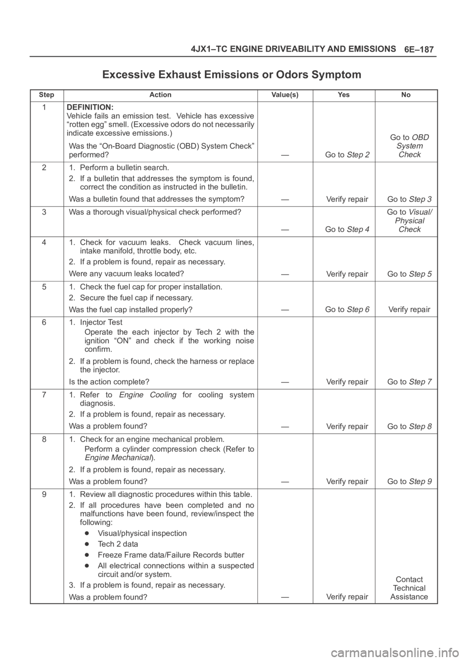
Excessive Exhaust Emissions or Odors Symptom
StepActionVa l u e ( s )Ye sNo
1DEFINITION:
Vehicle fails an emission test. Vehicle has excessive
“rotten egg” smell. (Excessive odors do not necessarily
indicate excessive emissions.)
Was the “On-Board Diagnostic (OBD) System Check”
performed?
—Go to Step 2
Go to OBD
System
Check
21. Perform a bulletin search.
2. If a bulletin that addresses the symptom is found,
correct the condition as instructed in the bulletin.
Was a bulletin found that addresses the symptom?
—Verify repairGo to Step 3
3Was a thorough visual/physical check performed?
—Go to Step 4
Go to Visual/
Physical
Check
41. Check for vacuum leaks. Check vacuum lines,
intake manifold, throttle body, etc.
2. If a problem is found, repair as necessary.
Were any vacuum leaks located?
—Verify repairGo to Step 5
51. Check the fuel cap for proper installation.
2. Secure the fuel cap if necessary.
Was the fuel cap installed properly?
—Go to Step 6Verify repair
61. Injector Test
Operate the each injector by Tech 2 with the
ignition “ON” and check if the working noise
confirm.
2. If a problem is found, check the harness or replace
the injector.
Is the action complete?
—Verify repairGo to Step 7
71. Refer to Engine Cooling for cooling system
diagnosis.
2. If a problem is found, repair as necessary.
Was a problem found?
—Verify repairGo to Step 8
81. Check for an engine mechanical problem.
Perform a cylinder compression check (Refer to
Engine Mechanical).
2. If a problem is found, repair as necessary.
Was a problem found?
—Verify repairGo to Step 9
91. Review all diagnostic procedures within this table.
2. If all procedures have been completed and no
malfunctions have been found, review/inspect the
following:
Visual/physical inspection
Te c h 2 d a t a
Freeze Frame data/Failure Records butter
All electrical connections within a suspected
circuit and/or system.
3. If a problem is found, repair as necessary.
Was a problem found?
—Verify repair
Contact
Te c h n i c a l
Assistance
Page 5621 of 6000
6E–192
4JX1–TC ENGINE DRIVEABILITY AND EMISSIONS
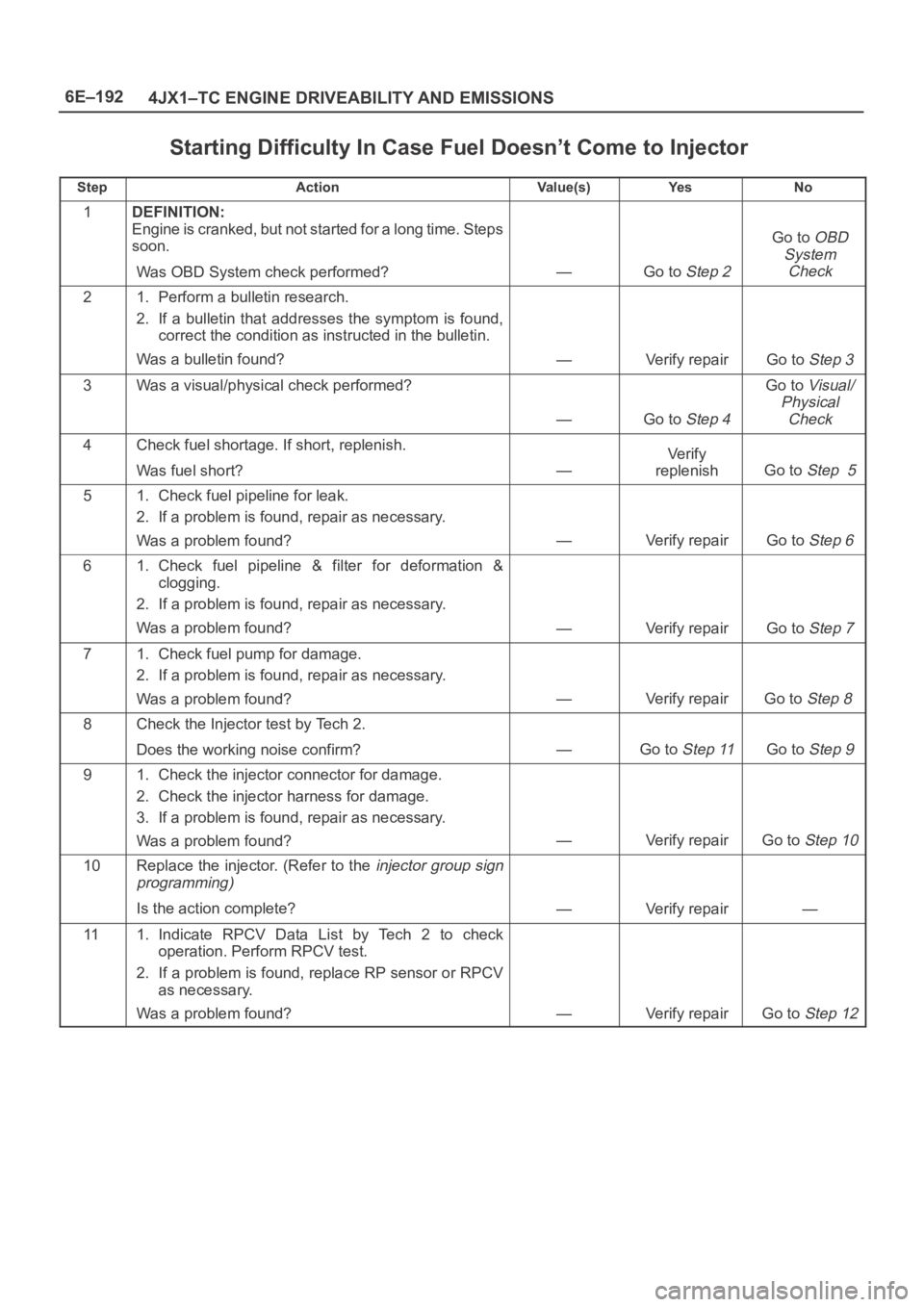
Starting Difficulty In Case Fuel Doesn’t Come to Injector
StepActionVa l u e ( s )Ye sNo
1DEFINITION:
Engine is cranked, but not started for a long time. Steps
soon.
Was OBD System check performed?
—Go to Step 2
Go to OBD
System
Check
21. Perform a bulletin research.
2. If a bulletin that addresses the symptom is found,
correct the condition as instructed in the bulletin.
Was a bulletin found?
—Verify repairGo to Step 3
3Was a visual/physical check performed?
—Go to Step 4
Go to Visual/
Physical
Check
4Check fuel shortage. If short, replenish.
Was fuel short?
—
Ve r i f y
replenish
Go to Step 5
51. Check fuel pipeline for leak.
2. If a problem is found, repair as necessary.
Was a problem found?
—Verify repairGo to Step 6
61. Check fuel pipeline & filter for deformation &
clogging.
2. If a problem is found, repair as necessary.
Was a problem found?
—Verify repairGo to Step 7
71. Check fuel pump for damage.
2. If a problem is found, repair as necessary.
Was a problem found?
—Verify repairGo to Step 8
8Check the Injector test by Tech 2.
Does the working noise confirm?
—Go to Step 11Go to Step 9
91. Check the injector connector for damage.
2. Check the injector harness for damage.
3. If a problem is found, repair as necessary.
Was a problem found?
—Verify repairGo to Step 10
10Replace the injector. (Refer to the injector group sign
programming)
Is the action complete?—Verify repair—
111. Indicate RPCV Data List by Tech 2 to check
operation. Perform RPCV test.
2. If a problem is found, replace RP sensor or RPCV
as necessary.
Was a problem found?
—Verify repairGo to Step 12
Page 5622 of 6000
6E–193 4JX1–TC ENGINE DRIVEABILITY AND EMISSIONS
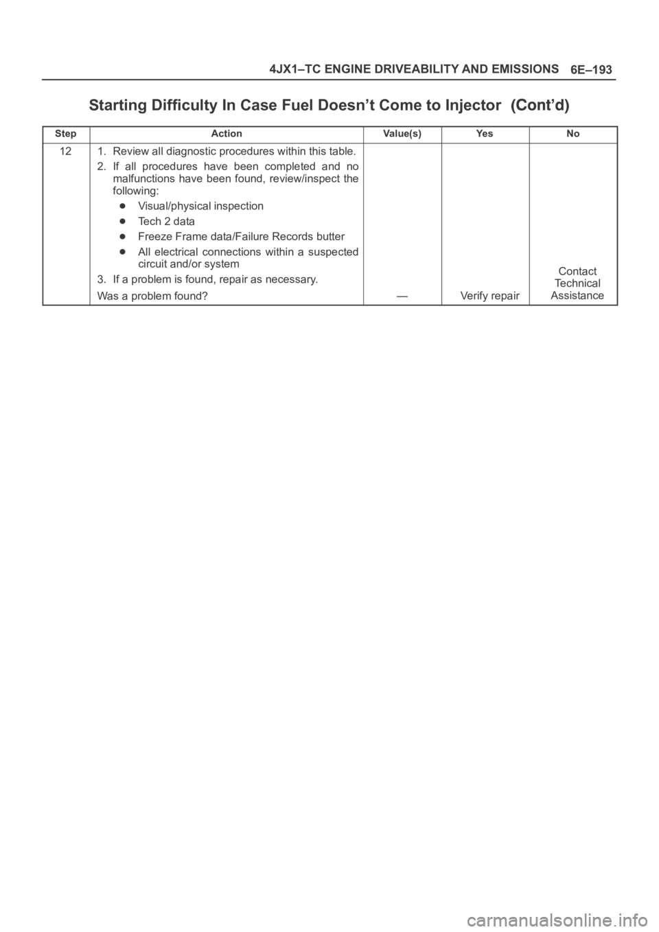
Starting Difficulty In Case Fuel Doesn’t Come to Injector
StepNo Ye s Va l u e ( s ) Action
121. Review all diagnostic procedures within this table.
2. If all procedures have been completed and no
malfunctions have been found, review/inspect the
following:
Visual/physical inspection
Te c h 2 d a t a
Freeze Frame data/Failure Records butter
All electrical connections within a suspected
circuit and/or system
3. If a problem is found, repair as necessary.
Was a problem found?
—Verify repair
Contact
Te c h n i c a l
Assistance
Page 5626 of 6000
6E–197 4JX1–TC ENGINE DRIVEABILITY AND EMISSIONS
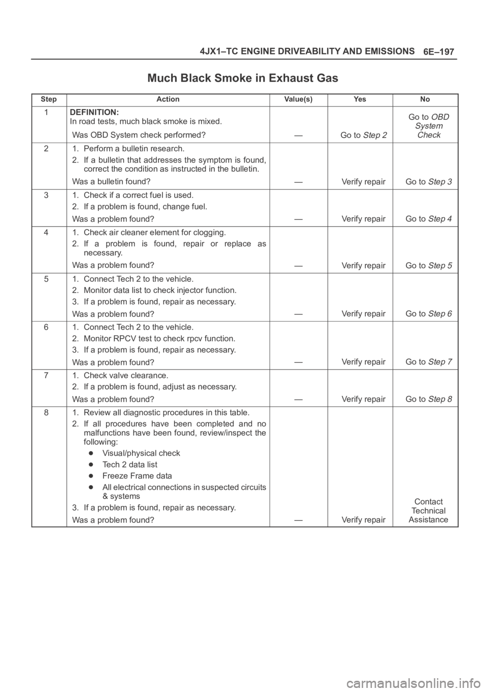
Much Black Smoke in Exhaust Gas
StepActionVa l u e ( s )Ye sNo
1DEFINITION:
In road tests, much black smoke is mixed.
Was OBD System check performed?
—Go to Step 2
Go to OBD
System
Check
21. Perform a bulletin research.
2. If a bulletin that addresses the symptom is found,
correct the condition as instructed in the bulletin.
Was a bulletin found?
—Verify repairGo to Step 3
31. Check if a correct fuel is used.
2. If a problem is found, change fuel.
Was a problem found?
—Verify repairGo to Step 4
41. Check air cleaner element for clogging.
2. If a problem is found, repair or replace as
necessary.
Was a problem found?
—Verify repairGo to Step 5
51. Connect Tech 2 to the vehicle.
2. Monitor data list to check injector function.
3. If a problem is found, repair as necessary.
Was a problem found?
—Verify repairGo to Step 6
61. Connect Tech 2 to the vehicle.
2. Monitor RPCV test to check rpcv function.
3. If a problem is found, repair as necessary.
Was a problem found?
—Verify repairGo to Step 7
71. Check valve clearance.
2. If a problem is found, adjust as necessary.
Was a problem found?
—Verify repairGo to Step 8
81. Review all diagnostic procedures in this table.
2. If all procedures have been completed and no
malfunctions have been found, review/inspect the
following:
Visual/physical check
Tech 2 data list
Freeze Frame data
All electrical connections in suspected circuits
& systems
3. If a problem is found, repair as necessary.
Was a problem found?
—Verify repair
Contact
Te c h n i c a l
Assistance
Page 5628 of 6000
6E–199 4JX1–TC ENGINE DRIVEABILITY AND EMISSIONS
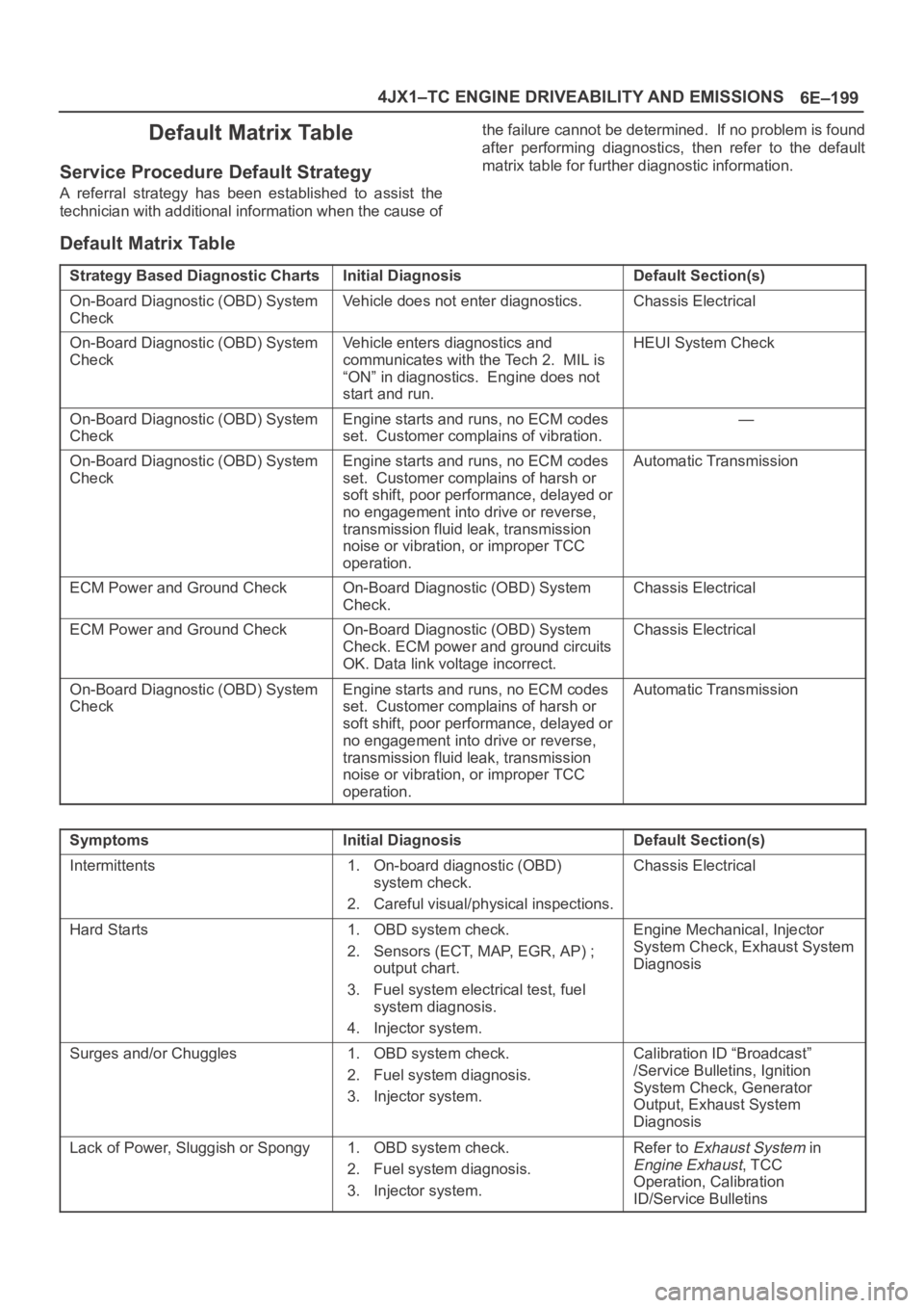
Default Matrix Table
Service Procedure Default Strategy
A referral strategy has been established to assist the
technician with additional information when the cause ofthe failure cannot be determined. If no problem is found
after performing diagnostics, then refer to the default
matrix table for further diagnostic information.
Default Matrix Table
Strategy Based Diagnostic ChartsInitial DiagnosisDefault Section(s)
On-Board Diagnostic (OBD) System
CheckVehicle does not enter diagnostics.Chassis Electrical
On-Board Diagnostic (OBD) System
CheckVehicle enters diagnostics and
communicates with the Tech 2. MIL is
“ON” in diagnostics. Engine does not
start and run.HEUI System Check
On-Board Diagnostic (OBD) System
CheckEngine starts and runs, no ECM codes
set. Customer complains of vibration.—
On-Board Diagnostic (OBD) System
CheckEngine starts and runs, no ECM codes
set. Customer complains of harsh or
soft shift, poor performance, delayed or
no engagement into drive or reverse,
transmission fluid leak, transmission
noise or vibration, or improper TCC
operation.Automatic Transmission
ECM Power and Ground CheckOn-Board Diagnostic (OBD) System
Check.Chassis Electrical
ECM Power and Ground CheckOn-Board Diagnostic (OBD) System
Check. ECM power and ground circuits
OK. Data link voltage incorrect.Chassis Electrical
On-Board Diagnostic (OBD) System
CheckEngine starts and runs, no ECM codes
set. Customer complains of harsh or
soft shift, poor performance, delayed or
no engagement into drive or reverse,
transmission fluid leak, transmission
noise or vibration, or improper TCC
operation.Automatic Transmission
SymptomsInitial DiagnosisDefault Section(s)
Intermittents1. On-board diagnostic (OBD)
system check.
2. Careful visual/physical inspections.Chassis Electrical
Hard Starts1. OBD system check.
2. Sensors (ECT, MAP, EGR, AP) ;
output chart.
3. Fuel system electrical test, fuel
system diagnosis.
4. Injector system.Engine Mechanical, Injector
System Check, Exhaust System
Diagnosis
Surges and/or Chuggles1. OBD system check.
2. Fuel system diagnosis.
3. Injector system.Calibration ID “Broadcast”
/Service Bulletins, Ignition
System Check, Generator
Output, Exhaust System
Diagnosis
Lack of Power, Sluggish or Spongy1. OBD system check.
2. Fuel system diagnosis.
3. Injector system.Refer to Exhaust System in
Engine Exhaust, TCC
Operation, Calibration
ID/Service Bulletins
Page 5629 of 6000
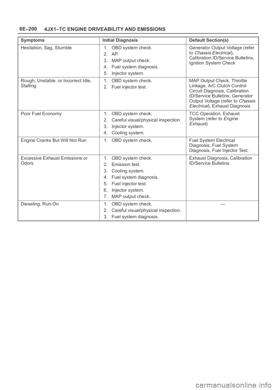
6E–200
4JX1–TC ENGINE DRIVEABILITY AND EMISSIONS
SymptomsInitial DiagnosisDefault Section(s)
Hesitation, Sag, Stumble1. OBD system check.
2. AP.
3. MAP output check.
4. Fuel system diagnosis.
5. Injector system.Generator Output Voltage (refer
to
Chassis Electrical),
Calibration ID/Service Bulletins,
Ignition System Check
Rough, Unstable, or Incorrect Idle,
Stalling1. OBD system check.
2. Fuel injector test.MAP Output Check, Throttle
Linkage, A/C Clutch Control
Circuit Diagnosis, Calibration
ID/Service Bulletins, Generator
Output Voltage (refer to
Chassis
Electrical
), Exhaust Diagnosis
Poor Fuel Economy1. OBD system check.
2. Careful visual/physical inspection.
3. Injector system.
4. Cooling system.TCC Operation, Exhaust
System (refer to
Engine
Exhaust
)
Engine Cranks But Will Not Run1. OBD system check.Fuel System Electrical
Diagnosis, Fuel System
Diagnosis, Fuel Injector Test.
Excessive Exhaust Emissions or
Odors1. OBD system check.
2. Emission test.
3. Cooling system.
4. Fuel system diagnosis.
5. Fuel injector test.
6. Injector system.
7. MAP output check.Exhaust Diagnosis, Calibration
ID/Service Bulletins
Dieseling, Run-On1. OBD system check.
2. Careful visual/physical inspection.
3. Fuel system diagnosis.—
Page 5632 of 6000
6E–203 4JX1–TC ENGINE DRIVEABILITY AND EMISSIONS
Engine Coolant Temperature
(ECT) Sensor
Removal Procedure
NOTE: Care must be taken when handling the engine
coolant temperature (ECT) sensor. Damage to the ECT
sensor will affect proper operation of the fuel injection
system.
1. Disconnect the negative battery cable.
2. Drain the radiator coolant. Refer to
Draining and
Refilling Cooling System
in Engine Cooling.
3. Disconnect the electrical connector.
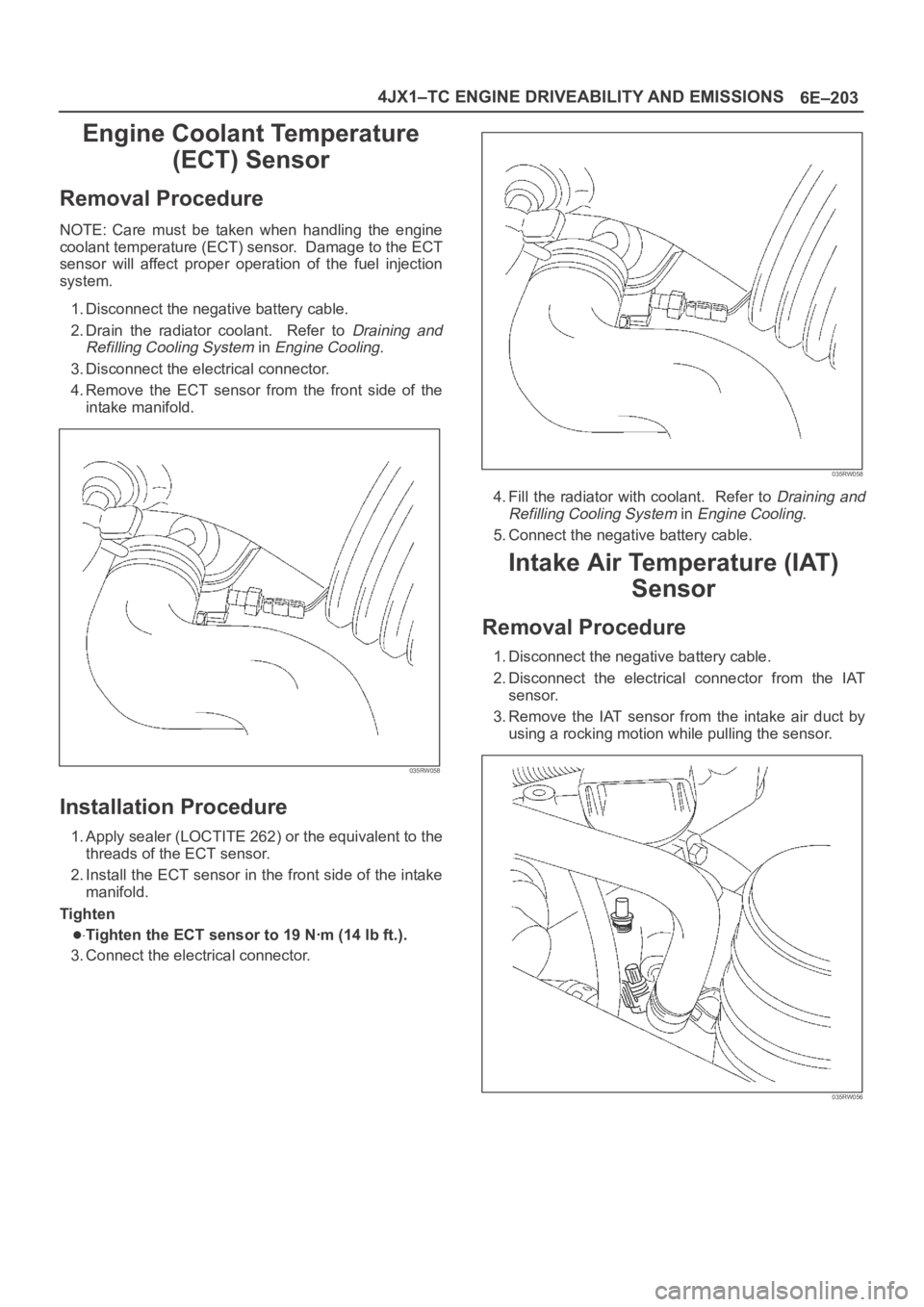
4.Remove the ECT sensor from the front side of the
intake manifold.
035RW058
Installation Procedure
1. Apply sealer (LOCTITE 262) or the equivalent to the
threads of the ECT sensor.
2. Install the ECT sensor in the front side of the intake
manifold.
Tighten
Tighten the ECT sensor to 19 Nꞏm (14 lb ft.).
3. Connect the electrical connector.
035RW058
4. Fill the radiator with coolant. Refer to Draining and
Refilling Cooling System
in Engine Cooling.
5. Connect the negative battery cable.
Intake Air Temperature (IAT)
Sensor
Removal Procedure
1. Disconnect the negative battery cable.
2. Disconnect the electrical connector from the IAT
sensor.
3. Remove the IAT sensor from the intake air duct by
using a rocking motion while pulling the sensor.
035RW056
Page 5642 of 6000
6E–213 4JX1–TC ENGINE DRIVEABILITY AND EMISSIONS
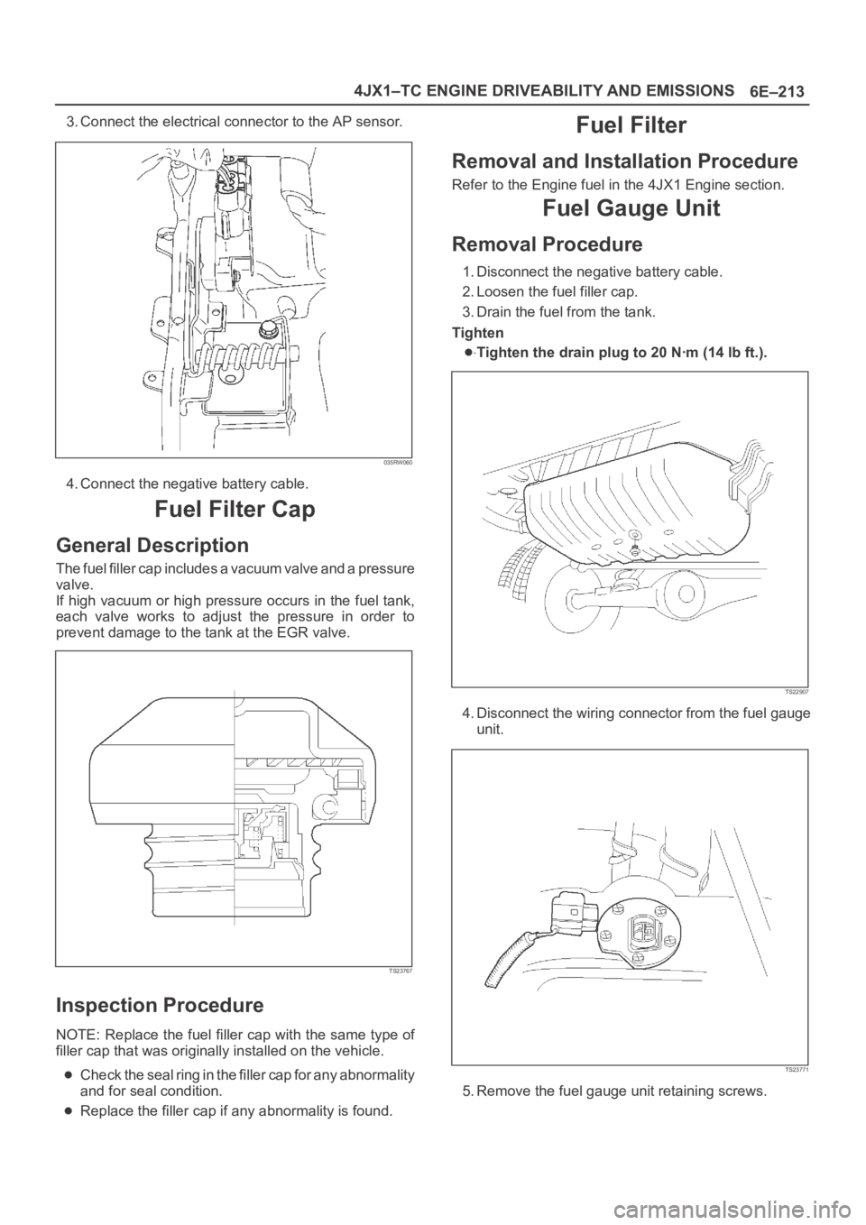
3. Connect the electrical connector to the AP sensor.
035RW060
4. Connect the negative battery cable.
Fuel Filter Cap
General Description
The fuel filler cap includes a vacuum valve and a pressure
valve.
If high vacuum or high pressure occurs in the fuel tank,
each valve works to adjust the pressure in order to
prevent damage to the tank at the EGR valve.
TS23767
Inspection Procedure
NOTE: Replace the fuel filler cap with the same type of
filler cap that was originally installed on the vehicle.
Check the seal ring in the filler cap for any abnormality
and for seal condition.
Replace the filler cap if any abnormality is found.
Fuel Filter
Removal and Installation Procedure
Refer to the Engine fuel in the 4JX1 Engine section.
Fuel Gauge Unit
Removal Procedure
1. Disconnect the negative battery cable.
2. Loosen the fuel filler cap.
3. Drain the fuel from the tank.
Tighten
Tighten the drain plug to 20 Nꞏm (14 lb ft.).
TS22907
4. Disconnect the wiring connector from the fuel gauge
unit.
TS23771
5. Remove the fuel gauge unit retaining screws.