1998 OPEL FRONTERA fuel
[x] Cancel search: fuelPage 5551 of 6000
6E–122
4JX1–TC ENGINE DRIVEABILITY AND EMISSIONS
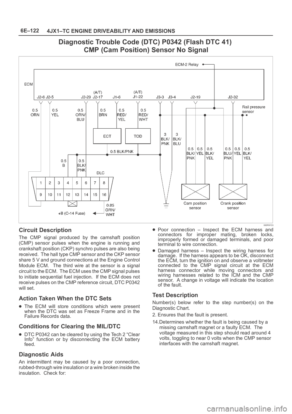
Diagnostic Trouble Code (DTC) P0342 (Flash DTC 41)
CMP (Cam Position) Sensor No Signal
060RW133
Circuit Description
The CMP signal produced by the camshaft position
(CMP) sensor pulses when the engine is running and
crankshaft position (CKP) synchro pulses are also being
received. The hall type CMP sensor and the CKP sensor
share 5 V and ground connections at the Engine Control
Module ECM. The third wire at the sensor is a signal
c i r c u i t t o t h e E C M . T h e E C M u s e s t h e C M P s i g n a l p u l s e s
to initiate sequential fuel injection. If the ECM does not
receive pulses on the CMP reference circuit, DTC P0342
will set.
Action Taken When the DTC Sets
The ECM will store conditions which were present
when the DTC was set as Freeze Frame and in the
Failure Records data.
Conditions for Clearing the MIL/DTC
DTC P0342 can be cleared by using the Tech 2 “Clear
Info” function or by disconnecting the ECM battery
feed.
Diagnostic Aids
An intermittent may be caused by a poor connection,
rubbed-through wire insulation or a wire broken inside the
insulation. Check for:
Poor connection – Inspect the ECM harness and
connectors for improper mating, broken locks,
improperly formed or damaged terminals, and poor
terminal to wire connection.
Damaged harness – Inspect the wiring harness for
damage. If the harness appears to be OK, disconnect
the ECM, turn the ignition on and observe a voltmeter
connected to the CMP signal circuit at the ECM
harness connector while moving connectors and
wiring harnesses related to the ICM and the CMP
sensor. A change in voltage will indicate the location
of the fault.
Test Description
Number(s) below refer to the step number(s) on the
Diagnostic Chart.
2. Ensures that the fault is present.
14.Determines whether the fault is being caused by a
missing camshaft magnet or a faulty ECM. The
voltage measured in this step should read around 4
volts, toggling to near 0 volts when the CMP sensor
interfaces with the camshaft magnet.
Page 5584 of 6000
6E–155 4JX1–TC ENGINE DRIVEABILITY AND EMISSIONS
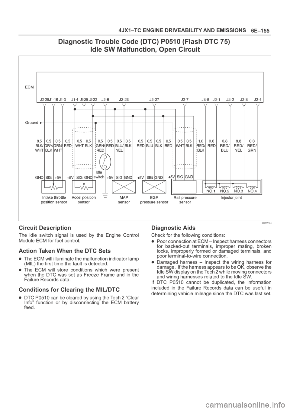
Diagnostic Trouble Code (DTC) P0510 (Flash DTC 75)
Idle SW Malfunction, Open Circuit
060RW134
Circuit Description
The idle switch signal is used by the Engine Control
Module ECM for fuel control.
Action Taken When the DTC Sets
The ECM will illuminate the malfunction indicator lamp
(MIL) the first time the fault is detected.
The ECM will store conditions which were present
when the DTC was set as Freeze Frame and in the
Failure Records data.
Conditions for Clearing the MIL/DTC
DTC P0510 can be cleared by using the Tech 2 “Clear
Info” function or by disconnecting the ECM battery
feed.
Diagnostic Aids
Check for the following conditions:
Poor connection at ECM – Inspect harness connectors
for backed-out terminals, improper mating, broken
locks, improperly formed or damaged terminals, and
poor terminal-to-wire connection.
Damaged harness – Inspect the wiring harness for
damage. If the harness appears to be OK, observe the
Idle SW display on the Tech 2 while moving connectors
and wiring harnesses related to the Idle SW.
If DTC P0510 cannot be duplicated, the information
included in the Failure Records data can be useful in
determining vehicle mileage since the DTC was last set.
Page 5586 of 6000
6E–157 4JX1–TC ENGINE DRIVEABILITY AND EMISSIONS
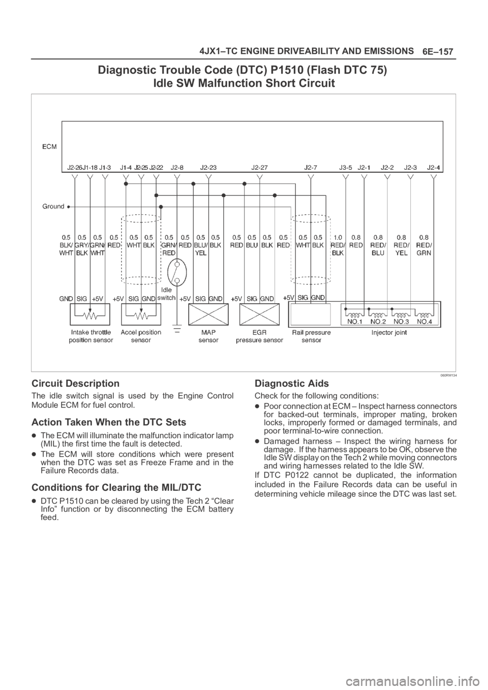
Diagnostic Trouble Code (DTC) P1510 (Flash DTC 75)
Idle SW Malfunction Short Circuit
060RW134
Circuit Description
The idle switch signal is used by the Engine Control
Module ECM for fuel control.
Action Taken When the DTC Sets
The ECM will illuminate the malfunction indicator lamp
(MIL) the first time the fault is detected.
The ECM will store conditions which were present
when the DTC was set as Freeze Frame and in the
Failure Records data.
Conditions for Clearing the MIL/DTC
DTC P1510 can be cleared by using the Tech 2 “Clear
Info” function or by disconnecting the ECM battery
feed.
Diagnostic Aids
Check for the following conditions:
Poor connection at ECM – Inspect harness connectors
for backed-out terminals, improper mating, broken
locks, improperly formed or damaged terminals, and
poor terminal-to-wire connection.
Damaged harness – Inspect the wiring harness for
damage. If the harness appears to be OK, observe the
Idle SW display on the Tech 2 while moving connectors
and wiring harnesses related to the Idle SW.
If DTC P0122 cannot be duplicated, the information
included in the Failure Records data can be useful in
determining vehicle mileage since the DTC was last set.
Page 5606 of 6000
6E–177 4JX1–TC ENGINE DRIVEABILITY AND EMISSIONS
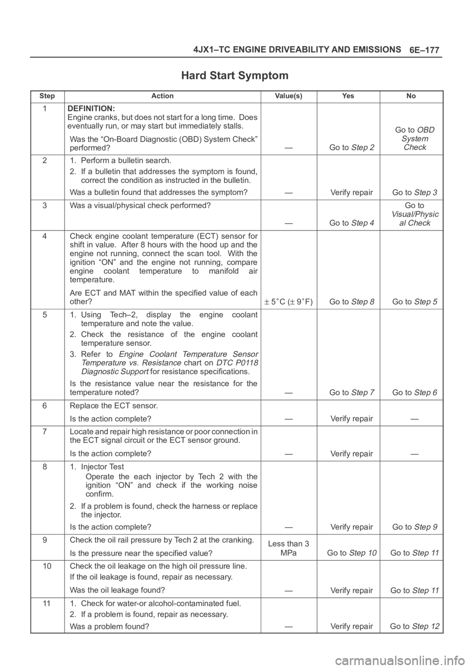
Hard Start Symptom
StepActionVa l u e ( s )Ye sNo
1DEFINITION:
Engine cranks, but does not start for a long time. Does
eventually run, or may start but immediately stalls.
Was the “On-Board Diagnostic (OBD) System Check”
performed?
—Go to Step 2
Go to OBD
System
Check
21. Perform a bulletin search.
2. If a bulletin that addresses the symptom is found,
correct the condition as instructed in the bulletin.
Was a bulletin found that addresses the symptom?
—Verify repairGo to Step 3
3Was a visual/physical check performed?
—Go to Step 4
Go to
Visual/Physic
al Check
4Check engine coolant temperature (ECT) sensor for
shift in value. After 8 hours with the hood up and the
engine not running, connect the scan tool. With the
ignition “ON” and the engine not running, compare
engine coolant temperature to manifold air
temperature.
Are ECT and MAT within the specified value of each
other?
5C ( 9F)Go to Step 8Go to Step 5
51. Using Tech–2, display the engine coolant
temperature and note the value.
2. Check the resistance of the engine coolant
temperature sensor.
3. Refer to
Engine Coolant Temperature Sensor
Temperature vs. Resistance
chart on DTC P0118
Diagnostic Support
for resistance specifications.
Is the resistance value near the resistance for the
temperature noted?
—Go to Step 7Go to Step 6
6Replace the ECT sensor.
Is the action complete?
—Verify repair—
7Locate and repair high resistance or poor connection in
the ECT signal circuit or the ECT sensor ground.
Is the action complete?
—Verify repair—
81. Injector Test
Operate the each injector by Tech 2 with the
ignition “ON” and check if the working noise
confirm.
2. If a problem is found, check the harness or replace
the injector.
Is the action complete?
—Verify repairGo to Step 9
9Check the oil rail pressure by Tech 2 at the cranking.
Is the pressure near the specified value?Less than 3
MPa
Go to Step 10Go to Step 11
10Check the oil leakage on the high oil pressure line.
If the oil leakage is found, repair as necessary.
Was the oil leakage found?
—Verify repairGo to Step 11
111. Check for water-or alcohol-contaminated fuel.
2. If a problem is found, repair as necessary.
Was a problem found?
—Verify repairGo to Step 12
Page 5608 of 6000
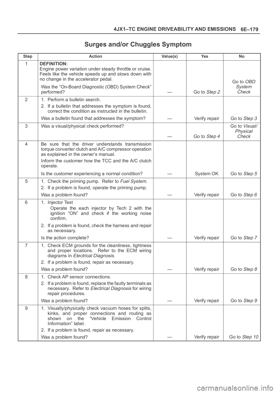
6E–179 4JX1–TC ENGINE DRIVEABILITY AND EMISSIONS
Surges and/or Chuggles Symptom
StepActionVa l u e ( s )Ye sNo
1DEFINITION:
Engine power variation under steady throttle or cruise.
Feels like the vehicle speeds up and slows down with
no change in the accelerator pedal.
Was the “On-Board Diagnostic (OBD) System Check”
performed?
—Go to Step 2
Go to OBD
System
Check
21. Perform a bulletin search.
2. If a bulletin that addresses the symptom is found,
correct the condition as instructed in the bulletin.
Was a bulletin found that addresses the symptom?
—Verify repairGo to Step 3
3Was a visual/physical check performed?
—Go to Step 4
Go to Visual/
Physical
Check
4Be sure that the driver understands transmission
torque converter clutch and A/C compressor operation
as explained in the owner’s manual.
Inform the customer how the TCC and the A/C clutch
operate.
Is the customer experiencing a normal condition?
—System OKGo to Step 5
51. Check the priming pump. Refer to Fuel System.
2. If a problem is found, operate the priming pump.
Was a problem found?
—Verify repairGo to Step 6
61. Injector Test
Operate the each injector by Tech 2 with the
ignition “ON” and check if the working noise
confirm.
2. If a problem is found, check the harness and repair
as necessary.
Is the action complete?
—Verify repairGo to Step 7
71. Check ECM grounds for the cleanliness, tightness
and proper locations. Refer to the ECM wiring
diagrams in
Electrical Diagnosis.
2. If a problem is found, repair as necessary.
Was a problem found?
—Verify repairGo to Step 8
81. Check AP sensor connections.
2. If a problem is found, replace the faulty terminals as
necessary. Refer to
Electrical Diagnosis for wiring
repair procedures.
Was a problem found?
—Verify repairGo to Step 9
91. Visually/physically check vacuum hoses for splits,
kinks, and proper connections and routing as
shown on the “Vehicle Emission Control
Information” label.
2. If a problem is found, repair as necessary.
Was a problem found?
—Verify repairGo to Step 10
Page 5610 of 6000
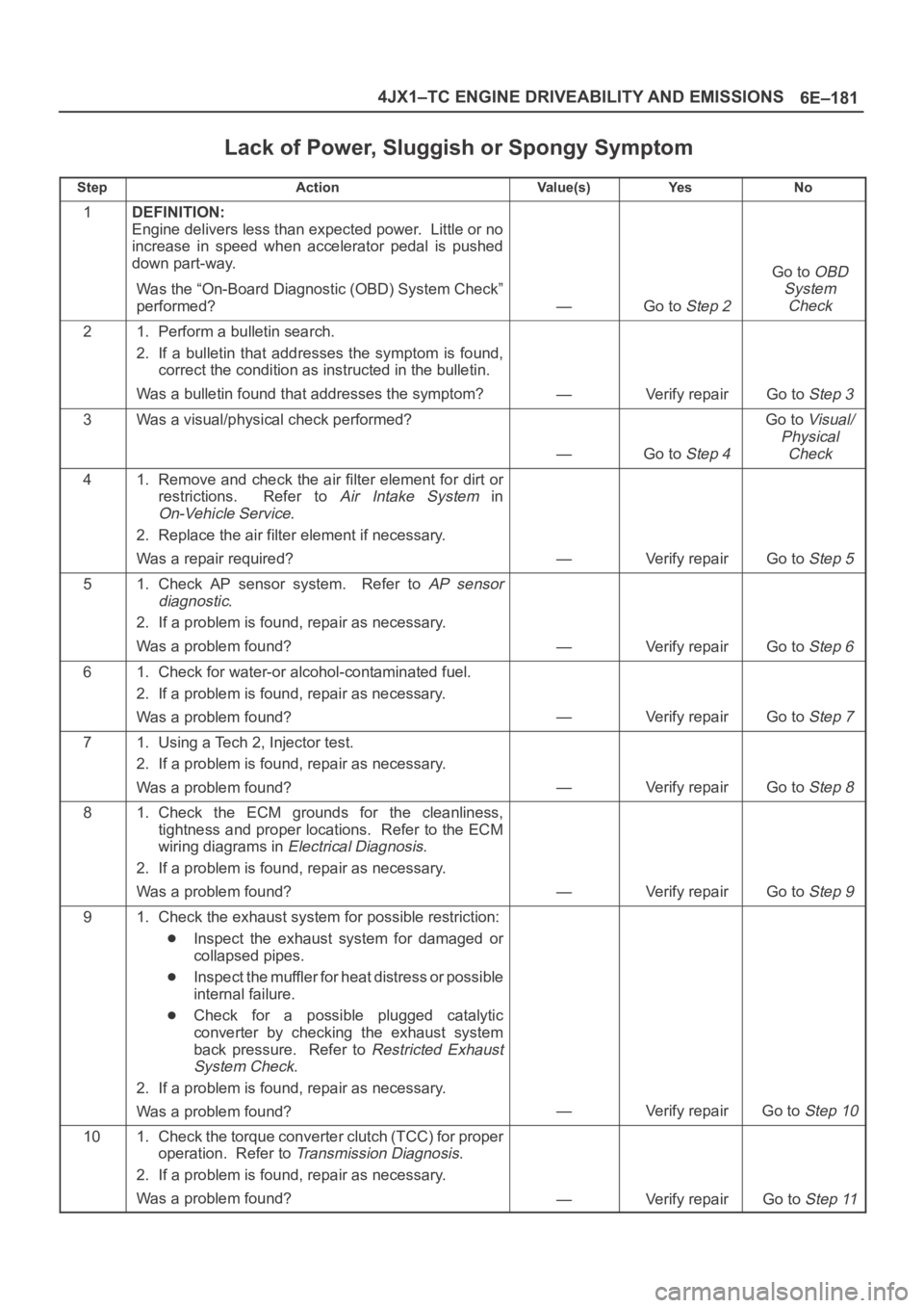
6E–181 4JX1–TC ENGINE DRIVEABILITY AND EMISSIONS
Lack of Power, Sluggish or Spongy Symptom
StepActionVa l u e ( s )Ye sNo
1DEFINITION:
Engine delivers less than expected power. Little or no
increase in speed when accelerator pedal is pushed
down part-way.
Was the “On-Board Diagnostic (OBD) System Check”
performed?
—Go to Step 2
Go to OBD
System
Check
21. Perform a bulletin search.
2. If a bulletin that addresses the symptom is found,
correct the condition as instructed in the bulletin.
Was a bulletin found that addresses the symptom?
—Verify repairGo to Step 3
3Was a visual/physical check performed?
—Go to Step 4
Go to Visual/
Physical
Check
41. Remove and check the air filter element for dirt or
restrictions. Refer to
Air Intake System in
On-Vehicle Service.
2. Replace the air filter element if necessary.
Was a repair required?
—Verify repairGo to Step 5
51. Check AP sensor system. Refer to AP sensor
diagnostic
.
2. If a problem is found, repair as necessary.
Was a problem found?
—Verify repairGo to Step 6
61. Check for water-or alcohol-contaminated fuel.
2. If a problem is found, repair as necessary.
Was a problem found?
—Verify repairGo to Step 7
71. Using a Tech 2, Injector test.
2. If a problem is found, repair as necessary.
Was a problem found?
—Verify repairGo to Step 8
81. Check the ECM grounds for the cleanliness,
tightness and proper locations. Refer to the ECM
wiring diagrams in
Electrical Diagnosis.
2. If a problem is found, repair as necessary.
Was a problem found?
—Verify repairGo to Step 9
91. Check the exhaust system for possible restriction:
Inspect the exhaust system for damaged or
collapsed pipes.
Inspect the muffler for heat distress or possible
internal failure.
Check for a possible plugged catalytic
converter by checking the exhaust system
back pressure. Refer to
Restricted Exhaust
System Check
.
2. If a problem is found, repair as necessary.
Was a problem found?
—Verify repairGo to Step 10
101. Check the torque converter clutch (TCC) for proper
operation. Refer to
Transmission Diagnosis.
2. If a problem is found, repair as necessary.
Was a problem found?
—Verify repairGo to Step 11
Page 5614 of 6000
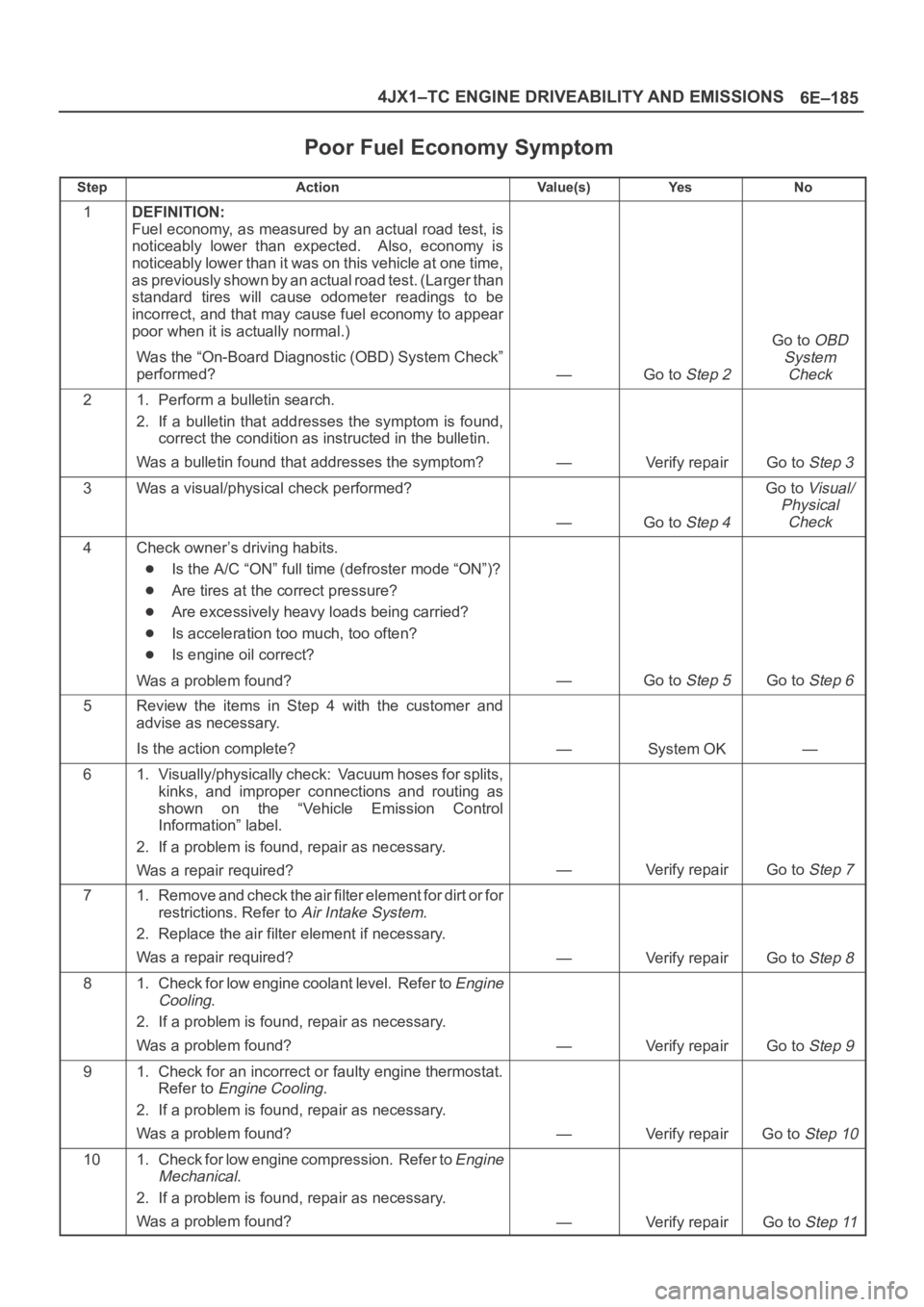
6E–185 4JX1–TC ENGINE DRIVEABILITY AND EMISSIONS
Poor Fuel Economy Symptom
StepActionVa l u e ( s )Ye sNo
1DEFINITION:
Fuel economy, as measured by an actual road test, is
noticeably lower than expected. Also, economy is
noticeably lower than it was on this vehicle at one time,
as previously shown by an actual road test. (Larger than
standard tires will cause odometer readings to be
incorrect, and that may cause fuel economy to appear
poor when it is actually normal.)
Was the “On-Board Diagnostic (OBD) System Check”
performed?
—Go to Step 2
Go to OBD
System
Check
21. Perform a bulletin search.
2. If a bulletin that addresses the symptom is found,
correct the condition as instructed in the bulletin.
Was a bulletin found that addresses the symptom?
—Verify repairGo to Step 3
3Was a visual/physical check performed?
—Go to Step 4
Go to Visual/
Physical
Check
4Check owner’s driving habits.
Is the A/C “ON” full time (defroster mode “ON”)?
Are tires at the correct pressure?
Are excessively heavy loads being carried?
Is acceleration too much, too often?
Is engine oil correct?
Was a problem found?
—Go to Step 5Go to Step 6
5Review the items in Step 4 with the customer and
advise as necessary.
Is the action complete?
—System OK—
61. Visually/physically check: Vacuum hoses for splits,
kinks, and improper connections and routing as
shown on the “Vehicle Emission Control
Information” label.
2. If a problem is found, repair as necessary.
Was a repair required?
—Verify repairGo to Step 7
71. Remove and check the air filter element for dirt or for
restrictions. Refer to
Air Intake System.
2. Replace the air filter element if necessary.
Was a repair required?
—Verify repairGo to Step 8
81. Check for low engine coolant level. Refer to Engine
Cooling
.
2. If a problem is found, repair as necessary.
Was a problem found?
—Verify repairGo to Step 9
91. Check for an incorrect or faulty engine thermostat.
Refer to
Engine Cooling.
2. If a problem is found, repair as necessary.
Was a problem found?
—Verify repairGo to Step 10
101. Check for low engine compression. Refer to Engine
Mechanical
.
2. If a problem is found, repair as necessary.
Was a problem found?
—Verify repairGo to Step 11
Page 5615 of 6000
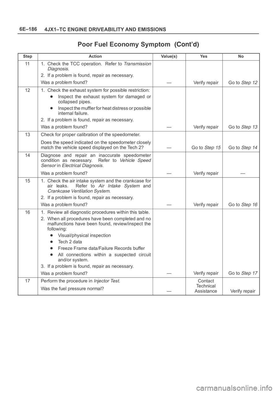
6E–186
4JX1–TC ENGINE DRIVEABILITY AND EMISSIONS
Poor Fuel Economy Symptom
StepNo Ye s Va l u e ( s ) Action
111. Check the TCC operation. Refer to Transmission
Diagnosis
.
2. If a problem is found, repair as necessary.
Was a problem found?
—Verify repairGo to Step 12
121. Check the exhaust system for possible restriction:
Inspect the exhaust system for damaged or
collapsed pipes.
Inspect the muffler for heat distress or possible
internal failure.
2. If a problem is found, repair as necessary.
Was a problem found?
—Verify repairGo to Step 13
13Check for proper calibration of the speedometer.
Does the speed indicated on the speedometer closely
match the vehicle speed displayed on the Tech 2?
—Go to Step 15Go to Step 14
14Diagnose and repair an inaccurate speedometer
condition as necessary. Refer to
Vehicle Speed
Sensor
in Electrical Diagnosis.
Was a problem found?
—Verify repair—
151. Check the air intake system and the crankcase for
air leaks. Refer to
Air Intake System and
Crankcase Ventilation System.
2. If a problem is found, repair as necessary.
Was a problem found?
—Verify repairGo to Step 16
161. Review all diagnostic procedures within this table.
2. When all procedures have been completed and no
malfunctions have been found, review/inspect the
following:
Visual/physical inspection
Te c h 2 d a t a
Freeze Frame data/Failure Records buffer
All connections within a suspected circuit
and/or system.
3. If a problem is found, repair as necessary.
Was a problem found?
—Verify repairGo to Step 17
17Perform the procedure in Injector Test.
Was the fuel pressure normal?
—
Contact
Te c h n i c a l
Assistance
Verify repair