Page 5005 of 6000

6E–348
ENGINE DRIVEABILITY AND EMISSIONS
oil to enter the cylinder, particularly if the deposits are
heavier on the side of the spark plug facing the intake
valve.
TS23995
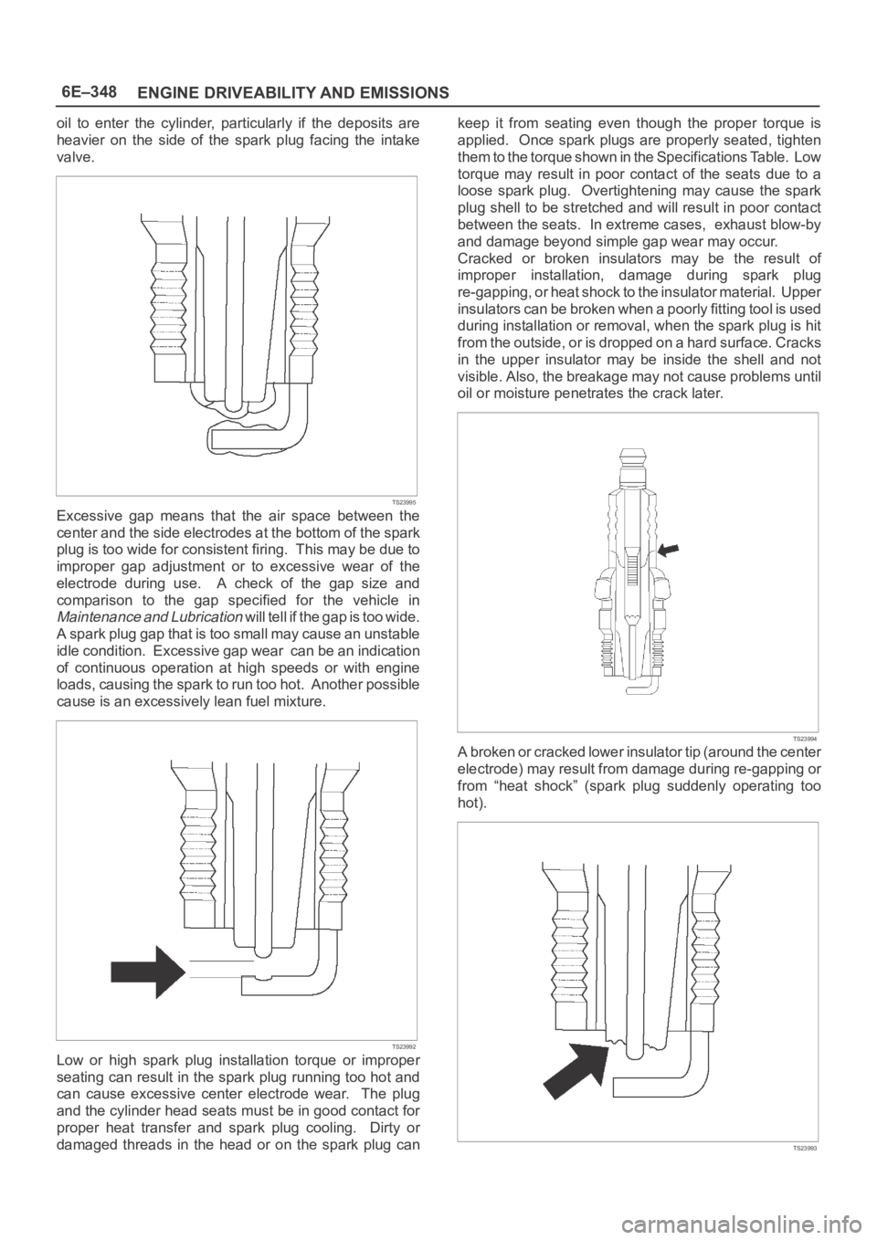
Excessive gap means that the air space between the
center and the side electrodes at the bottom of the spark
plug is too wide for consistent firing. This may be due to
improper gap adjustment or to excessive wear of the
electrode during use. A check of the gap size and
comparison to the gap specified for the vehicle in
Maintenance and Lubrication will tell if the gap is too wide.
A spark plug gap that is too small may cause an unstable
idle condition. Excessive gap wear can be an indication
of continuous operation at high speeds or with engine
loads, causing the spark to run too hot. Another possible
cause is an excessively lean fuel mixture.
TS23992
Low or high spark plug installation torque or improper
seating can result in the spark plug running too hot and
can cause excessive center electrode wear. The plug
and the cylinder head seats must be in good contact for
proper heat transfer and spark plug cooling. Dirty or
damaged threads in the head or on the spark plug cankeep it from seating even though the proper torque is
applied. Once spark plugs are properly seated, tighten
them to the torque shown in the Specifications Table. Low
torque may result in poor contact of the seats due to a
loose spark plug. Overtightening may cause the spark
plug shell to be stretched and will result in poor contact
between the seats. In extreme cases, exhaust blow-by
and damage beyond simple gap wear may occur.
Cracked or broken insulators may be the result of
improper installation, damage during spark plug
re-gapping, or heat shock to the insulator material. Upper
insulators can be broken when a poorly fitting tool is used
during installation or removal, when the spark plug is hit
from the outside, or is dropped on a hard surface. Cracks
in the upper insulator may be inside the shell and not
visible. Also, the breakage may not cause problems until
oil or moisture penetrates the crack later.
TS23994
A broken or cracked lower insulator tip (around the center
electrode) may result from damage during re-gapping or
from “heat shock” (spark plug suddenly operating too
hot).
TS23993
Page 5311 of 6000

6A – 38 ENGINE MECHANICAL
1. Cylinder head bolts for damaged threads or
stretching and damaged heads caused by improper
use of tools.
CAUTION: Suspected bolts must be replaced.
2. Cylinder head for cracks, especially between valve
seats and in the exhaust ports.
3. Cylinder head deck for corrosion, sand particles in
head and porosity.
CAUTION: Do not attempt to weld the cylinder
head. Replace it.
4. Cylinder head lower surface for flatness.
Use a straight edge and a feeler gauge to measure
the cylinder head lower surface warpage.
If the measured values exceed the specified limit,
the cylinder head must be replaced.
Cylinder Head Lower Face Warpage:
Standard: 0.075 mm (0.0029 in) or less
Limit: 0.50 mm (0.0197 in)
Cylinder Head Height:
Standard: 95 mm (3.740 in)
5. Water jacket sealing plugs seating surfaces.
6. Use a straight edge and a feeler gauge to measure
the manifold cylinder head fitting face warpage.
If the measured values exceed the specified limit,
the manifold must be replaced.
Exhaust Manifold Warpage:
Standard: 0.05 mm (0.0020 in) or less
Limit: 0.20 mm (0.0079 in)
CAUTION: Do not attempt to weld the cylinder
head. Replace it.
REASSEMBLY
1. Cylinder Head
Refer to “Cylinder head”.
2. Glow Plug and Glow Plug Connector
Tighten glow plugs.
Torque: 15 Nꞏm (1.5 kgꞏm/11 lb ft)
011RW006
012RW053
Page 5345 of 6000

6A – 72 ENGINE MECHANICAL
7) Apply plastigage to the crankshaft journal unit as
shown in the illustration.
8) Install the main bearing caps. Apply engine oil to
the bolt threads and the seats. Tighten the bolts
to the specified torque.
Torque: 167 Nꞏm (17 kgꞏm/123 lb ft)
NOTE: Do not allow the crankshaft to rotate.
9) Remove the main bearing caps.
10) Measure the plastigage width and determine the
oil clearance. If the oil clearance exceeds the
specified limit, replace the main bearings as a
set and/or replace the crankshaft.
11) Clean the plastigage from the bearings and the
crankshaft.
Remove the crankshaft and the bearings.
Standard: 0.031 – 0.063 mm (0.0012 – 0.0025 in)
Limit: 0.11 mm (0.0043 in)3. Run-out
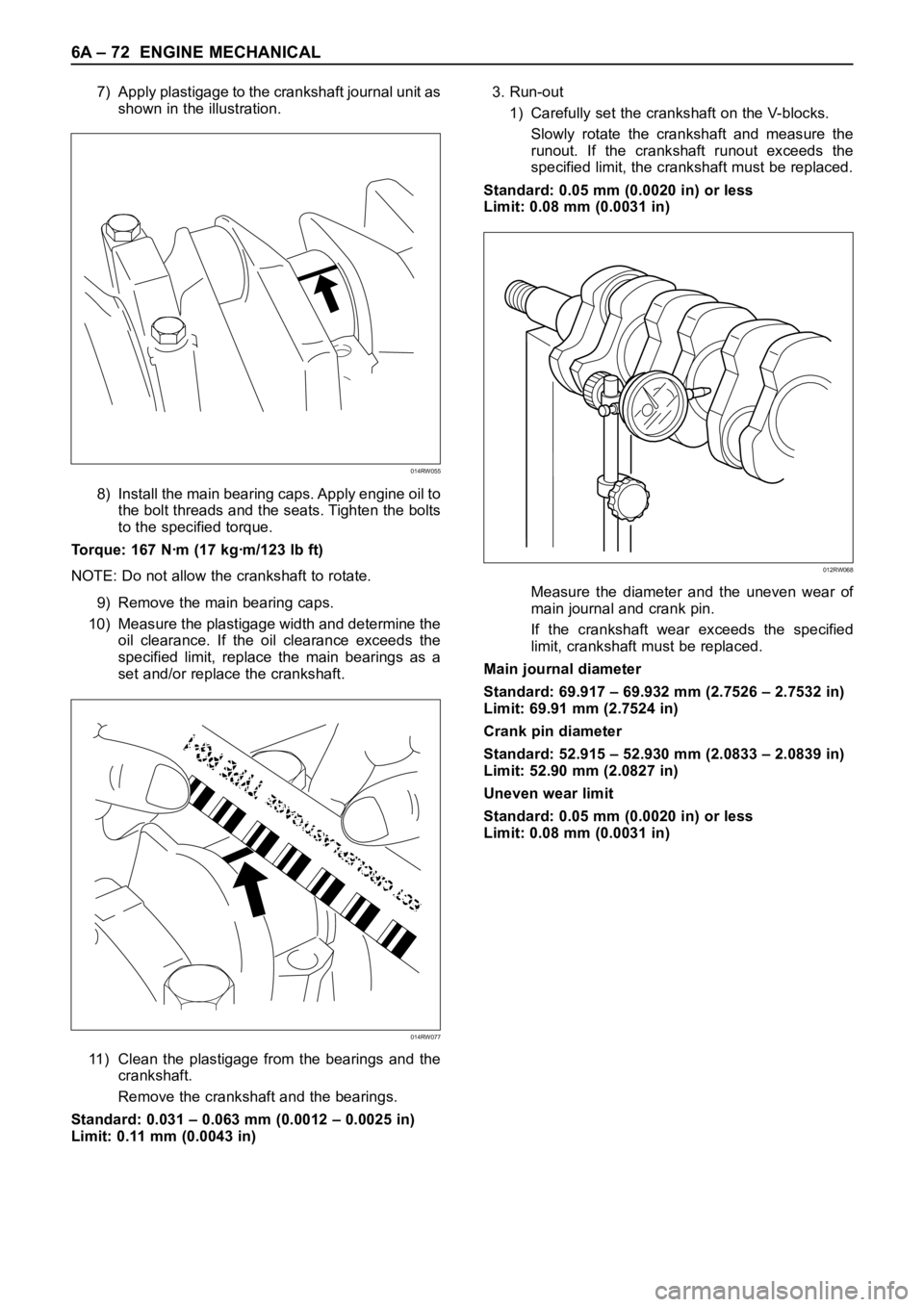
1) Carefully set the crankshaft on the V-blocks.
Slowly rotate the crankshaft and measure the
runout. If the crankshaft runout exceeds the
specified limit, the crankshaft must be replaced.
Standard: 0.05 mm (0.0020 in) or less
Limit: 0.08 mm (0.0031 in)
Measure the diameter and the uneven wear of
main journal and crank pin.
If the crankshaft wear exceeds the specified
limit, crankshaft must be replaced.
Main journal diameter
Standard: 69.917 – 69.932 mm (2.7526 – 2.7532 in)
Limit: 69.91 mm (2.7524 in)
Crank pin diameter
Standard: 52.915 – 52.930 mm (2.0833 – 2.0839 in)
Limit: 52.90 mm (2.0827 in)
Uneven wear limit
Standard: 0.05 mm (0.0020 in) or less
Limit: 0.08 mm (0.0031 in)
014RW055
014RW077
012RW068