1998 OPEL FRONTERA transmission fluid
[x] Cancel search: transmission fluidPage 2198 of 6000
7A–44
AUTOMATIC TRANSMISSION (4L30–E)
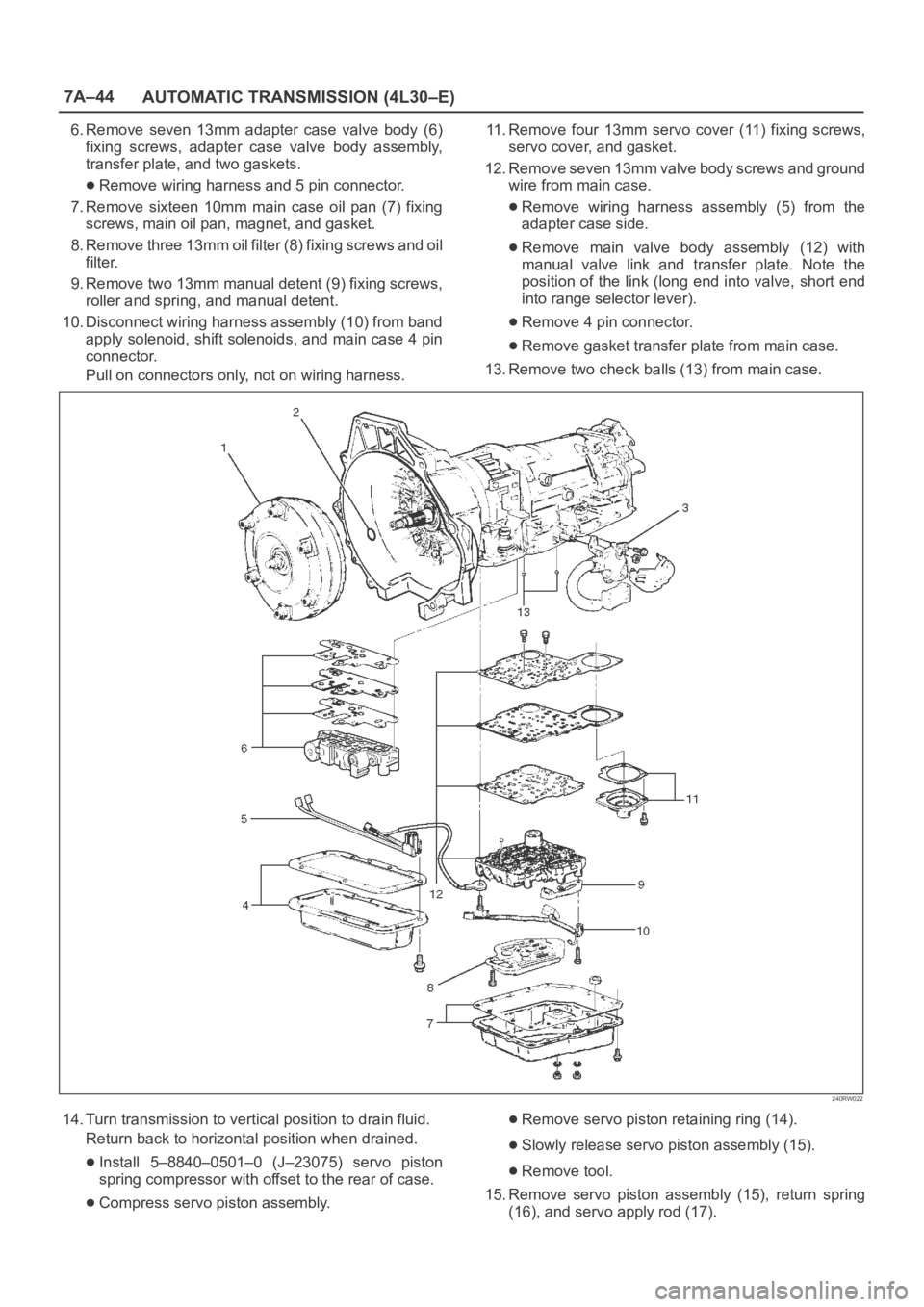
6. Remove seven 13mm adapter case valve body (6)
fixing screws, adapter case valve body assembly,
transfer plate, and two gaskets.
Remove wiring harness and 5 pin connector.
7. Remove sixteen 10mm main case oil pan (7) fixing
screws, main oil pan, magnet, and gasket.
8. Remove three 13mm oil filter (8) fixing screws and oil
filter.
9. Remove two 13mm manual detent (9) fixing screws,
roller and spring, and manual detent.
10. Disconnect wiring harness assembly (10) from band
apply solenoid, shift solenoids, and main case 4 pin
connector.
Pull on connectors only, not on wiring harness.11. Remove four 13mm servo cover (11) fixing screws,
servo cover, and gasket.
12. Remove seven 13mm valve body screws and ground
wire from main case.
Remove wiring harness assembly (5) from the
adapter case side.
Remove main valve body assembly (12) with
manual valve link and transfer plate. Note the
position of the link (long end into valve, short end
into range selector lever).
Remove 4 pin connector.
Remove gasket transfer plate from main case.
13. Remove two check balls (13) from main case.
240RW022
14. Turn transmission to vertical position to drain fluid.
Return back to horizontal position when drained.
Install 5–8840–0501–0 (J–23075) servo piston
spring compressor with offset to the rear of case.
Compress servo piston assembly.
Remove servo piston retaining ring (14).
Slowly release servo piston assembly (15).
Remove tool.
15. Remove servo piston assembly (15), return spring
(16), and servo apply rod (17).
Page 2209 of 6000
7A–55 AUTOMATIC TRANSMISSION (4L30–E)
242RW008
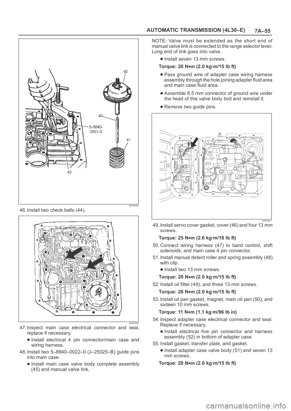
46. Install two check balls (44).
244RW002
47. Inspect main case electrical connector and seal,
replace if necessary.
Install electrical 4 pin connector/main case and
wiring harness.
48. Install two 5–8840–0022–0 (J–25025–B) guide pins
into main case.
Install main case valve body complete assembly
(45) and manual valve link.NOTE: Valve must be extended as the short end of
manual valve link is connected to the range selector lever.
Long end of link goes into valve.
Install seven 13 mm screws.
To r q u e : 2 0 N
m (2.0 kgꞏm/15 lb ft)
Pass ground wire of adapter case wiring harness
assembly through the hole joining adapter fluid area
and main case fluid area.
Assemble 8.5 mm connector of ground wire under
the head of this valve body bolt and reinstall it.
Remove two guide pins.
244RW001
49. Install servo cover gasket, cover (46) and four 13 mm
screws.
To r q u e : 2 5 N
m (2.6 kgꞏm/18 lb ft)
50. Connect wiring harness (47) to band control, shift
solenoids, and main case 4 pin connector.
51. Install manual detent roller and spring assembly (48)
with clip.
Install two 13 mm screws.
To r q u e : 2 0 N
m (2.0 kgꞏm/15 lb ft)
52. Install oil filter (49), and three 13 mm screws.
To r q u e : 2 0 N
m (2.0 kgꞏm/15 lb ft)
53. Install oil pan gasket, magnet, main oil pan (50), and
sixteen 10 mm screws.
To r q u e : 11 N
m (1.1 kgꞏm/96 lb in)
54. Inspect adapter case electrical connector and seal.
Replace if necessary.
Install electrical five pin connector and harness
assembly (52) in bottom of adapter case.
55. Install gasket, transfer plate, and gasket.
Install adapter case valve body (51) and seven 13
mm screws.
Torque: 20 N
m (2.0 kgꞏm/15 lb ft)
Page 2210 of 6000
7A–56
AUTOMATIC TRANSMISSION (4L30–E)
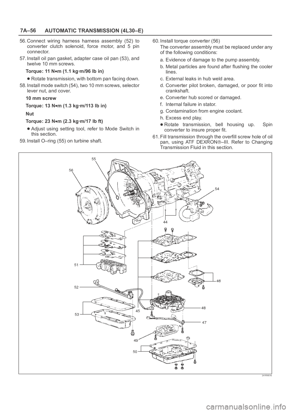
56. Connect wiring harness harness assembly (52) to
converter clutch solenoid, force motor, and 5 pin
connector.
57. Install oil pan gasket, adapter case oil pan (53), and
twelve 10 mm screws.
Torque: 11 N
m (1.1 kgꞏm/96 lb in)
Rotate transmission, with bottom pan facing down.
58. Install mode switch (54), two 10 mm screws, selector
lever nut, and cover.
10 mm screw
Torque: 13 N
m (1.3 kgꞏm/113 lb in)
Nut
Torque: 23 N
m (2.3 kgꞏm/17 lb ft)
Adjust using setting tool, refer to Mode Switch in
this section.
59. Install O–ring (55) on turbine shaft.60. Install torque converter (56)
The converter assembly must be replaced under any
of the following conditions:
a. Evidence of damage to the pump assembly.
b. Metal particles are found after flushing the cooler
lines.
c. External leaks in hub weld area.
d. Converter pilot broken, damaged, or poor fit into
crankshaft.
e. Converter hub scored or damaged.
f. Internal failure in stator.
g. Contamination from engine coolant.
h. Excess end play.Rotate transmission, bell housing up. Spin
converter to insure proper fit.
61. Fill transmission through the overfill screw hole of oil
pan, using ATF DEXRON
–III. Refer to Changing
Transmission Fluid in this section.
241RW016
Page 2219 of 6000
7A–65 AUTOMATIC TRANSMISSION (4L30–E)
Third Clutch
Disassembled View
248RS006
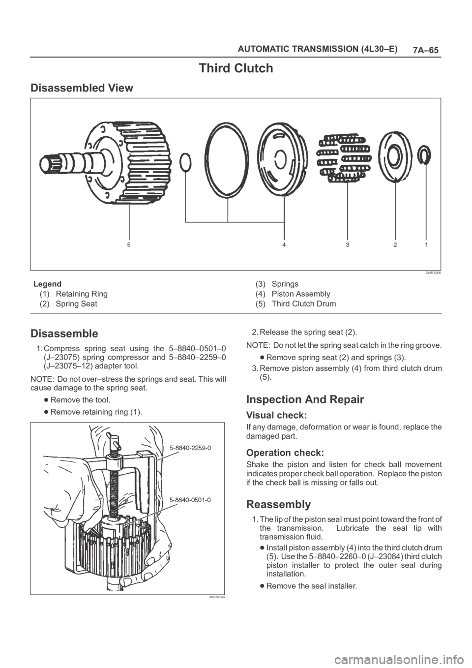
Legend
(1) Retaining Ring
(2) Spring Seat(3) Springs
(4) Piston Assembly
(5) Third Clutch Drum
Disassemble
1. Compress spring seat using the 5–8840–0501–0
(J–23075) spring compressor and 5–8840–2259–0
(J–23075–12) adapter tool.
NOTE: Do not over–stress the springs and seat. This will
cause damage to the spring seat.
Remove the tool.
Remove retaining ring (1).
248RW004
2. Release the spring seat (2).
NOTE: Do not let the spring seat catch in the ring groove.
Remove spring seat (2) and springs (3).
3. Remove piston assembly (4) from third clutch drum
(5).
Inspection And Repair
Visual check:
If any damage, deformation or wear is found, replace the
damaged part.
Operation check:
Shake the piston and listen for check ball movement
indicates proper check ball operation. Replace the piston
if the check ball is missing or falls out.
Reassembly
1. The lip of the piston seal must point toward the front of
the transmission. Lubricate the seal lip with
transmission fluid.
Install piston assembly (4) into the third clutch drum
(5). Use the 5–8840–2260–0 (J–23084) third clutch
piston installer to protect the outer seal during
installation.
Remove the seal installer.
Page 2223 of 6000
7A–69 AUTOMATIC TRANSMISSION (4L30–E)
Inspection And Repair
Visual Check:
If any damage, deformation or wear is found, replace the
damaged part.
Operation Check:
Shake the piston and listen for check ball movement.
Movement indicates proper check ball operation.
Replace the piston if the check ball is missing or falls out.
Reassembly
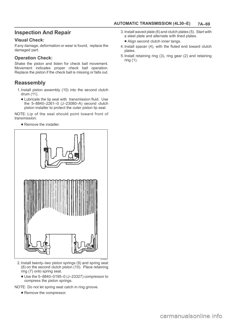
1. Install piston assembly (10) into the second clutch
drum (11).
Lubricate the lip seal with transmission fluid. Use
the 5–8840–2261–0 (J–23080–A) second clutch
piston installer to protect the outer piston lip seal.
NOTE: Lip of the seal should point toward front of
transmission.
Remove the installer.
247RS007
2. Install twenty–two piston springs (9) and spring seat
(8) on the second clutch piston (10). Place retaining
ring (7) onto spring seat.
Use the 5–8840–0195–0 (J–23327) compressor to
compress the piston springs.
NOTE: Do not let spring seat catch in ring groove.
Remove the compressor.3. Install waved plate (6) and clutch plates (5). Start with
a steel plate and alternate with lined plates.
Align second clutch inner tangs.
4. Install spacer (4), with the fluted end toward clutch
plates.
5. Install retaining ring (3), ring gear (2) and retaining
ring (1).
Page 2246 of 6000
TRANSMISSION CONTROL SYSTEM (4L30–E)7A1–1
TRANSMISSION
TRANSMISSION CONTROL SYSTEM (4L30–E)
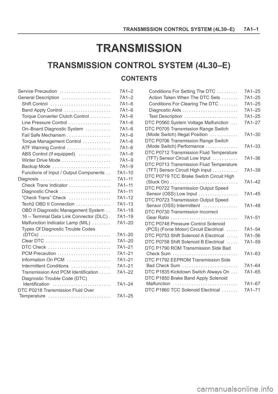
CONTENTS
Service Precaution 7A1–2. . . . . . . . . . . . . . . . . . . . . .
General Description 7A1–2. . . . . . . . . . . . . . . . . . . . .
Shift Control 7A1–6. . . . . . . . . . . . . . . . . . . . . . . . . .
Band Apply Control 7A1–6. . . . . . . . . . . . . . . . . . . .
Torque Converter Clutch Control 7A1–6. . . . . . . . .
Line Pressure Control 7A1–6. . . . . . . . . . . . . . . . . .
On–Board Diagnostic System 7A1–6. . . . . . . . . . .
Fail Safe Mechanism 7A1–6. . . . . . . . . . . . . . . . . . .
Torque Management Control 7A1–6. . . . . . . . . . . .
ATF Warning Control 7A1–6. . . . . . . . . . . . . . . . . . .
ABS Control (If equipped) 7A1–6. . . . . . . . . . . . . .
Winter Drive Mode 7A1–9. . . . . . . . . . . . . . . . . . . . .
Backup Mode 7A1–9. . . . . . . . . . . . . . . . . . . . . . . . .
Functions of Input / Output Components 7A1–10. .
Diagnosis 7A1–11. . . . . . . . . . . . . . . . . . . . . . . . . . . . . .
Check Trans Indicator 7A1–11. . . . . . . . . . . . . . . . . .
Diagnostic Check 7A1–11. . . . . . . . . . . . . . . . . . . . . .
“Check Trans” Check 7A1–12. . . . . . . . . . . . . . . . . .
Tech2 OBD II Connection 7A1–13. . . . . . . . . . . . . . .
OBD II Diagnostic Management System 7A1–18. .
16 – Terminal Data Link Connector (DLC) 7A1–19.
Malfunction Indicator Lamp (MIL) 7A1–20. . . . . . . .
Types Of Diagnostic Trouble Codes
(DTCs) 7A1–20. . . . . . . . . . . . . . . . . . . . . . . . . . . . . .
Clear DTC 7A1–20. . . . . . . . . . . . . . . . . . . . . . . . . . . .
DTC Check 7A1–21. . . . . . . . . . . . . . . . . . . . . . . . . . .
PCM Precaution 7A1–21. . . . . . . . . . . . . . . . . . . . . . .
Information On PCM 7A1–21. . . . . . . . . . . . . . . . . . .
Intermittent Conditions 7A1–21. . . . . . . . . . . . . . . . .
Transmission And PCM Identification 7A1–22. . . . .
Diagnostic Trouble Code (DTC)
Identification 7A1–24. . . . . . . . . . . . . . . . . . . . . . . . .
DTC P0218 Transmission Fluid Over
Temperature 7A1–25. . . . . . . . . . . . . . . . . . . . . . . . . . . Conditions For Setting The DTC 7A1–25. . . . . . . . .
Action Taken When The DTC Sets 7A1–25. . . . . . .
Conditions For Clearing The DTC 7A1–25. . . . . . . .
Diagnostic Aids 7A1–25. . . . . . . . . . . . . . . . . . . . . . . .
Test Description 7A1–25. . . . . . . . . . . . . . . . . . . . . . .
DTC P0560 System Voltage Malfunction 7A1–27. . .
DTC P0705 Transmission Range Switch
(Mode Switch) Illegal Position 7A1–30. . . . . . . . . . . .
DTC P0706 Transmission Range Switch
(Mode Switch) Performance 7A1–33. . . . . . . . . . . . . .
DTC P0712 Transmission Fluid Temperature
(TFT) Sensor Circuit Low Input 7A1–36. . . . . . . . . . .
DTC P0713 Transmission Fluid Temperature
(TFT) Sensor Circuit High Input 7A1–39. . . . . . . . . . .
DTC P0719 TCC Brake Switch Circuit High
(Stuck On) 7A1–42. . . . . . . . . . . . . . . . . . . . . . . . . . . . .
DTC P0722 Transmission Output Speed
Sensor (OSS) Low Input 7A1–45. . . . . . . . . . . . . . . . .
DTC P0723 Transmission Output Speed
Sensor (OSS) Intermittent 7A1–48. . . . . . . . . . . . . . .
DTC P0730 Transmission Incorrect
Gear Ratio 7A1–51. . . . . . . . . . . . . . . . . . . . . . . . . . . . .
DTC P0748 Pressure Control Solenoid
(PCS) (Force Motor) Circuit Electrical 7A1–54. . . . .
DTC P0753 Shift Solenoid A Electrical 7A1–56. . . . .
DTC P0758 Shift Solenoid B Electrical 7A1–59. . . . .
DTC P1790 ROM Transmission Side Bad
Check Sum 7A1–63. . . . . . . . . . . . . . . . . . . . . . . . . . . .
DTC P1792 EEPROM Transmission Side
Bad Check Sum 7A1–64. . . . . . . . . . . . . . . . . . . . . . . .
DTC P1835 Kickdown Switch Always On 7A1–65. . .
DTC P1850 Brake Band Apply Solenoid
Malfunction 7A1–67. . . . . . . . . . . . . . . . . . . . . . . . . . . .
DTC P1860 TCC Solenoid Electrical 7A1–71. . . . . . .
Page 2269 of 6000
7A1–24
TRANSMISSION CONTROL SYSTEM (4L30–E)
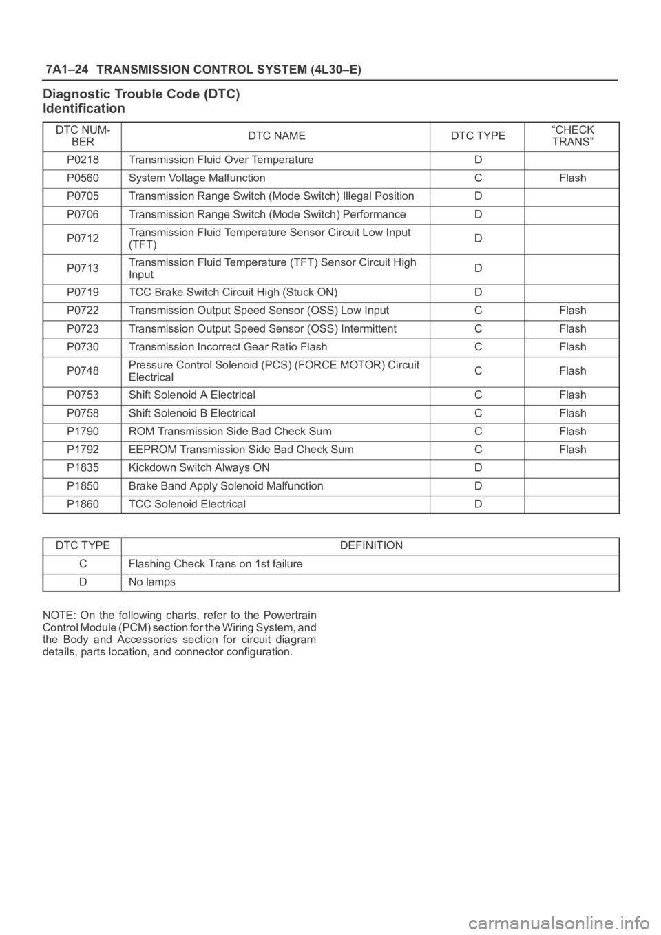
Diagnostic Trouble Code (DTC)
Identification
DTC NUM-
BERDTC NAMEDTC TYPE“CHECK
TRANS”
P0218Transmission Fluid Over TemperatureD
P0560System Voltage MalfunctionCFlash
P0705Transmission Range Switch (Mode Switch) Illegal PositionD
P0706Transmission Range Switch (Mode Switch) PerformanceD
P0712Transmission Fluid Temperature Sensor Circuit Low Input
(TFT)D
P0713Transmission Fluid Temperature (TFT) Sensor Circuit High
InputD
P0719TCC Brake Switch Circuit High (Stuck ON)D
P0722Transmission Output Speed Sensor (OSS) Low InputCFlash
P0723Transmission Output Speed Sensor (OSS) IntermittentCFlash
P0730Transmission Incorrect Gear Ratio FlashCFlash
P0748Pressure Control Solenoid (PCS) (FORCE MOTOR) Circuit
ElectricalCFlash
P0753Shift Solenoid A ElectricalCFlash
P0758Shift Solenoid B ElectricalCFlash
P1790ROM Transmission Side Bad Check SumCFlash
P1792EEPROM Transmission Side Bad Check SumCFlash
P1835Kickdown Switch Always OND
P1850Brake Band Apply Solenoid MalfunctionD
P1860TCC Solenoid ElectricalD
DTC TYPEDEFINITION
CFlashing Check Trans on 1st failure
DNo lamps
NOTE: On the following charts, refer to the Powertrain
Control Module (PCM) section for the Wiring System, and
the Body and Accessories section for circuit diagram
details, parts location, and connector configuration.
Page 2270 of 6000
TRANSMISSION CONTROL SYSTEM (4L30–E)7A1–25
DTC P0218 Transmission Fluid Over Temperature
D07RW029
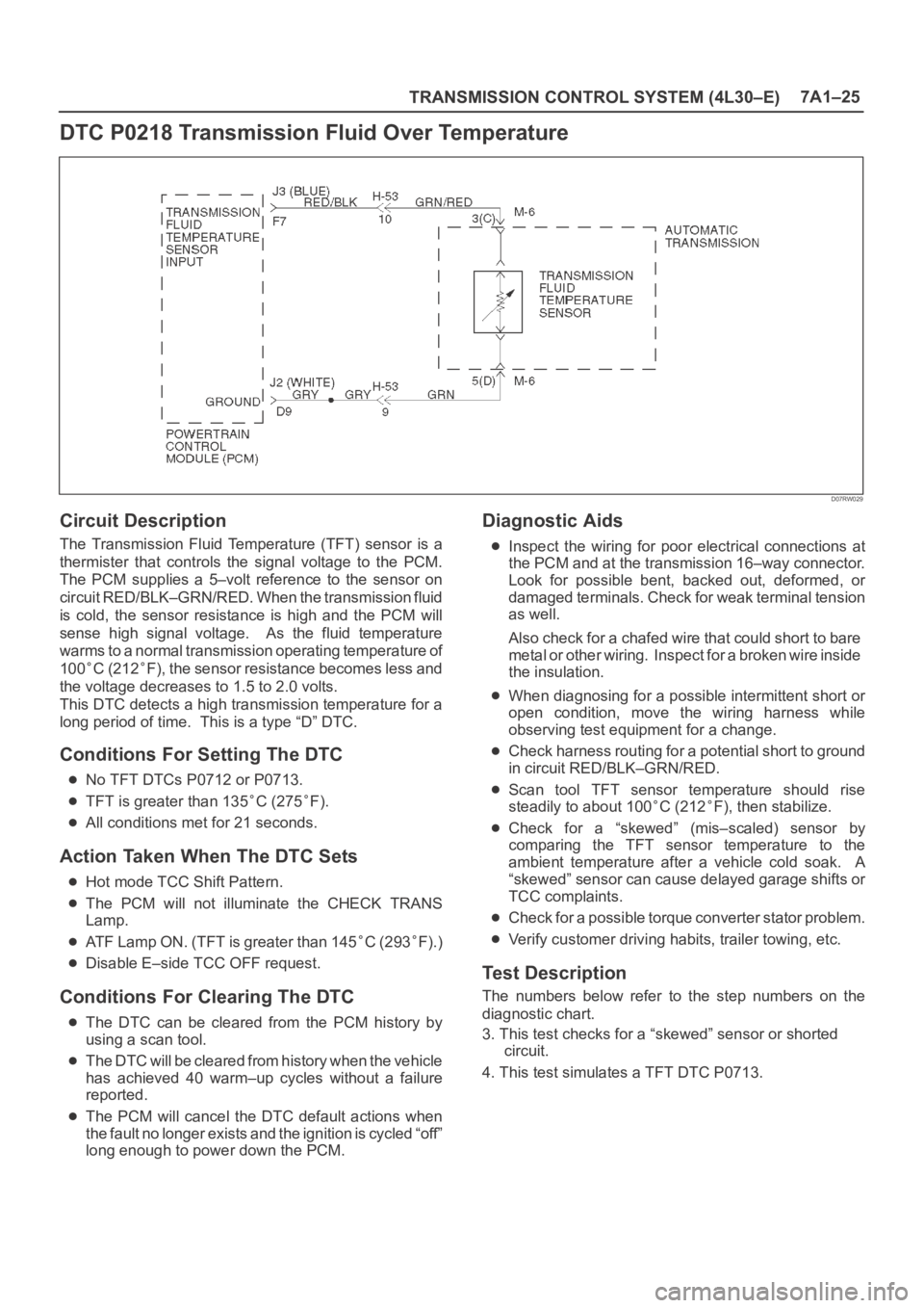
Circuit Description
The Transmission Fluid Temperature (TFT) sensor is a
thermister that controls the signal voltage to the PCM.
The PCM supplies a 5–volt reference to the sensor on
circuit RED/BLK–GRN/RED. When the transmission fluid
is cold, the sensor resistance is high and the PCM will
sense high signal voltage. As the fluid temperature
warms to a normal transmission operating temperature of
100
C (212F), the sensor resistance becomes less and
the voltage decreases to 1.5 to 2.0 volts.
This DTC detects a high transmission temperature for a
long period of time. This is a type “D” DTC.
Conditions For Setting The DTC
No TFT DTCs P0712 or P0713.
TFT is greater than 135C (275F).
All conditions met for 21 seconds.
Action Taken When The DTC Sets
Hot mode TCC Shift Pattern.
The PCM will not illuminate the CHECK TRANS
Lamp.
ATF Lamp ON. (TFT is greater than 145C (293F).)
Disable E–side TCC OFF request.
Conditions For Clearing The DTC
The DTC can be cleared from the PCM history by
using a scan tool.
The DTC will be cleared from history when the vehicle
has achieved 40 warm–up cycles without a failure
reported.
The PCM will cancel the DTC default actions when
the fault no longer exists and the ignition is cycled “off”
long enough to power down the PCM.
Diagnostic Aids
Inspect the wiring for poor electrical connections at
the PCM and at the transmission 16–way connector.
Look for possible bent, backed out, deformed, or
damaged terminals. Check for weak terminal tension
as well.
Also check for a chafed wire that could short to bare
metal or other wiring. Inspect for a broken wire inside
the insulation.
When diagnosing for a possible intermittent short or
open condition, move the wiring harness while
observing test equipment for a change.
Check harness routing for a potential short to ground
in circuit RED/BLK–GRN/RED.
Scan tool TFT sensor temperature should rise
steadily to about 100
C (212F), then stabilize.
Check for a “skewed” (mis–scaled) sensor by
comparing the TFT sensor temperature to the
ambient temperature after a vehicle cold soak. A
“skewed” sensor can cause delayed garage shifts or
TCC complaints.
Check for a possible torque converter stator problem.
Verify customer driving habits, trailer towing, etc.
Test Description
The numbers below refer to the step numbers on the
diagnostic chart.
3. This test checks for a “skewed” sensor or shorted
circuit.
4. This test simulates a TFT DTC P0713.