1998 OPEL FRONTERA transmission fluid
[x] Cancel search: transmission fluidPage 1182 of 6000
6E–65 ENGINE DRIVEABILITY AND EMISSIONS
Knock Sensor Diagnosis
The Tech 2 has two data displays available for diagnosing
the knock sensor (KS) system. The two displays are
described as follows:
“Knock Retard” indicates the number of degrees that
the spark timing is being retarded due to a knock
condition.
“KS Noise Channel” indicates the current voltage level
being monitored on the noise channel.
DTCs P0325 and P0327 are designed to diagnose the KS
module, the knock sensor, and the related wiring. The
problems encountered with the KS system should set a
DTC. However, if no DTC was set but the KS system is
suspect because of a detonation complaint, refer to
Detonation/Spark Knock in Symptoms.
Powertrain Control Module (PCM)
Diagnosis
To read and clear diagnostic trouble codes, use a Tech 2.
IMPORTANT:Use of a Tech 2 is recommended to clear
diagnostic trouble codes from the PCM memory.
Diagnostic trouble codes can also be cleared by turning
the ignition “OFF” and disconnecting the battery power
from the PCM for 30 seconds. Turning off the ignition and
disconnecting the battery power from the PCM will cause
all diagnostic information in the PCM memory to be
cleared. Therefore, all the diagnostic tests will have to be
re-run.
Since the PCM can have a failure which may affect only
one circuit, following the diagnostic procedures in this
section will determine which circuit has a problem and
where it is.
If a diagnostic chart indicates that the PCM connections
or the PCM is the cause of a problem, and the PCM is
replaced, but this does not correct the problem, one of the
following may be the reason:
There is a problem with the PCM terminal connections.
The terminals may have to be removed from the
connector in order to check them properly.
The problem is intermittent. This means that the
problem is not present at the time the system is being
checked. In this case, refer to the
Symptoms p o r t i o n o f
the manual and make a careful physical inspection of
all component and wiring associated with the affected
system.
There is a shorted solenoid, relay coil, or harness.
S o l e n o i d s a n d r e l a y s a r e t u r n e d “ O N ” a n d “ O F F ” b y t h e
PCM using internal electronic switches called drivers.
A shorted solenoid, relay coil, or harness will not
damage the PCM but will cause the solenoid or relay to
be inoperative.
Multiple PCM Information Sensor
DTCS Set
Circuit Description
The powertrain control module (PCM) monitors various
sensors to determine the engine operating conditions.
The PCM controls fuel delivery, spark advance,
transmission operation, and emission control device
operation based on the sensor inputs.The PCM provides a sensor ground to all of the sensors.
The PCM applies 5 volts through a pull-up resistor, and
determines the status of the following sensors by
monitoring the voltage present between the 5-volt supply
and the resistor:
The engine coolant temperature (ETC) sensor
The intake air temperature (IAT) sensor
The transmission fluid temperature (TFT) sensor
The PCM provides the following sensors with a 5-volt
reference and a sensor ground signal:
The exhaust gas recirculating (EGR) pintle position
sensor
The throttle position (TP) sensor
The manifold absolute pressure (MAP) sensor
The PCM monitors the separate feedback signals from
these sensors in order to determine their operating
status.
Diagnostic Aids
IMPORTANT:Be sure to inspect PCM and engine
grounds for being secure and clean.
A short to voltage in one of the sensor input circuits may
cause one or more of the following DTCs to be set:
P0108
P0113
P0118
P0123
P0560
P0712
P0406
IMPORTANT:If a sensor input circuit has been shorted
to voltage, ensure that the sensor is not damaged. A
damaged sensor will continue to indicate a high or low
voltage after the affected circuit has been repaired. If the
sensor has been damaged, replace it.
An open in the sensor ground circuit between the PCM
and the splice will cause one or more of the following
DTCs to be set:
P0108
P0113
P0118
P0123
P0712
P0406
A short to ground in the 5-volt reference A or B circuit will
cause one or more of the following DTCs to be set:
P0107
P0122
In the 5-volt reference circuit A, between the PCM and the
splice, will cause one or more of the following DTCs to be
set:
P0122
In the 5-volt reference circuit B, between the PCM and the
splice, will cause one or more of the following DTCs to be
set:
P0107
Check for the following conditions:
Page 1229 of 6000
6E–112
ENGINE DRIVEABILITY AND EMISSIONS
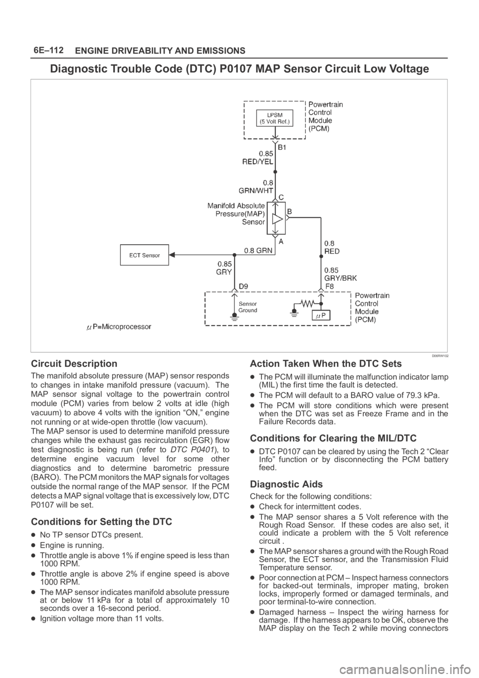
Diagnostic Trouble Code (DTC) P0107 MAP Sensor Circuit Low Voltage
D06RW102
Circuit Description
The manifold absolute pressure (MAP) sensor responds
to changes in intake manifold pressure (vacuum). The
MAP sensor signal voltage to the powertrain control
module (PCM) varies from below 2 volts at idle (high
vacuum) to above 4 volts with the ignition “ON,” engine
not running or at wide-open throttle (low vacuum).
The MAP sensor is used to determine manifold pressure
changes while the exhaust gas recirculation (EGR) flow
test diagnostic is being run (refer to
DTC P0401), to
determine engine vacuum level for some other
diagnostics and to determine barometric pressure
(BARO). The PCM monitors the MAP signals for voltages
outside the normal range of the MAP sensor. If the PCM
detects a MAP signal voltage that is excessively low, DTC
P0107 will be set.
Conditions for Setting the DTC
No TP sensor DTCs present.
Engine is running.
Throttle angle is above 1% if engine speed is less than
1000 RPM.
Throttle angle is above 2% if engine speed is above
1000 RPM.
The MAP sensor indicates manifold absolute pressure
at or below 11 kPa for a total of approximately 10
seconds over a 16-second period.
Ignition voltage more than 11 volts.
Action Taken When the DTC Sets
The PCM will illuminate the malfunction indicator lamp
(MIL) the first time the fault is detected.
The PCM will default to a BARO value of 79.3 kPa.
The PCM will store conditions which were present
when the DTC was set as Freeze Frame and in the
Failure Records data.
Conditions for Clearing the MIL/DTC
DTC P0107 can be cleared by using the Tech 2 “Clear
Info” function or by disconnecting the PCM battery
feed.
Diagnostic Aids
Check for the following conditions:
Check for intermittent codes.
The MAP sensor shares a 5 Volt reference with the
Rough Road Sensor. If these codes are also set, it
could indicate a problem with the 5 Volt reference
circuit .
The MAP sensor shares a ground with the Rough Road
Sensor, the ECT sensor, and the Transmission Fluid
Temperature sensor.
Poor connection at PCM – Inspect harness connectors
for backed-out terminals, improper mating, broken
locks, improperly formed or damaged terminals, and
poor terminal-to-wire connection.
Damaged harness – Inspect the wiring harness for
damage. If the harness appears to be OK, observe the
MAP display on the Tech 2 while moving connectors
Page 1244 of 6000
6E–127 ENGINE DRIVEABILITY AND EMISSIONS
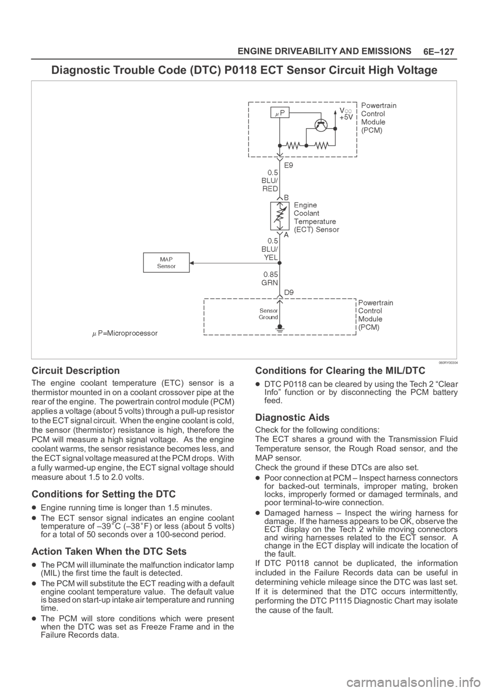
Diagnostic Trouble Code (DTC) P0118 ECT Sensor Circuit High Voltage
060RY00304
Circuit Description
The engine coolant temperature (ETC) sensor is a
thermistor mounted in on a coolant crossover pipe at the
rear of the engine. The powertrain control module (PCM)
applies a voltage (about 5 volts) through a pull-up resistor
to the ECT signal circuit. When the engine coolant is cold,
the sensor (thermistor) resistance is high, therefore the
PCM will measure a high signal voltage. As the engine
coolant warms, the sensor resistance becomes less, and
the ECT signal voltage measured at the PCM drops. With
a fully warmed-up engine, the ECT signal voltage should
measure about 1.5 to 2.0 volts.
Conditions for Setting the DTC
Engine running time is longer than 1.5 minutes.
The ECT sensor signal indicates an engine coolant
temperature of –39C (–38F) or less (about 5 volts)
for a total of 50 seconds over a 100-second period.
Action Taken When the DTC Sets
The PCM will illuminate the malfunction indicator lamp
(MIL) the first time the fault is detected.
The PCM will substitute the ECT reading with a default
engine coolant temperature value. The default value
is based on start-up intake air temperature and running
time.
The PCM will store conditions which were present
when the DTC was set as Freeze Frame and in the
Failure Records data.
Conditions for Clearing the MIL/DTC
DTC P0118 can be cleared by using the Tech 2 “Clear
Info” function or by disconnecting the PCM battery
feed.
Diagnostic Aids
Check for the following conditions:
The ECT shares a ground with the Transmission Fluid
Temperature sensor, the Rough Road sensor, and the
MAP sensor.
Check the ground if these DTCs are also set.
Poor connection at PCM – Inspect harness connectors
for backed-out terminals, improper mating, broken
locks, improperly formed or damaged terminals, and
poor terminal-to-wire connection.
Damaged harness – Inspect the wiring harness for
damage. If the harness appears to be OK, observe the
ECT display on the Tech 2 while moving connectors
and wiring harnesses related to the ECT sensor. A
change in the ECT display will indicate the location of
the fault.
If DTC P0118 cannot be duplicated, the information
included in the Failure Records data can be useful in
determining vehicle mileage since the DTC was last set.
If it is determined that the DTC occurs intermittently,
performing the DTC P1115 Diagnostic Chart may isolate
the cause of the fault.
Page 1405 of 6000
6E–288
ENGINE DRIVEABILITY AND EMISSIONS
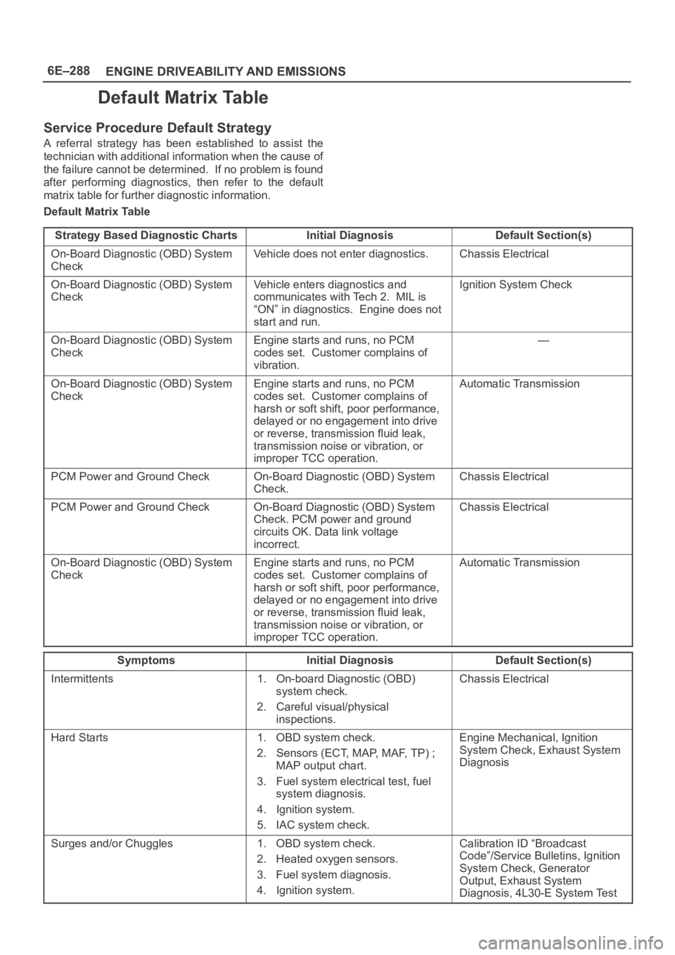
Default Matrix Table
Service Procedure Default Strategy
A referral strategy has been established to assist the
technician with additional information when the cause of
the failure cannot be determined. If no problem is found
after performing diagnostics, then refer to the default
matrix table for further diagnostic information.
Default Matrix Table
Strategy Based Diagnostic Charts
Initial DiagnosisDefault Section(s)
On-Board Diagnostic (OBD) System
CheckVehicle does not enter diagnostics.Chassis Electrical
On-Board Diagnostic (OBD) System
CheckVehicle enters diagnostics and
communicates with Tech 2. MIL is
“ON” in diagnostics. Engine does not
start and run.Ignition System Check
On-Board Diagnostic (OBD) System
CheckEngine starts and runs, no PCM
codes set. Customer complains of
vibration.—
On-Board Diagnostic (OBD) System
CheckEngine starts and runs, no PCM
codes set. Customer complains of
harsh or soft shift, poor performance,
delayed or no engagement into drive
or reverse, transmission fluid leak,
transmission noise or vibration, or
improper TCC operation.Automatic Transmission
PCM Power and Ground CheckOn-Board Diagnostic (OBD) System
Check.Chassis Electrical
PCM Power and Ground CheckOn-Board Diagnostic (OBD) System
Check. PCM power and ground
circuits OK. Data link voltage
incorrect.Chassis Electrical
On-Board Diagnostic (OBD) System
CheckEngine starts and runs, no PCM
codes set. Customer complains of
harsh or soft shift, poor performance,
delayed or no engagement into drive
or reverse, transmission fluid leak,
transmission noise or vibration, or
improper TCC operation.Automatic Transmission
SymptomsInitial DiagnosisDefault Section(s)
Intermittents1. On-board Diagnostic (OBD)
system check.
2. Careful visual/physical
inspections.Chassis Electrical
Hard Starts1. OBD system check.
2. Sensors (ECT, MAP, MAF, TP) ;
MAP output chart.
3. Fuel system electrical test, fuel
system diagnosis.
4. Ignition system.
5. IAC system check.Engine Mechanical, Ignition
System Check, Exhaust System
Diagnosis
Surges and/or Chuggles1. OBD system check.
2. Heated oxygen sensors.
3. Fuel system diagnosis.
4. Ignition system.Calibration ID “Broadcast
Code”/Service Bulletins, Ignition
System Check, Generator
Output, Exhaust System
Diagnosis, 4L30-E System Test
Page 1457 of 6000
6E–340
ENGINE DRIVEABILITY AND EMISSIONS
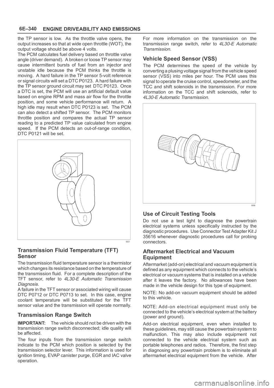
the TP sensor is low. As the throttle valve opens, the
output increases so that at wide open throttle (WOT), the
output voltage should be above 4 volts.
The PCM calculates fuel delivery based on throttle valve
angle (driver demand). A broken or loose TP sensor may
cause intermittent bursts of fuel from an injector and
unstable idle because the PCM thinks the throttle is
moving. A hard failure in the TP sensor 5-volt reference
or signal circuits will set a DTC P0123. A hard failure with
the TP sensor ground circuit may set DTC P0123. Once
a DTC is set, the PCM will use an artificial default value
based on engine RPM and mass air flow for the throttle
position, and some vehicle performance will return. A
high idle may result when DTC P0123 is set. The PCM
can also detect a shifted TP sensor. The PCM monitors
throttle position and compares the actual TP sensor
reading to a predicted TP value calculated from engine
speed. If the PCM detects an out-of-range condition,
DTC P0121 will be set.
0021
Transmission Fluid Temperature (TFT)
Sensor
The transmission fluid temperature sensor is a thermistor
which changes its resistance based on the temperature of
the transmission fluid. For a complete description of the
TFT sensor, refer to
4L30-E Automatic Transmission
Diagnosis
.
A failure in the TFT sensor or associated wiring will cause
DTC P0712 or DTC P0713 to set. In this case, engine
coolant temperature will be substituted for the TFT
sensor value and the transmission will operate normally.
Transmission Range Switch
IMPORTANT:The vehicle should not be driven with the
transmission range switch disconnected; idle quality will
be affected.
The four inputs from the transmission range switch
indicate to the PCM which position is selected by the
transmission selector lever. This information is used for
ignition timing, EVAP canister purge, EGR and IAC valve
operation.For more information on the transmission on the
transmission range switch, refer to
4L30-E Automatic
Transmission
.
Vehicle Speed Sensor (VSS)
The PCM determines the speed of the vehicle by
converting a plusing voltage signal from the vehicle speed
sensor (VSS) into miles per hour. The PCM uses this
signal to operate the cruise control, speedometer, and the
TCC and shift solenoids in the transmission. For more
information on the TCC and shift solenoids, refer to
4L30-E Automatic Transmission.
0008
Use of Circuit Testing Tools
Do not use a test light to diagnose the powertrain
electrical systems unless specifically instructed by the
diagnostic procedures. Use Connector Test Adapter Kit J
35616 whenever diagnostic procedures call for probing
connectors.
Aftermarket Electrical and Vacuum
Equipment
Aftermarket (add-on) electrical and vacuum equipment is
defined as any equipment which connects to the vehicle’s
electrical or vacuum systems that is installed on a vehicle
after it leaves the factory. No allowances have been
made in the vehicle design for this type of equipment.
NOTE: No add-on vacuum equipment should be added
to this vehicle.
NOTE: Add-on electrical equipment must only be
connected to the vehicle’s electrical system at the battery
(power and ground).
Add-on electrical equipment, even when installed to
these guidelines, may still cause the powertrain system to
malfunction. This may also include equipment not
connected to the vehicle electrical system such as
portable telephones and radios. Therefore, the first step
in diagnosing any powertrain problem is to eliminate all
aftermarket electrical equipment from the vehicle. After
Page 1870 of 6000

ENGINE ELECTRICAL 6D – 3
ON-VEHICLE SERVICE
BATTERY CHARGING
Observe the following safety precautions when
charging the battery:
1. Never attempt to charge the battery when the fluid
level is below the lower level line on the side of the
battery. In this case, the battery must be replaced.
2. Pay close attention to the battery during the
charging procedure.
Battery charging should be discontinued or the rate
of charge reduced if the battery feels hot to the
touch.
Battery charging should be discontinued or the rate
of charge reduced if the battery begins to gas or
spew electrolyte from the vent holes.
3. In order to more easily view the hydrometer blue
dot or ring, it may be necessary to jiggle or tilt the
battery.
4. Battery temperature can have a great effect on
battery charging capacity.
5. The sealed battery used on this vehicle may be
either quick-charged or slow-charged in the same
manner as other batteries.
Whichever method you decide to use, be sure that
you completely charge the battery. Never partially
charge the battery.
JUMP STARTING
JUMP STARTING WITH AN AUXILIARY
(BOOSTER) BATTERY
CAUTION: Never push or tow the vehicle in an
attempt to start it. Serious damage to the emission
system as well as other vehicle parts will result.
Treat both the discharged battery and the booster
battery with great care when using jumper cables.
Carefully follow the jump starting procedure, being
careful at all times to avoid sparking.
WARNING: Failure to carefully follow the jump
starting procedure could result in the following:
1. Serious personal injury, particularly to your
eyes.
2. Property damage from a battery explosion,
battery acid, or an electrical fire.
3. Damage to the electronic components of one or
both vehicles.
Never expose the battery to an open flame or electrical
spark. Gas generated by the battery may catch fire or
explode. Remove any rings, watches, or other jewelry
before working around the battery. Protect your eyes by
wearing an approved set of goggles.
Never allow battery fluid to come in contact with your
eyes or skin.
Never allow battery fluid to come in contact with fabrics
or painted surfaces.
Battery fluid is a highly corrosive acid.Should battery fluid come in contact with your eyes,
skin, fabric, or a painted surface, immediately and
thoroughly rinse the affected area with clean tap water.
Never allow metal tools or jumper cables to come in
contact with the positive battery terminal, or any other
metal surface of the vehicle. This will protect against a
short circuit.
Always keep batteries out of the reach of young
children.
JUMP STARTING PROCEDURE
1. Set the vehicle parking brake.
If the vehicle is equipped with an automatic
transmission, place the selector lever in the “PARK”
position.
If the vehicle is equipped with a manual
transmission place the shift lever in the “NEUTRAL”
position.
Turn “OFF” the ignition.
Turn “OFF” all lights and any other accessory
requiring electrical power.
2. Look at the built-in hydrometer.
If the indication area of the built-in hydrometer is
completely clear, do not try to jump start.
3. Attach the end of one jumper cable to the positive
terminal of the booster battery.
Attach the other end of the same cable to the
positive terminal of the discharged battery.
Do not allow the vehicles to touch each other.
This will cause a ground connection, effectively
neutralizing the charging procedure.
Be sure that the booster battery has a 12 volt rating.
4. Attach one end of the remaining cable to the
negative terminal of the booster battery.
Attach the other end of the same cable to a solid
engine ground (such as the A/C compressor
bracket or the generator mounting bracket) of the
vehicle with the discharged battery.
This ground connection must be at least 450 mm
(18 in) from the battery of the vehicle whose battery
is being charged.
WARNING: Never attach the end of the jumper
cable directly to the negative terminal of the dead
battery.
5. Start the engine of the vehicle with the good battery.
Make sure that all unnecessary electrical
accessories have been turned “OFF”.
6. Start the engine of the vehicle with the dead battery.
7. To remove the jumper cables, follow the above
directions in the reverse order.
Be sure to first disconnect the negative cable from
the vehicle with the discharged battery.
Page 1949 of 6000
6E–56
4JX1–TC ENGINE DRIVEABILITY AND EMISSIONS
Diagnostic Trouble Code (DTC) P0107 (Flash DTC 34)
MAP Sensor Circuit Low Voltage
060RW134
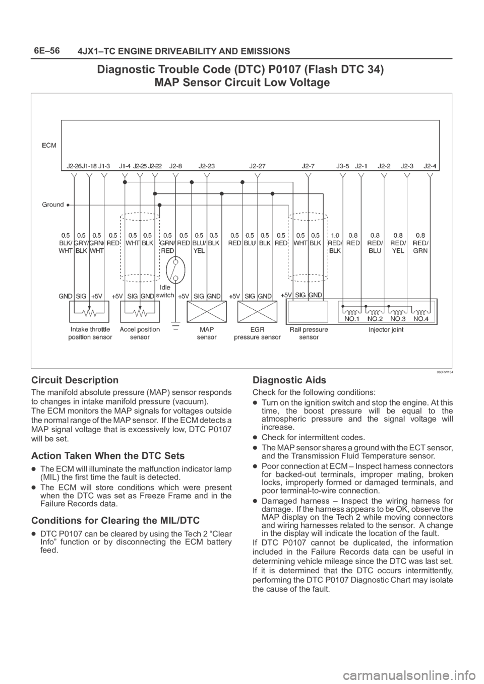
Circuit Description
The manifold absolute pressure (MAP) sensor responds
to changes in intake manifold pressure (vacuum).
The ECM monitors the MAP signals for voltages outside
the normal range of the MAP sensor. If the ECM detects a
MAP signal voltage that is excessively low, DTC P0107
will be set.
Action Taken When the DTC Sets
The ECM will illuminate the malfunction indicator lamp
(MIL) the first time the fault is detected.
The ECM will store conditions which were present
when the DTC was set as Freeze Frame and in the
Failure Records data.
Conditions for Clearing the MIL/DTC
DTC P0107 can be cleared by using the Tech 2 “Clear
Info” function or by disconnecting the ECM battery
feed.
Diagnostic Aids
Check for the following conditions:
Turn on the ignition switch and stop the engine. At this
time, the boost pressure will be equal to the
atmospheric pressure and the signal voltage will
increase.
Check for intermittent codes.
The MAP sensor shares a ground with the ECT sensor,
and the Transmission Fluid Temperature sensor.
Poor connection at ECM – Inspect harness connectors
for backed-out terminals, improper mating, broken
locks, improperly formed or damaged terminals, and
poor terminal-to-wire connection.
Damaged harness – Inspect the wiring harness for
damage. If the harness appears to be OK, observe the
MAP display on the Tech 2 while moving connectors
and wiring harnesses related to the sensor. A change
in the display will indicate the location of the fault.
If DTC P0107 cannot be duplicated, the information
included in the Failure Records data can be useful in
determining vehicle mileage since the DTC was last set.
If it is determined that the DTC occurs intermittently,
performing the DTC P0107 Diagnostic Chart may isolate
the cause of the fault.
Page 2092 of 6000
6E–199 4JX1–TC ENGINE DRIVEABILITY AND EMISSIONS
Default Matrix Table
Service Procedure Default Strategy
A referral strategy has been established to assist the
technician with additional information when the cause ofthe failure cannot be determined. If no problem is found
after performing diagnostics, then refer to the default
matrix table for further diagnostic information.
Default Matrix Table
Strategy Based Diagnostic ChartsInitial DiagnosisDefault Section(s)
On-Board Diagnostic (OBD) System
CheckVehicle does not enter diagnostics.Chassis Electrical
On-Board Diagnostic (OBD) System
CheckVehicle enters diagnostics and
communicates with the Tech 2. MIL is
“ON” in diagnostics. Engine does not
start and run.HEUI System Check
On-Board Diagnostic (OBD) System
CheckEngine starts and runs, no ECM codes
set. Customer complains of vibration.—
On-Board Diagnostic (OBD) System
CheckEngine starts and runs, no ECM codes
set. Customer complains of harsh or
soft shift, poor performance, delayed or
no engagement into drive or reverse,
transmission fluid leak, transmission
noise or vibration, or improper TCC
operation.Automatic Transmission
ECM Power and Ground CheckOn-Board Diagnostic (OBD) System
Check.Chassis Electrical
ECM Power and Ground CheckOn-Board Diagnostic (OBD) System
Check. ECM power and ground circuits
OK. Data link voltage incorrect.Chassis Electrical
On-Board Diagnostic (OBD) System
CheckEngine starts and runs, no ECM codes
set. Customer complains of harsh or
soft shift, poor performance, delayed or
no engagement into drive or reverse,
transmission fluid leak, transmission
noise or vibration, or improper TCC
operation.Automatic Transmission
SymptomsInitial DiagnosisDefault Section(s)
Intermittents1. On-board diagnostic (OBD)
system check.
2. Careful visual/physical inspections.Chassis Electrical
Hard Starts1. OBD system check.
2. Sensors (ECT, MAP, EGR, AP) ;
output chart.
3. Fuel system electrical test, fuel
system diagnosis.
4. Injector system.Engine Mechanical, Injector
System Check, Exhaust System
Diagnosis
Surges and/or Chuggles1. OBD system check.
2. Fuel system diagnosis.
3. Injector system.Calibration ID “Broadcast”
/Service Bulletins, Ignition
System Check, Generator
Output, Exhaust System
Diagnosis
Lack of Power, Sluggish or Spongy1. OBD system check.
2. Fuel system diagnosis.
3. Injector system.Refer to Exhaust System in
Engine Exhaust, TCC
Operation, Calibration
ID/Service Bulletins