1998 OPEL FRONTERA oil temperature
[x] Cancel search: oil temperaturePage 1793 of 6000

6A – 60 ENGINE MECHANICAL
VALVE STEM SEAL, VALVE SPRING AND ADJUSTER
REMOVAL
1. Disconnect battery ground cable.
2. Drain engine coolant.
3. Remove the air duct from between air cleaner and
turbocharger.
4. Remove intercooler assembly.
Refer to “Intercooler” in this manual.
5. Remove oil level gauge guide assembly.
6. Disconnect PCV hose.
7. Disconnect EGR vacuum hose.
8. Disconnect harness connectors around the cylinder
head such as the injector, CMP sensor, MAP
sensor, EGR sensor, EVRV, IAT sensor, A/C
compressor, TP stepping motor, TP sensor and fuel
temperature sensor etc.
9. Remove A/C compressor assembly.
10. Remove A/C compressor bracket.
11. Remove generator assembly and take out drivebelt.
12. Remove heat protector, remove exhaust valve
assembly.
13. Remove water cooling hose and lubrication pipe for
turbocharger.
14. Remove turbocharger assembly.
15. Remove hose between thermostat and radiator.
16. Remove noise insulator cover of cylinder head.
NOTE: Do not damage injector harness.
17. Remove high pressure oil pipe.
18. Remove timing belt cover.
19. Remove CMP sensor bracket.
20. Remove timing belt tensioner then remove timing
belt.
21. Remove camshaft pulley.
22. Remove front plate.
23. Remove engine coolant pipe between cylinder
head and water pump.
1
2
3
4
5
6
9
10
7
8
011RW031
Legend
(1) Adjuster
(2) Tappet
(3) Split Collar
(4) Spring Seat Upper
(5) Valve Spring(6) Spring Seat Lower
(7) Valve Stem Seal
(8) Valve Guide
(9) Valve Seat
(10) Valve
Page 1794 of 6000
ENGINE MECHANICAL 6A – 61
24. Remove fuel pipe between fuel pump and intake
manifold.
25. Remove fuel return pipe from rear of cylinder head.
26. Remove intake manifold assembly.
27. Disconnect glow plug harness and remove glow
plug.
28. Remove cylinder head cover.
29. Remove injector harness connector.
30. Disconnect harness connector from oil pressure
sensor and oil temperature sensor on the oil rail.
31. Remove injector harness assembly.
32. Remove injector clamp.
33. Remove injector is fixed bolts.
34. Remove injector assembly.
35. Remove oil rail.
36. Remove camshaft carrier assembly with camshaft.
37. Remove cylinder head assembly.
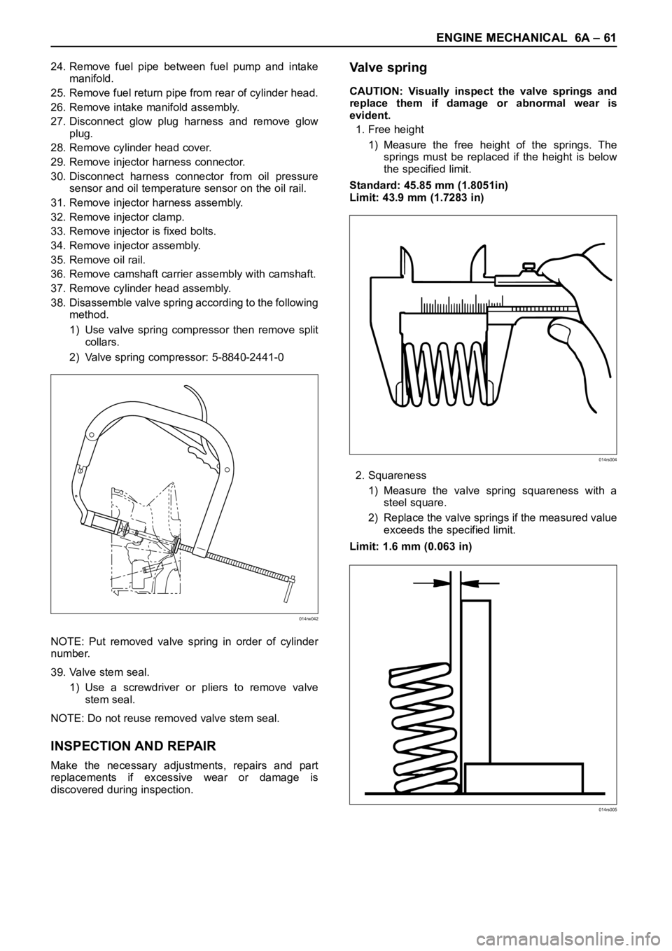
38. Disassemble valve spring according to the following
method.
1) Use valve spring compressor then remove split
collars.
2) Valve spring compressor: 5-8840-2441-0
NOTE: Put removed valve spring in order of cylinder
number.
39. Valve stem seal.
1) Use a screwdriver or pliers to remove valve
stem seal.
NOTE: Do not reuse removed valve stem seal.
INSPECTION AND REPAIR
Make the necessary adjustments, repairs and part
replacements if excessive wear or damage is
discovered during inspection.
Va l v e s p r i n g
CAUTION: Visually inspect the valve springs and
replace them if damage or abnormal wear is
evident.
1. Free height
1) Measure the free height of the springs. The
springs must be replaced if the height is below
the specified limit.
Standard: 45.85 mm (1.8051in)
Limit: 43.9 mm (1.7283 in)
2. Squareness
1) Measure the valve spring squareness with a
steel square.
2) Replace the valve springs if the measured value
exceeds the specified limit.
Limit: 1.6 mm (0.063 in)
014rw042
014rs004
014rs005
Page 1799 of 6000
6A – 66 ENGINE MECHANICAL
INSTALLATION
1. Valve stem seal
1) Use the special tool to install the stem seal to the
valve guide.
Stem Seal Installer: 5-8840-2033-0
2. Valve spring.
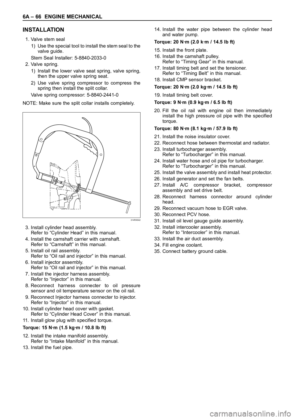
1) Install the lower valve seat spring, valve spring,
then the upper valve spring seat.
2) Use valve spring compressor to compress the
spring then install the split collar.
Valve spring compressor: 5-8840-2441-0
NOTE: Make sure the split collar installs completely.
3. Install cylinder head assembly.
Refer to “Cylinder Head” in this manual.
4. Install the camshaft carrier with camshaft.
Refer to “Camshaft” in this manual.
5. Install oil rail assembly.
Refer to “Oil rail and injector” in this manual.
6. Install injector assembly.
Refer to “Oil rail and injector” in this manual.
7. Install the injector harness assembly.
Refer to “Injector” in this manual.
8. Reconnect harness connecter to oil pressure
sensor and oil temperature sensor on the oil rail.
9. Reconnect Injector harness connecter to injector.
Refer to “Injector” in this manual.
10. Install cylinder head cover with gasket.
Refer to “Cylinder Head Cover” in this manual.
11. Install glow plug with specified torque.
Torque: 15 Nꞏm (1.5 kgꞏm / 10.8 lb ft)
12. Install the intake manifold assembly.
Refer to “Intake Manifold” in this manual.
13. Install the fuel pipe.14. Install the water pipe between the cylinder head
and water pump.
Torque: 20 Nꞏm (2.0 kꞏm / 14.5 lb ft)
15. Install the front plate.
16. Install the camshaft pulley.
Refer to “Timing Gear” in this manual.
17. Install timing belt and set the tensioner.
Refer to “Timing Belt” in this manual.
18. Install CMP sensor bracket.
Torque: 20 Nꞏm (2.0 kgꞏm / 14.5 lb ft)
19. Install timing belt cover.
Torque: 9 Nꞏm (0.9 kgꞏm / 6.5 lb ft)
20. Fill the oil rail with engine oil then immediately
install the high pressure oil pipe with the specified
torque.
Torque: 80 Nꞏm (8.1 kgꞏm / 57.9 lb ft)
21. Install the noise insulator cover.
22. Reconnect hose between thermostat and radiator.
23. Install turbocharger assembly.
Refer to “Turbocharger” in this manual.
24. Install water hose and oil pipe for turbocharger.
Refer to “Turbocharger” in this manual.
25. Install the valve assembly and install heat protector.
26. Install generator and set the fan belts.
27. Install A/C compressor bracket, compressor
assembly and set drive belt.
28. Reconnect harness connector around cylinder
head.
29. Reconnect vacuum hose to EGR valve.
30. Reconnect PCV hose.
31. Install oil level gauge guide assembly.
32. Install intercooler assembly.
Refer to “Intercooler” in this manual.
33. Install the air duct assembly.
34. Fill engine coolant.
35. Connect battery ground cable.
014RW042
Page 1838 of 6000

ENGINE COOLING 6B – 5
ENGINE COOLANT CHANGE
PROCEDURE
1. To change engine coolant, make sure that the
engine is cool.
WARNING:
When the coolant is heated to a high temperature,
be sure not to loosen or remove the radiator cap.
Otherwise you might get scalded by hot vapor or
boiling water. To open the radiator cap, put a piece
of thick cloth on the cap and loosen the cap slowly
to reduce the pressure once the coolant has
become cooler.
2. Open radiator cap and drain the cooling system by
loosening the drain valve on the radiator and on the
cylinder body.
NOTE: For best results it is suggested that the engine
cooling system be flushed at least once a year. It is
advisable to flush the interior of the cooling system
including the radiator before using anti-freeze
(ethylene-glycol based).
Replace damaged rubber hoses as the engine anti-
freeze coolant is liable to leak out even minor cracks.
Isuzu recommends using Isuzu genuine anti-freeze
(ethylene-glycol based) or equivalent, for the cooling
system and not add any inhibitors or additives.
CAUTION:
A failure to correctly fill the engine cooling system
in changing or topping off coolant may sometimes
cause the coolant to overflow from the filler neck
even before the engine and radiator are completely
full.
If the engine runs under this condition, shortage of
coolant may possibly result in engine overheating.
To avoid such trouble, the following precautions
should be taken in filling the system.
3. To refill engine coolant, pour coolant up to filler neck
using a filling hose which is smaller in outside
diameter than the filler neck. Otherwise air between
the filler neck and the filling hose will block entry,
preventing the system from completely filling up.
4. Keep a filling rate of 9 liter/min. or less. Filling over
this maximum rate may force air inside the engine
and radiator.
And also, the coolant overflow will increase, making
it difficult to determine whether or not the system is
completely full.
5. After filling the system full, pull out the filling hose
and check to see if air trapped in the system is
dislodged and the coolant level goes down. Should
the coolant level go down, repeat topping-off until
there is no more drop in the coolant level.
6. Directly after filling the radiator, fill the reservoir to
the maximum level.
7. Install and tighten radiator cap and start the engine.
After idling for 2 to 3 minutes, stop the engine and
reopen radiator cap. If the water level is lower,
replenish.WARNING:
When the coolant is heated to a high temperature,
be sure not to loosen or remove the radiator cap.
Otherwise you might get scalded by hot vapor or
boiling water. To open the radiator cap, put a piece
of thick cloth on the cap and loosen the cap slowly
to reduce the pressure once the coolant has
become cooler.
8. After tightening radiator cap, warm up the engine at
about 2,000 rpm.
Set heater adjustment to the highest temperature
position, and let the coolant circulate also into
heater water system.
9. Check to see the thermostat has opened by the
needle position of a water thermometer, conduct a
5-minute idle again and stop the engine.
10. When the engine has been cooled, check filler neck
for water level and replenish if required. Should
extreme shortage of coolant be found, check the
coolant system and reservoir tank hose for leakage.
11. Fill the coolant into the reservoir tank up to “MAX”
line.
Page 1850 of 6000

ENGINE FUEL 6C – 5
FUEL FILTER
Legend
(1) Priming Pump
(2) Fuel Filter Cartridge
A cartridge type fuel filter is used along with the piston
type fuel pump on the high pressure oil pump.
The fuel filter removes foreign material from the fuel
before it reaches the fuel pump.
A diaphragm type priming pump is installed at the top of
the fuel filter. It is used during the air bleeding
procedures.
INJECTOR ASSEMBLY
Legend
(1) Oil Passage
(2) Fuel Passage
1. Construction of Fuel Injector
The fuel injector is comprised of the solenoid
section, hydraulic line, and fuel line. Fuel injection is
controlled by the continuity time signal and
continuity start timing signal sent by the ECM
(Electronic Control Module) to the solenoid.
2. Working of Fuel Injector
1) The ECM detects the working of the engine from
its input signals, such as engine speed
accelerator throttle opening, and engine coolant
temperature, sending the optimal signals to the
solenoid.
1
2
041RW017
1
2
055RW018
Page 1896 of 6000
6E–3 4JX1–TC ENGINE DRIVEABILITY AND EMISSIONS
Action Taken When the DTC Sets 6E–90. . . . . . .
Conditions for Clearing the MIL/DTC 6E–90. . . . .
Diagnostic Aids 6E–90. . . . . . . . . . . . . . . . . . . . . . . .
Diagnostic Trouble Code (DTC) P1196
(Flash DTC 62) Rail Pressure System
High Warning 6E–92. . . . . . . . . . . . . . . . . . . . . . . . . .
Circuit Description 6E–93. . . . . . . . . . . . . . . . . . . . .
Action Taken When the DTC Sets 6E–93. . . . . . .
Conditions for Clearing the MIL/DTC 6E–93. . . . .
Diagnostic Aids 6E–93. . . . . . . . . . . . . . . . . . . . . . . .
Test Description 6E–93. . . . . . . . . . . . . . . . . . . . . . .
Diagnostic Trouble Code (DTC) P0197
(Flash DTC 16) Oil Temp Sensor Low
Voltage 6E–94. . . . . . . . . . . . . . . . . . . . . . . . . . . . . . . .
Circuit Description 6E–94. . . . . . . . . . . . . . . . . . . . .
Action Taken When the DTC Sets 6E–94. . . . . . .
Conditions for Clearing the MIL/DTC 6E–94. . . . .
Diagnostic Aids 6E–94. . . . . . . . . . . . . . . . . . . . . . . .
Test Description 6E–95. . . . . . . . . . . . . . . . . . . . . . .
Engine Oil Temperature Sensor 6E–95. . . . . . . . .
Diagnostic Trouble Code (DTC) P0198
(Flash DTC 16) Oil Temp Sensor High
Voltage 6E–96. . . . . . . . . . . . . . . . . . . . . . . . . . . . . . . .
Circuit Description 6E–96. . . . . . . . . . . . . . . . . . . . .
Action Taken When the DTC Sets 6E–96. . . . . . .
Conditions for Clearing the MIL/DTC 6E–96. . . . .
Diagnostic Aids 6E–96. . . . . . . . . . . . . . . . . . . . . . . .
Test Description 6E–97. . . . . . . . . . . . . . . . . . . . . . .
Engine Oil Temperature Sensor 6E–97. . . . . . . . .
Diagnostic Trouble Code (DTC) P0201
(Flash DTC 51) Injector # 1 Circuit Fault 6E–99. . .
Circuit Description 6E–99. . . . . . . . . . . . . . . . . . . . .
Action Taken When the DTC Sets 6E–99. . . . . . .
Conditions for Clearing the MIL/DTC 6E–99. . . . .
Diagnostic Aids 6E–99. . . . . . . . . . . . . . . . . . . . . . . .
Test Description 6E–99. . . . . . . . . . . . . . . . . . . . . . .
Injector Test 6E–99. . . . . . . . . . . . . . . . . . . . . . . . . .
Diagnostic Trouble Code (DTC) P0202
(Flash DTC 52) Injector # 2 Circuit Fault 6E–101. . .
Circuit Description 6E–101. . . . . . . . . . . . . . . . . . . . .
Action Taken When the DTC Sets 6E–101. . . . . . .
Conditions for Clearing the MIL/DTC 6E–101. . . . .
Diagnostic Aids 6E–101. . . . . . . . . . . . . . . . . . . . . . . .
Test Description 6E–101. . . . . . . . . . . . . . . . . . . . . . .
Injector Test 6E–101. . . . . . . . . . . . . . . . . . . . . . . . . .
Diagnostic Trouble Code (DTC) P0203
(Flash DTC 52) Injector # 3 Circuit Fault 6E–103. . .
Circuit Description 6E–103. . . . . . . . . . . . . . . . . . . . .
Action Taken When the DTC Sets 6E–103. . . . . . .
Conditions for Clearing the MIL/DTC 6E–103. . . . .
Diagnostic Aids 6E–103. . . . . . . . . . . . . . . . . . . . . . . .
Test Description 6E–103. . . . . . . . . . . . . . . . . . . . . . .
Injector Test 6E–103. . . . . . . . . . . . . . . . . . . . . . . . . . Diagnostic Trouble Code (DTC) P0204
(Flash DTC 54) Injector # 4 Circuit Fault 6E–105
. . .
Circuit Description 6E–105. . . . . . . . . . . . . . . . . . . . .
Action Taken When the DTC Sets 6E–105. . . . . . .
Conditions for Clearing the MIL/DTC 6E–105. . . . .
Diagnostic Aids 6E–105. . . . . . . . . . . . . . . . . . . . . . . .
Test Description 6E–105. . . . . . . . . . . . . . . . . . . . . . .
Injector Test 6E–105. . . . . . . . . . . . . . . . . . . . . . . . . .
Diagnostic Trouble Code (DTC) P0217
(Flash DTC 22) High Coolant Temp Waring 6E–107
Circuit Description 6E–107. . . . . . . . . . . . . . . . . . . . .
Action Taken When the DTC Sets 6E–107. . . . . . .
Conditions for Clearing the MIL/DTC 6E–107. . . . .
Diagnostic Aids 6E–107. . . . . . . . . . . . . . . . . . . . . . . .
Test Description 6E–107. . . . . . . . . . . . . . . . . . . . . . .
Diagnostic Trouble Code (DTC) P1217
(Flash DTC 36) High Oil Temp Warning 6E–109. . . .
Circuit Description 6E–109. . . . . . . . . . . . . . . . . . . . .
Action Taken When the DTC Sets 6E–109. . . . . . .
Conditions for Clearing the MIL/DTC 6E–109. . . . .
Diagnostic Aids 6E–109. . . . . . . . . . . . . . . . . . . . . . . .
Diagnostic Trouble Code (DTC) P0219
(Flash DTC 11) Engine Over Speed Warning 6E–111
Circuit Description 6E–111. . . . . . . . . . . . . . . . . . . . .
Action Taken When the DTC Sets 6E–111. . . . . . .
Conditions for Clearing the MIL/DTC 6E–111. . . . .
Diagnostic Aids 6E–111. . . . . . . . . . . . . . . . . . . . . . . .
Diagnostic Trouble Code (DTC) P0336
(Flash DTC 43) CKP (Crank Position)
Sensor Out of Synchro 6E–114. . . . . . . . . . . . . . . . . .
Circuit Description 6E–114. . . . . . . . . . . . . . . . . . . . .
Action Taken When the DTC Sets 6E–114. . . . . . .
Conditions for Clearing the MIL/DTC 6E–114. . . . .
Diagnostic Aids 6E–114. . . . . . . . . . . . . . . . . . . . . . . .
Diagnostic Trouble Code (DTC) P0337
(Flash DTC 43) CKP (Crank Position)
Sensor No Signal 6E–116. . . . . . . . . . . . . . . . . . . . . . .
Circuit Description 6E–116. . . . . . . . . . . . . . . . . . . . .
Action Taken When the DTC Sets 6E–116. . . . . . .
Conditions for Clearing the MIL/DTC 6E–116. . . . .
Diagnostic Aids 6E–116. . . . . . . . . . . . . . . . . . . . . . . .
Diagnostic Trouble Code (DTC) P0341
(Flash DTC 41) CMP (Cam Position)
Sensor Out of Synchro 6E–119. . . . . . . . . . . . . . . . . .
Circuit Description 6E–119. . . . . . . . . . . . . . . . . . . . .
Action Taken When the DTC Sets 6E–119. . . . . . .
Conditions for Clearing the MIL/DTC 6E–119. . . . .
Diagnostic Aids 6E–119. . . . . . . . . . . . . . . . . . . . . . . .
Test Description 6E–119. . . . . . . . . . . . . . . . . . . . . . .
Diagnostic Trouble Code (DTC) P0342
(Flash DTC 41) CMP (Cam Position)
Sensor No Signal 6E–122. . . . . . . . . . . . . . . . . . . . . . .
Circuit Description 6E–122. . . . . . . . . . . . . . . . . . . . .
Action Taken When the DTC Sets 6E–122. . . . . . .
Conditions for Clearing the MIL/DTC 6E–122. . . . .
Page 1898 of 6000
6E–5 4JX1–TC ENGINE DRIVEABILITY AND EMISSIONS
Conditions for Clearing the MIL/DTC 6E–159. . . . .
Diagnostic Aids 6E–159. . . . . . . . . . . . . . . . . . . . . . . .
Diagnostic Trouble Code (DTC) P1562
(Flash DTC 35) System Voltage Too Low
at Cranking 6E–160. . . . . . . . . . . . . . . . . . . . . . . . . . . .
Circuit Description 6E–160. . . . . . . . . . . . . . . . . . . . .
Action Taken When the DTC Sets 6E–160. . . . . . .
Conditions for Clearing the MIL/DTC 6E–160. . . . .
Diagnostic Aids 6E–160. . . . . . . . . . . . . . . . . . . . . . . .
Diagnostic Trouble Code (DTC) P1587
(Flash DTC 25) Brake SW Malfunction 6E–161. . . .
Circuit Description 6E–161. . . . . . . . . . . . . . . . . . . . .
Action Taken When the DTC Sets 6E–161. . . . . . .
Conditions for Clearing the MIL/DTC 6E–161. . . . .
Diagnostic Aids 6E–161. . . . . . . . . . . . . . . . . . . . . . . .
Diagnostic Trouble Code (DTC) P1588
(Flash DTC 25) Brake SW Malfunction 6E–163. . . .
Circuit Description 6E–163. . . . . . . . . . . . . . . . . . . . .
Action Taken When the DTC Sets 6E–163. . . . . . .
Conditions for Clearing the MIL/DTC 6E–163. . . . .
Diagnostic Aids 6E–163. . . . . . . . . . . . . . . . . . . . . . . .
Diagnostic Trouble Code (DTC) P0601
(Flash DTC 55) ECM Checksum Error 6E–165. . . . .
Action Taken When the DTC Sets 6E–165. . . . . . .
Conditions for Clearing the MIL/DTC 6E–165. . . . .
Diagnostic Aids 6E–165. . . . . . . . . . . . . . . . . . . . . . . .
Diagnostic Trouble Code (DTC) P0650
(Flash DTC 77) Check Engine Lam Circuit
Open/Short 6E–166. . . . . . . . . . . . . . . . . . . . . . . . . . . .
Circuit Description 6E–166. . . . . . . . . . . . . . . . . . . . .
Action Taken When the DTC Sets 6E–166. . . . . . .
Conditions for Clearing the MIL/DTC 6E–166. . . . .
Diagnostic Aids 6E–166. . . . . . . . . . . . . . . . . . . . . . . .
Diagnostic Trouble Code (DTC) P0654
(Flash DTC 27) Tachometer Circuit
Open/Short 6E–168. . . . . . . . . . . . . . . . . . . . . . . . . . . .
Circuit Description 6E–168. . . . . . . . . . . . . . . . . . . . .
Action Taken When the DTC Sets 6E–168. . . . . . .
Conditions for Clearing the MIL/DTC 6E–168. . . . .
Diagnostic Aids 6E–168. . . . . . . . . . . . . . . . . . . . . . . .
Diagnostic Trouble Code (DTC) P1655
(Flash DTC 17) Thermo Relay Circuit
Open/Short 6E–170. . . . . . . . . . . . . . . . . . . . . . . . . . . .
Circuit Description 6E–170. . . . . . . . . . . . . . . . . . . . .
Action Taken When the DTC Sets 6E–170. . . . . . .
Conditions for Clearing the MIL/DTC 6E–170. . . . .
Diagnostic Aids 6E–170. . . . . . . . . . . . . . . . . . . . . . . .
Diagnostic Trouble Code (DTC) P1657
(Flash DTC 76) ECM Main Relay Circuit
Open/Short 6E–172. . . . . . . . . . . . . . . . . . . . . . . . . . . .
Circuit Description 6E–172. . . . . . . . . . . . . . . . . . . . .
Action Taken When the DTC Sets 6E–172. . . . . . .
Conditions for Clearing the MIL/DTC 6E–172. . . . .
Diagnostic Aids 6E–172. . . . . . . . . . . . . . . . . . . . . . . . Diagnostic Trouble Code (DTC) P1589
(Flash DTC 47) Transmission SW Circuit
Open/Short 6E–174. . . . . . . . . . . . . . . . . . . . . . . . . . . .
Circuit Description 6E–174. . . . . . . . . . . . . . . . . . . . .
Action Taken When the DTC Sets 6E–174. . . . . . .
Conditions for Clearing the MIL/DTC 6E–174. . . . .
Diagnostic Aids 6E–174. . . . . . . . . . . . . . . . . . . . . . . .
Symptom Diagnosis 6E–176. . . . . . . . . . . . . . . . . . . . .
Default Matrix Table 6E–199. . . . . . . . . . . . . . . . . . . . .
On–Vehicle Service Camshaft Position
(CMP) Sensor 6E–201. . . . . . . . . . . . . . . . . . . . . . . . . .
Removal Procedure 6E–201. . . . . . . . . . . . . . . . . . . .
Inspection Procedure 6E–201. . . . . . . . . . . . . . . . . .
Installation Procedure 6E–201. . . . . . . . . . . . . . . . . .
Crankshaft Position (CKP) Sensor 6E–202. . . . . . . . .
Removal Procedure 6E–202. . . . . . . . . . . . . . . . . . . .
Installation Procedure 6E–202. . . . . . . . . . . . . . . . . .
Engine Coolant Temperature (ECT) Sensor 6E–203.
Removal Procedure 6E–203. . . . . . . . . . . . . . . . . . . .
Installation Procedure 6E–203. . . . . . . . . . . . . . . . . .
Intake Air Temperature (IAT) Sensor 6E–203. . . . . . .
Removal Procedure 6E–203. . . . . . . . . . . . . . . . . . . .
Installation Procedure 6E–204. . . . . . . . . . . . . . . . . .
Manifold Absolute Pressure (MAP) Sensor 6E–204.
Removal Procedure 6E–204. . . . . . . . . . . . . . . . . . . .
Installation Procedure 6E–205. . . . . . . . . . . . . . . . . .
Oil Temperature (OT) Sensor 6E–205. . . . . . . . . . . . .
Removal Procedure 6E–205. . . . . . . . . . . . . . . . . . . .
Installation Procedure 6E–206. . . . . . . . . . . . . . . . . .
Malfunction Indicator Lamp (MIL) 6E–206. . . . . . . . . .
Removal and Installation Procedure 6E–206. . . . . .
Engine Control Module (ECM) 6E–206. . . . . . . . . . . .
Service Precaution 6E–206. . . . . . . . . . . . . . . . . . . .
Electrostatic Discharge (ESD) Damage 6E–206. . .
Removal Procedure 6E–207. . . . . . . . . . . . . . . . . . . .
Installation Procedure 6E–208. . . . . . . . . . . . . . . . . .
EEPROM 6E–208. . . . . . . . . . . . . . . . . . . . . . . . . . . . . .
General Description 6E–208. . . . . . . . . . . . . . . . . . . .
Functional Check 6E–208. . . . . . . . . . . . . . . . . . . . . .
Intake Throttle Position (ITP) Sensor 6E–208. . . . . . .
Removal Procedure 6E–208. . . . . . . . . . . . . . . . . . . .
Function Check 6E–209. . . . . . . . . . . . . . . . . . . . . . .
Installation Procedure 6E–209. . . . . . . . . . . . . . . . . .
Vehicle Speed Sensor (VSS) 6E–210. . . . . . . . . . . . .
Removal Procedure 6E–210. . . . . . . . . . . . . . . . . . . .
Inspection Procedure 6E–210. . . . . . . . . . . . . . . . . .
Installation Procedure 6E–210. . . . . . . . . . . . . . . . . .
Air Cleaner/Air Filter 6E–211. . . . . . . . . . . . . . . . . . . . .
Removal Procedure 6E–211. . . . . . . . . . . . . . . . . . . .
Installation Procedure 6E–211. . . . . . . . . . . . . . . . . .
Accel Position (AP) Sensor 6E–211. . . . . . . . . . . . . . .
Removal Procedure 6E–211. . . . . . . . . . . . . . . . . . . .
Installation Procedure 6E–212. . . . . . . . . . . . . . . . . .
Accelerator Pedal Replacement 6E–212. . . . . . . . . . .
Page 1900 of 6000
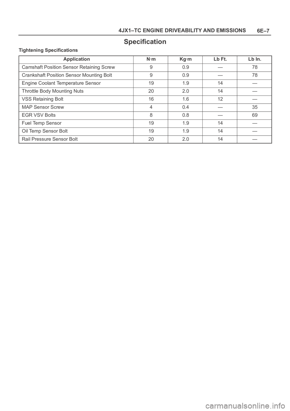
6E–7 4JX1–TC ENGINE DRIVEABILITY AND EMISSIONS
Specification
Tightening Specifications
Application
NꞏmKgꞏmLb Ft.Lb In.
Camshaft Position Sensor Retaining Screw90.9—78
Crankshaft Position Sensor Mounting Bolt90.9—78
Engine Coolant Temperature Sensor191.914—
Throttle Body Mounting Nuts202.014—
VSS Retaining Bolt161.612—
MAP Sensor Screw40.4—35
EGR VSV Bolts80.8—69
Fuel Temp Sensor191.914—
Oil Temp Sensor Bolt191.914—
Rail Pressure Sensor Bolt202.014—