Page 4015 of 6000
4A2B–8DIFFERENTIAL (REAR 244mm)
7.Remove the parking brake cable mounting
bolts(Behind the back plate)(1).
311RS001
8. Remove the bearing holder mounting nuts.
9. Remove axle shaft assembly.
NOTE: Be sure not to damage the oil seal.
10. Remove snap ring.
11. Using a bearing remover 5–8840–2295–0 and press,
remove retainer together with the bearing holder.
420RY00012
12. Remove bearing.
13. Remove bearing holder.
14. Remove back plate.15. Remove the wheel pins using a remover
5–8840–0029–0.
420RY00011
Inspection and Repair
Make necessary correction or parts replacement if wear,
corrosion or any other abnormal conditions are found
through inspection.
Visual Check:
Check the following parts for wear, damage, noise or any
other abnormal conditions:
1. Axle shaft
2. Bearing
When checking the axle shaft, pay special attention to the
splined portions and replace the shaft if distortion or step
wear is noticeable. Correct slight step wear with a grinder.
420RS008
Page 4018 of 6000
DIFFERENTIAL (REAR 244mm)
4A2B–11
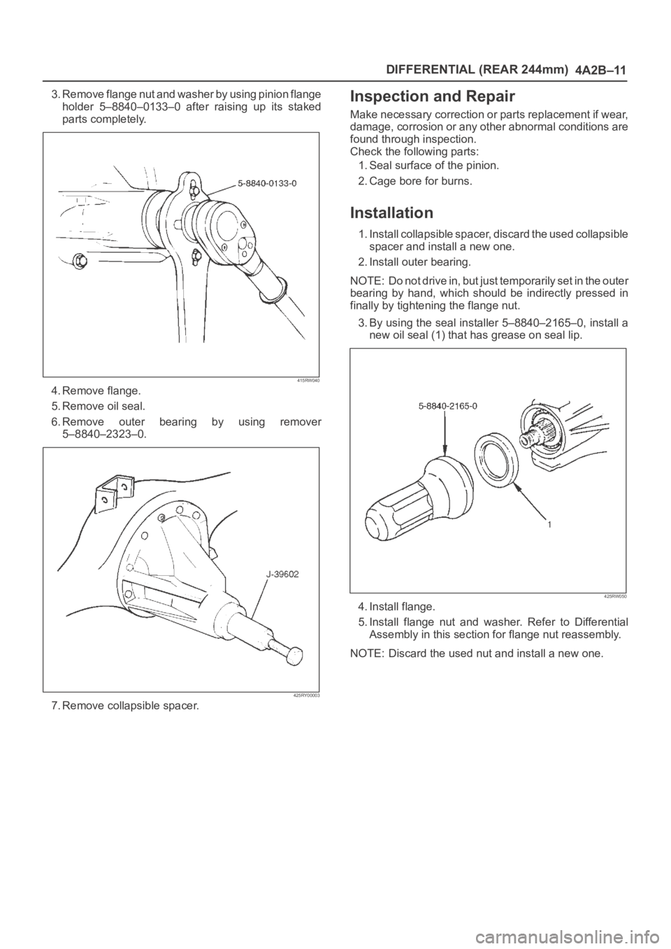
3. Remove flange nut and washer by using pinion flange
holder 5–8840–0133–0 after raising up its staked
parts completely.
415RW040
4. Remove flange.
5. Remove oil seal.
6. Remove outer bearing by using remover
5–8840–2323–0.
425RY00003
7. Remove collapsible spacer.
Inspection and Repair
Make necessary correction or parts replacement if wear,
damage, corrosion or any other abnormal conditions are
found through inspection.
Check the following parts:
1. Seal surface of the pinion.
2. Cage bore for burns.
Installation
1. Install collapsible spacer, discard the used collapsible
spacer and install a new one.
2. Install outer bearing.
NOTE: Do not drive in, but just temporarily set in the outer
bearing by hand, which should be indirectly pressed in
finally by tightening the flange nut.
3. By using the seal installer 5–8840–2165–0, install a
new oil seal (1) that has grease on seal lip.
425RW050
4. Install flange.
5. Install flange nut and washer. Refer to Differential
Assembly in this section for flange nut reassembly.
NOTE: Discard the used nut and install a new one.
Page 4032 of 6000
DIFFERENTIAL (REAR 244mm)
4A2B–25
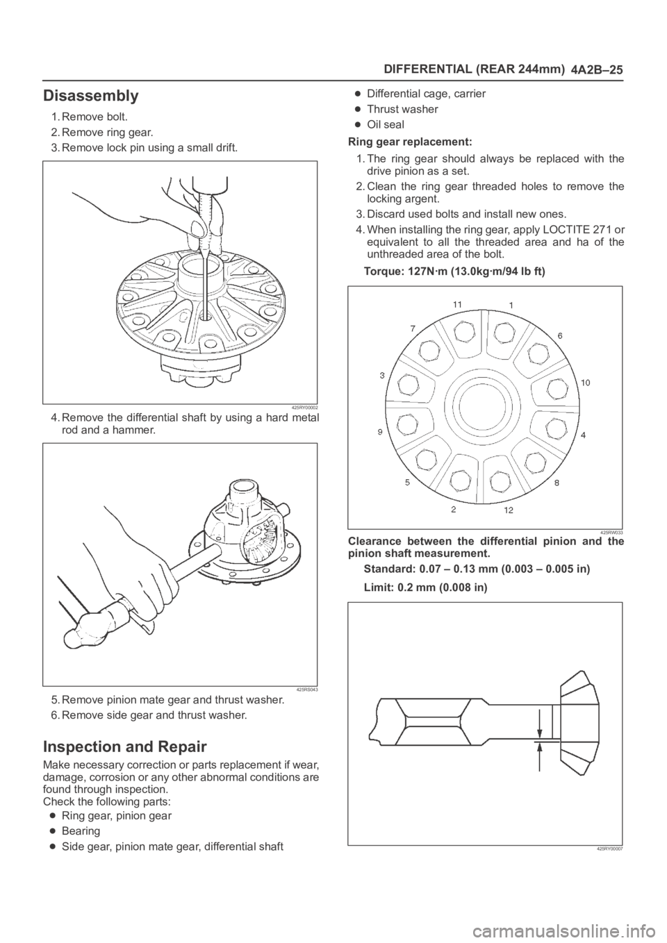
Disassembly
1. Remove bolt.
2. Remove ring gear.
3. Remove lock pin using a small drift.
425RY00002
4. Remove the differential shaft by using a hard metal
rod and a hammer.
425RS043
5. Remove pinion mate gear and thrust washer.
6. Remove side gear and thrust washer.
Inspection and Repair
Make necessary correction or parts replacement if wear,
damage, corrosion or any other abnormal conditions are
found through inspection.
Check the following parts:
Ring gear, pinion gear
Bearing
Side gear, pinion mate gear, differential shaft
Differential cage, carrier
Thrust washer
Oil seal
Ring gear replacement:
1. The ring gear should always be replaced with the
drive pinion as a set.
2. Clean the ring gear threaded holes to remove the
locking argent.
3. Discard used bolts and install new ones.
4. When installing the ring gear, apply LOCTITE 271 or
equivalent to all the threaded area and ha of the
unthreaded area of the bolt.
Torque: 127Nꞏm (13.0kgꞏm/94 lb ft)
425RW033Clearance between the differential pinion and the
pinion shaft measurement.
Standard: 0.07 – 0.13 mm (0.003 – 0.005 in)
Limit: 0.2 mm (0.008 in)
425RY00007
Page 4036 of 6000
DIFFERENTIAL (REAR 244mm)
4A2B–29
Disassembly
Differential Cages A and B
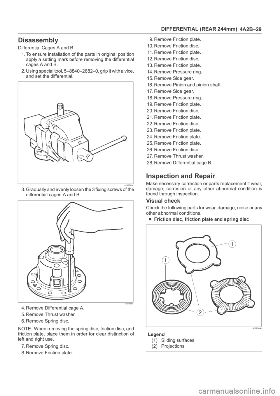
1. To ensure installation of the parts in original position
apply a setting mark before removing the differential
cages A and B.
2. Using special tool, 5–8840–2682–0, grip it with a vice,
and set the differential.
425RS054
3. Gradually and evenly loosen the 3 fixing screws of the
differential cages A and B.
425RS055
4. Remove Differential cage A.
5. Remove Thrust washer.
6. Remove Spring disc.
NOTE: When removing the spring disc, friction disc, and
friction plate, place them in order for clear distinction of
left and right use.
7. Remove Spring disc.
8. Remove Friction plate.9. Remove Friction plate.
10. Remove Friction disc.
11. Remove Friction plate.
12. Remove Friction disc.
13. Remove Friction plate.
14. Remove Pressure ring.
15. Remove Side gear.
16. Remove Pinion and pinion shaft.
17. Remove Side gear.
18. Remove Pressure ring.
19. Remove Friction plate.
20. Remove Friction disc.
21. Remove Friction plate.
22. Remove Friction disc.
23. Remove Friction plate.
24. Remove Friction plate.
25. Remove Friction plate.
26. Remove Friction disc.
27. Remove Thrust washer.
28. Remove Differential cage B.
Inspection and Repair
Make necessary correction or parts replacement if wear,
damage, corrosion or any other abnormal condition is
found through inspection.
Visual check
Check the following parts for wear, damage, noise or any
other abnormal conditions.
Friction disc, friction plate and spring disc
425RS056
Legend
(1) Sliding surfaces
(2) Projections
Page 4070 of 6000
4B1–25 DRIVE LINE CONTROL SYSTEM (SHIFT ON THE FLY)
Diagnosis of the Faults Based on the
Status of 4WD Indicator Lamp, 4WD
Switch and T/F Change Lever
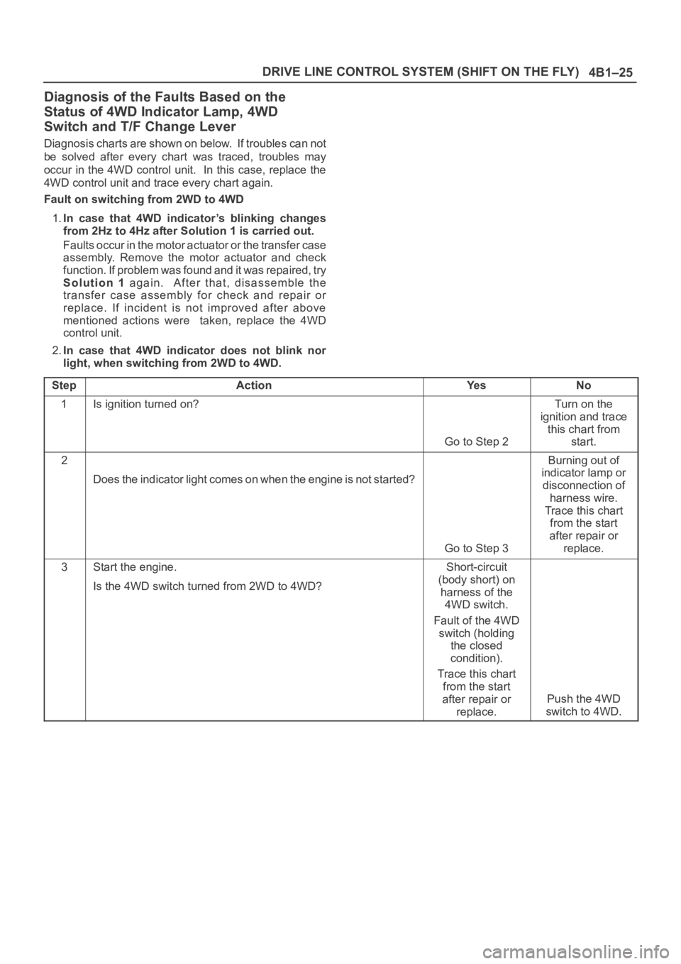
Diagnosis charts are shown on below. If troubles can not
be solved after every chart was traced, troubles may
occur in the 4WD control unit. In this case, replace the
4WD control unit and trace every chart again.
Fault on switching from 2WD to 4WD
1.In case that 4WD indicator’s blinking changes
from 2Hz to 4Hz after Solution 1 is carried out.
Faults occur in the motor actuator or the transfer case
assembly. Remove the motor actuator and check
function. If problem was found and it was repaired, try
Solution 1 again. After that, disassemble the
transfer case assembly for check and repair or
replace. If incident is not improved after above
mentioned actions were taken, replace the 4WD
control unit.
2.In case that 4WD indicator does not blink nor
light, when switching from 2WD to 4WD.
Step
ActionYe sNo
1Is ignition turned on?
Go to Step 2
Turn on the
ignition and trace
this chart from
start.
2
Does the indicator light comes on when the engine is not started?
Go to Step 3
Burning out of
indicator lamp or
disconnection of
harness wire.
Trace this chart
from the start
after repair or
replace.
3Start the engine.
Is the 4WD switch turned from 2WD to 4WD?Short-circuit
(body short) on
harness of the
4WD switch.
Fault of the 4WD
switch (holding
the closed
condition).
Trace this chart
from the start
after repair or
replace.
Push the 4WD
switch to 4WD.
Page 4099 of 6000
DRIVE LINE CONTROL SYSTEM (TOD) 4B2–16
7. Slowly start the vehicle in the 4L mode, and
accelerate to at least 20 km/h. Apply the brake to
completely stop the vehicle.
If the CHECK lamp starts blinking during the test run, read
the trouble codes and give appropriate maintenance
according to the diagnostic procedure. If the TOD
indicator lamps are lit abnormally during the run, check
the lighting condition and give appropriate maintenance
according to the diagnostic procedure. Even if the
phenomena are not observed, try to reproduce the
abnormal state reported by the customer to the possible
extent.
Post-Repair Check
As long as the starter is not turned off, the TOD indicator
lamps continue blinking even after the failed portion
repaired. Therefore, upon completion of repair, be sure to
turn off the starter switch once and then turn on it to
conduct the test run sequence specified in steps 1
through 7 above and check that the TOD indicator lamps
no longer show any faulty status.
Page 4209 of 6000
4C–3 DRIVE SHAFT SYSTEM
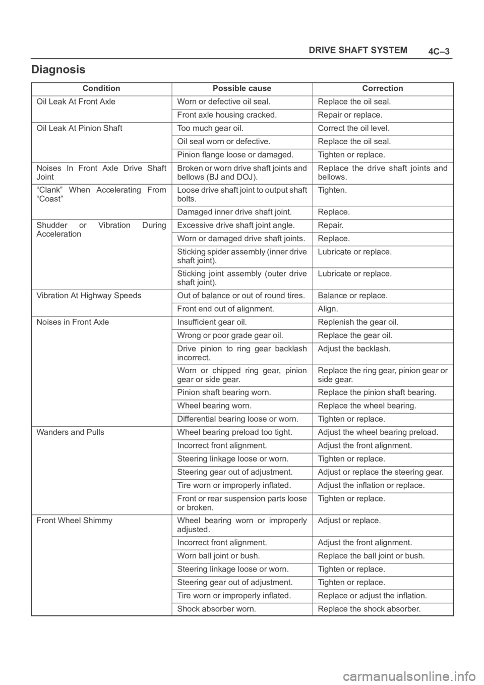
Diagnosis
ConditionPossible causeCorrection
Oil Leak At Front AxleWorn or defective oil seal.Replace the oil seal.
Front axle housing cracked.Repair or replace.
Oil Leak At Pinion ShaftToo much gear oil.Correct the oil level.
Oil seal worn or defective.Replace the oil seal.
Pinion flange loose or damaged.Tighten or replace.
Noises In Front Axle Drive Shaft
JointBroken or worn drive shaft joints and
bellows (BJ and DOJ).Replace the drive shaft joints and
bellows.
“Clank” When Accelerating From
“Coast”Loose drive shaft joint to output shaft
bolts.Tighten.
Damaged inner drive shaft joint.Replace.
Shudder or Vibration During
Acceleration
Excessive drive shaft joint angle.Repair.
AccelerationWorn or damaged drive shaft joints.Replace.
Sticking spider assembly (inner drive
shaft joint).Lubricate or replace.
Sticking joint assembly (outer drive
shaft joint).Lubricate or replace.
Vibration At Highway SpeedsOut of balance or out of round tires.Balance or replace.
Front end out of alignment.Align.
Noises in Front AxleInsufficient gear oil.Replenish the gear oil.
Wrong or poor grade gear oil.Replace the gear oil.
Drive pinion to ring gear backlash
incorrect.Adjust the backlash.
Worn or chipped ring gear, pinion
gear or side gear.Replace the ring gear, pinion gear or
side gear.
Pinion shaft bearing worn.Replace the pinion shaft bearing.
Wheel bearing worn.Replace the wheel bearing.
Differential bearing loose or worn.Tighten or replace.
Wanders and PullsWheel bearing preload too tight.Adjust the wheel bearing preload.
Incorrect front alignment.Adjust the front alignment.
Steering linkage loose or worn.Tighten or replace.
Steering gear out of adjustment.Adjust or replace the steering gear.
Tire worn or improperly inflated.Adjust the inflation or replace.
Front or rear suspension parts loose
or broken.Tighten or replace.
Front Wheel ShimmyWheel bearing worn or improperly
adjusted.Adjust or replace.
Incorrect front alignment.Adjust the front alignment.
Worn ball joint or bush.Replace the ball joint or bush.
Steering linkage loose or worn.Tighten or replace.
Steering gear out of adjustment.Tighten or replace.
Tire worn or improperly inflated.Replace or adjust the inflation.
Shock absorber worn.Replace the shock absorber.
Page 4211 of 6000
4C–5 DRIVE SHAFT SYSTEM
7.Remove the parking brake cable mounting
bolts(Behind the back plate)(1).
311RS001
8. Remove the bearing holder mounting nuts.
9. Remove axle shaft assembly.
NOTE: Be sure not to damage the oil seal.
10. Remove snap ring.
11. Using a bearing remover 5–8840–2295–0 and press,
remove retainer together with the bearing holder.
420RW024
12. Remove bearing.
13. Remove bearing holder.
14. Remove back plate.15. Remove the wheel pins using a remover
5–8840–0079–0.
420RW023
Inspection and Repair
Make necessary correction or parts replacement if wear,
corrosion or any other abnormal conditions are found
through inspection.
Visual Check:
Check the following parts for wear, damage, noise or any
other abnormal conditions:
1. Axle shaft
2. Bearing
When checking the axle shaft, pay special attention to the
splined portions and replace the shaft if distortion or step
wear is noticeable. Correct slight step wear with a grinder.
420RS008