Page 5661 of 6000

6F – 2 ENGINE EXHAUST
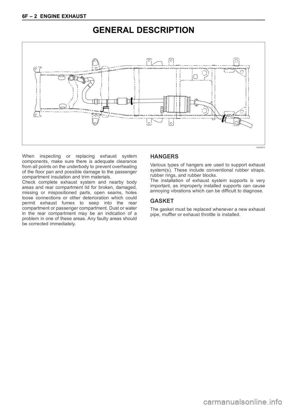
GENERAL DESCRIPTION
150RW070
When inspecting or replacing exhaust system
components, make sure there is adequate clearance
from all points on the underbody to prevent overheating
of the floor pan and possible damage to the passenger
compartment insulation and trim materials.
Check complete exhaust system and nearby body
areas and rear compartment lid for broken, damaged,
missing or mispositioned parts, open seams, holes
loose connections or other deterioration which could
permit exhaust fumes to seep into the rear
compartment or passenger compartment. Dust or water
in the rear compartment may be an indication of a
problem in one of these areas. Any faulty areas should
be corrected immediately.HANGERS
Various types of hangers are used to support exhaust
system(s). These include conventional rubber straps,
rubber rings, and rubber blocks.
The installation of exhaust system supports is very
important, as improperly installed supports can cause
annoying vibrations which can be difficult to diagnose.
GASKET
The gasket must be replaced whenever a new exhaust
pipe, muffler or exhaust throttle is installed.
Page 5662 of 6000
ENGINE EXHAUST 6F – 3
ON-VEHICLE SERVICE
FRONT EXHAUST PIPE
Rattles and noise vibrations in the exhaust system are
usually caused by misalignment of parts. When aligning
the system, leave all bolts or nuts loose until all parts
are properly aligned; then tighten, working from front to
rear.
1. Check connections for looseness or damage,
especially for exhaust gas leakage.
2. Check clamps and rubbers for weakness, cracks or
damage.3. If any part of the converter heat shield is damaged
or dented to the extent that it contacts the catalyst,
repair or replace.
4. Check for dents or damage and for any holes or
cracks caused by corrosion.
3
2 1
Legend
(1) Front exhaust pipe
(2) Center exhaust pipe
(3) Mounting rubber
150RW071
Page 5681 of 6000
6J – 4 INDUCTION
TURBOCHARGER
REMOVAL
2. Drain engine coolant.
3. Remove air cleaner cover and air duct.
4. Remove intercooler assembly.
Refer to “Intercooler” in this manual.
5. Remove water pipe from water inlet of
turbocharger.
6. Remove oil pipe.
1) Remove fixing bolts from oil inlet of turbocharger
then remove oil pipe.
2) Plug open port of turbocharger to prevent
foreign materials from entering the turbocharger.
7. Remove oil drain pipe from turbocharger.
8. Remove water outlet pipe from turbocharger.
9. Remove heat protector.
10. Remove exhaust valve assembly.
11. Remove turbocharger fixing nuts from exhaust
manifold then remove turbocharger assembly.
9875 63
21
4
Legend
(1) Exhaust Manifold
(2) Gasket
(3) Turbocharger Assembly
(4) Water Hose(5) Water Hose
(6) Heat Protector
(7) Oil Pipe
(8) Oil Pipe
(9) Gasket
025RW023
036RW006
Page 5683 of 6000

6J – 6 INDUCTION
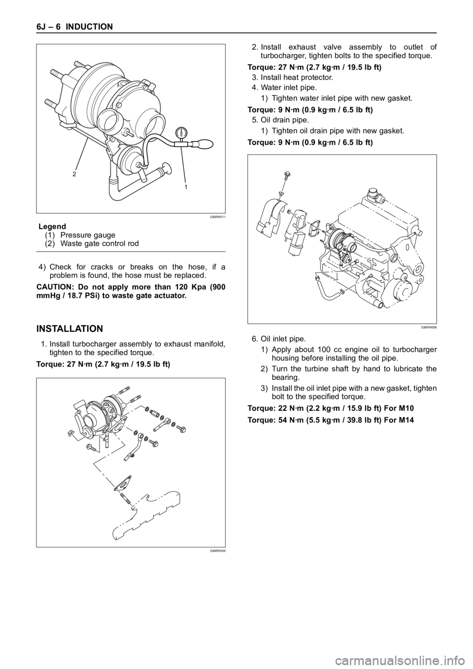
Legend
(1) Pressure gauge
(2) Waste gate control rod
4) Check for cracks or breaks on the hose, if a
problem is found, the hose must be replaced.
CAUTION: Do not apply more than 120 Kpa (900
mmHg / 18.7 PSi) to waste gate actuator.
INSTALLATION
1. Install turbocharger assembly to exhaust manifold,
tighten to the specified torque.
Torque: 27 Nꞏm (2.7 kgꞏm / 19.5 lb ft)2. Install exhaust valve assembly to outlet of
turbocharger, tighten bolts to the specified torque.
Torque: 27 Nꞏm (2.7 kgꞏm / 19.5 lb ft)
3. Install heat protector.
4. Water inlet pipe.
1) Tighten water inlet pipe with new gasket.
Torque: 9 Nꞏm (0.9 kgꞏm / 6.5 lb ft)
5. Oil drain pipe.
1) Tighten oil drain pipe with new gasket.
Torque: 9 Nꞏm (0.9 kgꞏm / 6.5 lb ft)
6. Oil inlet pipe.
1) Apply about 100 cc engine oil to turbocharger
housing before installing the oil pipe.
2) Turn the turbine shaft by hand to lubricate the
bearing.
3) Install the oil inlet pipe with a new gasket, tighten
bolt to the specified torque.
Torque: 22 Nꞏm (2.2 kgꞏm / 15.9 lb ft) For M10
Torque: 54 Nꞏm (5.5 kgꞏm / 39.8 lb ft) For M14
2
1
036RW011
036RW005
036RW006
Page 5684 of 6000
INDUCTION 6J – 7
7. Water inlet pipe.
1) Install water inlet pipe with a new gasket, tighten
bolts to the specified torque.
Torque: 9 Nꞏm (0.9 kgꞏm / 6.5 lb ft)
8. Install intercooler assembly.
Refer to “Intercooler” in this manual.
9. Install air cleaner cover with air duct.
10. Fill engine coolant to full level.
11. Install battery and connect battery cable.
036RW005
Page 5686 of 6000
INDUCTION 6J – 9
REMOVAL
1. Remove intercooler assembly.
Refer to “Intercooler” in this manual.
2. Remove harness connector from motor and ITP
sensor.
3. Loosen the two fixing nuts and remove the throttle
valve assembly.
Legend
(1) Motor
(2) Intake Throttle Valve
(3) ITP sensor
INSPECTION AND REPAIR
1. Check for catching somwhere on the throttle valve.
2. If some problem is discovered during inspection on
the throttle valve, the throttle valve must replace.
INSTALLATION
1. Put gasket on the intake manifold and install throttle
valve.
2. Tighten nuts to the specified torque.
Torque: 20 Nꞏm (2.0 kgꞏm / 14.5 lb ft)
3. Reconnect harness connector to motor and
ITPsensor.
4. Install intercooler assembly.
1 2 3
025RW032
INTAKE THROTTLE VALVE
Page 5687 of 6000
6J – 10 INDUCTION
INTAKE MANIFOLD
REMOVAL
1. Drain engine coolant and remove water hose from
thermostat housing
2. Remove intercooler assembly.
3. Remove bracket fixing bolt of oil level gauge guide
tube.
4. Remove PCV hose.
5. Remove hoses from EGR valve, EGR vacuum
sensor and outlet of heater unit.
6. Disconnect harness connector from MAP sensor,
EGR vacuum sensor, ETC sensor, Water
temperature unit, IAT sensor and EVRV.
7. Remove high pressure oil pipe.
8. Remove two way check valve.
9. Remove fuel pipe.
10. Remove fixing bolts and nuts of intake manifold,
remove intake manifold assembly.
Legend
(1) Intake manifold
(2) Fixing portion of throttle valve
(3) EGR passage
(4) EGR valve
2
3
4
1
Legend
(1) Intake Manifold
(2) Throttle Valve Assembly
(3) EGR Valve
(4) Gasket
025RW022
3124
025RW031
Page 5688 of 6000

INDUCTION 6J – 11
INSPECTION AND RAPAIR
1. Visually check for cracks/clogs inside intake
manifold.
2. If foreign material is observed, it should be taken
out, and if there are some cracks on the intake
manifold, it must be replaced.
INSTALLATION
1. Install the intake manifold assembly, tighten bolts
and to the specified torque.
Torque: 20 Nꞏm (2.0 kgꞏm / 14.5 lb ft) for bolt
Torque: 20 Nꞏm (2.0 kgꞏm / 14.5 lb ft) for nut
2. Install fuel pipe.
Torque: 4 Nꞏm (0.4 kgꞏm / 2.9 lb ft) for M16 nut
(Apply engine oil)
Torque: 13 Nꞏm (1.3 kgꞏm / 9.4 lb ft) for M10 cap nut
Torque: 14 Nꞏm (1.4 kgꞏm / 10 lb ft) for M10
(Apply engine oil)
3. Install two way check valve.
Torque: 20 Nꞏm (2.0 kgꞏm / 14.5 lb ft)
4. Fill with about 300 cc of engine oil from the high
pressure oil pipe installation port of the oil rail using
an oil filler.
If assembled without filling the oil rail with oil, the
time for engine starting will be longer.
5. Install high pressure oil pipe, then tighten sleeve nut
to the specified torque.
Torque: 29 Nꞏm (3.0 kgꞏm / 21.7 lb ft)
6. Reconnect harness connector to MAP sensor, EGR
vacuum sensor, ETC sensor, Water thermo unit,
IAT sensor and EVRV sensor.
7. Install hoses to EGR valve, EGR vacuum sensor
and Water outlet of heater.
8. Connect PCV hose.
9. Install oil level gauge guide and fix it.
10. Install intercooler assembly.
Refer to “Intercooler” in this manual.
11. Install water hose to thermostat housing and fill with
engine coolant.
Model of Turbocharger IHI RHF5
Turbine Maximum Speed 180,000 rpm
Maximum Inlet Gas Temperature 800 °C (1472 °F)
Vibration Peak (G) criteria Maximum 4 (G) at Turbine Rotor Speed 140,000 rpm
Tolerance Limit of Compressor Blade Height Less then 0.5 mm (0.0197 in)
MAIN DATA AND SPECIFICATIONS