Page 5751 of 6000
7A–62
AUTOMATIC TRANSMISSION (4L30–E)
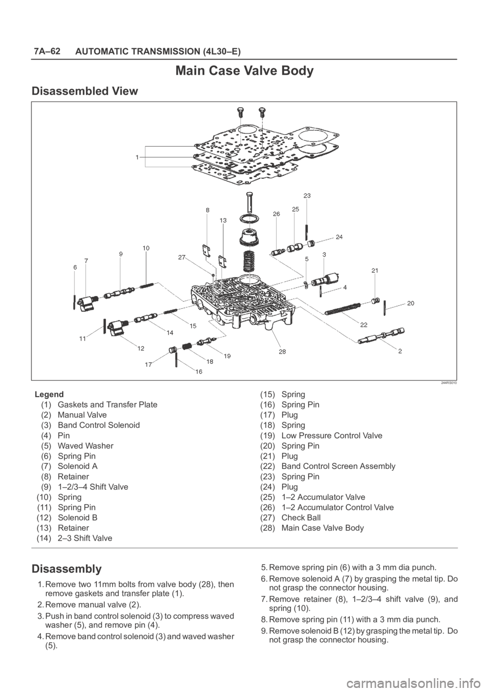
Main Case Valve Body
Disassembled View
244RS010
Legend
(1) Gaskets and Transfer Plate
(2) Manual Valve
(3) Band Control Solenoid
(4) Pin
(5) Waved Washer
(6) Spring Pin
(7) Solenoid A
(8) Retainer
(9) 1–2/3–4 Shift Valve
(10) Spring
(11) Spring Pin
(12) Solenoid B
(13) Retainer
(14) 2–3 Shift Valve(15) Spring
(16) Spring Pin
(17) Plug
(18) Spring
(19) Low Pressure Control Valve
(20) Spring Pin
(21) Plug
(22) Band Control Screen Assembly
(23) Spring Pin
(24) Plug
(25) 1–2 Accumulator Valve
(26) 1–2 Accumulator Control Valve
(27) Check Ball
(28) Main Case Valve Body
Disassembly
1. Remove two 11mm bolts from valve body (28), then
remove gaskets and transfer plate (1).
2. Remove manual valve (2).
3. Push in band control solenoid (3) to compress waved
washer (5), and remove pin (4).
4. Remove band control solenoid (3) and waved washer
(5).5. Remove spring pin (6) with a 3 mm dia punch.
6. Remove solenoid A (7) by grasping the metal tip. Do
not grasp the connector housing.
7. Remove retainer (8), 1–2/3–4 shift valve (9), and
spring (10).
8. Remove spring pin (11) with a 3 mm dia punch.
9. Remove solenoid B (12) by grasping the metal tip. Do
not grasp the connector housing.
Page 5752 of 6000
7A–63 AUTOMATIC TRANSMISSION (4L30–E)
10. Remove retainer (13), 2–3 shift valve (14), and spring
(15).
11. Remove spring pin (16), plug (17), spring (18), and
low pressure control valve (19).
12. Remove spring pin (20), plug (21), and band control
screen assembly (22).
13. Remove spring pin (23), plug (24), 1–2 accumulator
valve (25), and 1–2 accumulator control valve (26).
14. Remove check ball (27) from valve body (28).
Inspection And Repair
Inspect for the following, and replace any damaged or
worn parts:
1. Damage or wear to each valve.
2. Damage in oil passeges.
3. Cracks or damage to valve body.
4. Valve operations.
5. Spring fatigue.
Reassembly
1. Install 1–2 accumulator control valve (26), 1–2
accumulator valve (25), plug (24), and spring pin (23).
2. Install band control screen assembly (22), plug (21),
and spring pin (20).
3. Install low pressure control valve (19), spring (18),
plug (17), and spring pin (16).
4. Install spring (15), 2–3 shift valve (14), retainer (13),
solenoid B (12), and spring pin (11).
5. Install spring (10), 1–2/3–4 shift valve (9), retainer (8),
solenoid A (7), and spring pin (6).
6. Install waved washer (5), band control solenoid (3),
and pin (4).
7. Install manual valve (2).
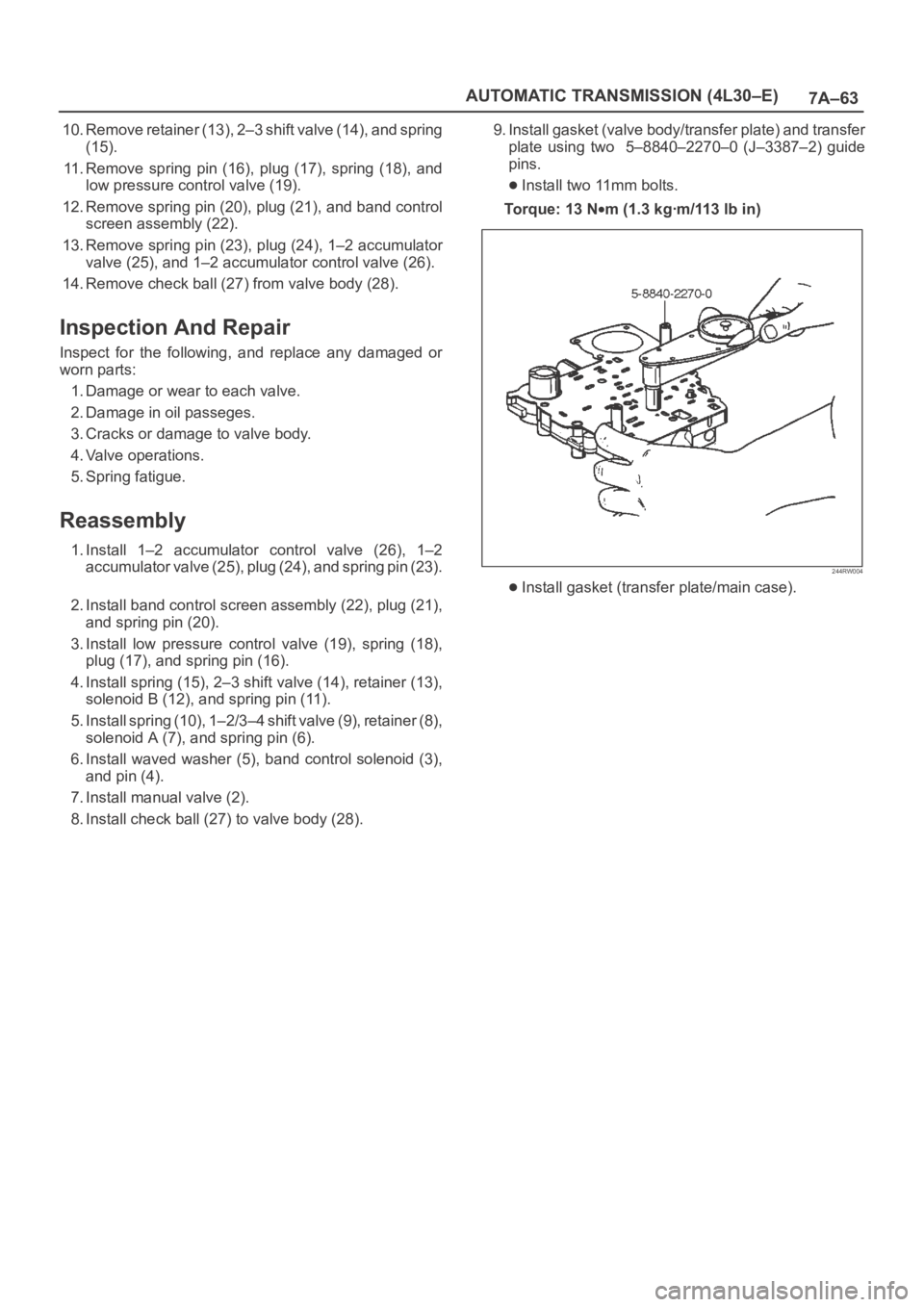
8. Install check ball (27) to valve body (28).9. Install gasket (valve body/transfer plate) and transfer
plate using two 5–8840–2270–0 (J–3387–2) guide
pins.
Install two 11mm bolts.
To r q u e : 1 3 N
m (1.3 kgꞏm/113 lb in)
244RW004
Install gasket (transfer plate/main case).
Page 5763 of 6000
7A–74
AUTOMATIC TRANSMISSION (4L30–E)
Reverse Clutch Piston And Center Support
Disassembled View
242RS006
Legend
(1) Retaining Ring
(2) Spring Seat
(3) Springs
(4) Piston Assembly
(5) Center Support
(6) Gasket(7) Transfer Plate
(8) Gasket
(9) Restrictor
(10) Retainer Plate
(11) Plug
(12) Spring
(13) Overrun Lock Out Valve
Page 5764 of 6000
7A–75 AUTOMATIC TRANSMISSION (4L30–E)
Disassembly
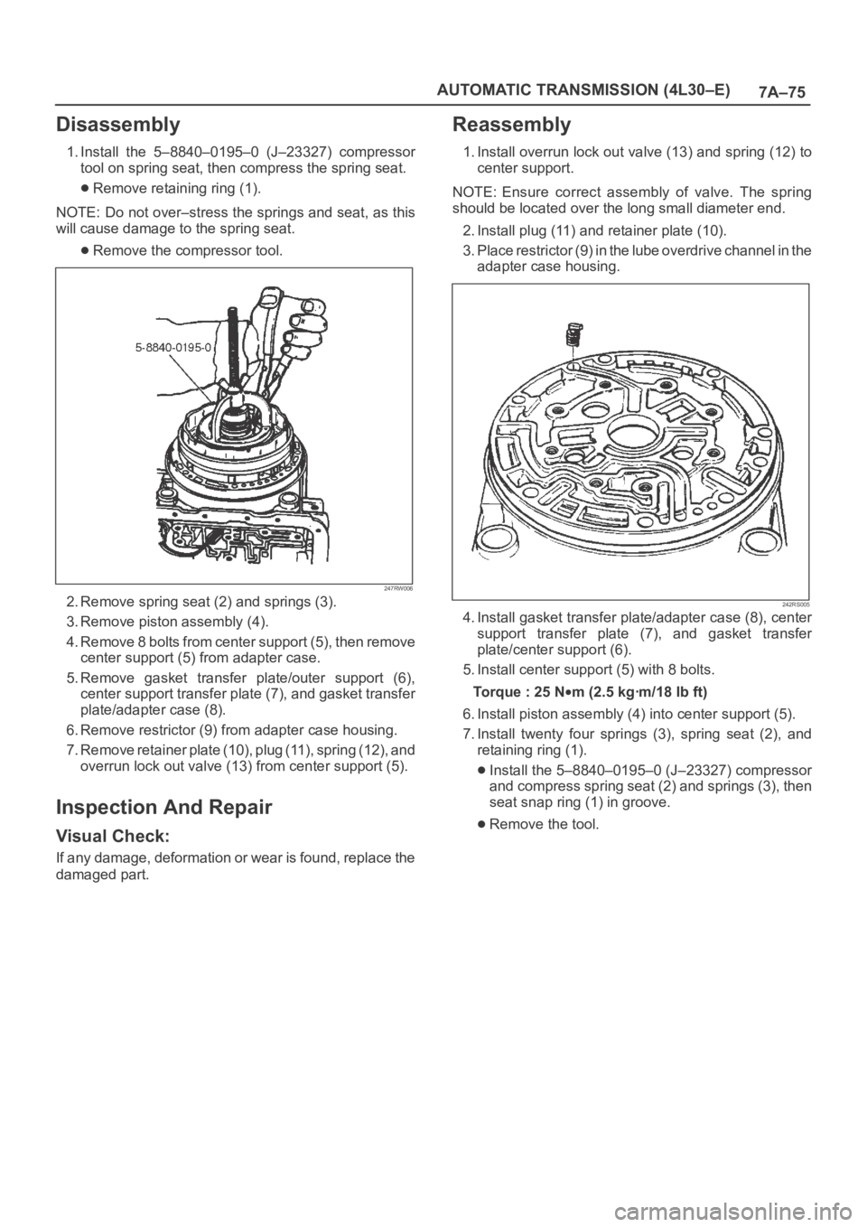
1. Install the 5–8840–0195–0 (J–23327) compressor
tool on spring seat, then compress the spring seat.
Remove retaining ring (1).
NOTE: Do not over–stress the springs and seat, as this
will cause damage to the spring seat.
Remove the compressor tool.
247RW006
2. Remove spring seat (2) and springs (3).
3. Remove piston assembly (4).
4. Remove 8 bolts from center support (5), then remove
center support (5) from adapter case.
5. Remove gasket transfer plate/outer support (6),
center support transfer plate (7), and gasket transfer
plate/adapter case (8).
6. Remove restrictor (9) from adapter case housing.
7. Remove retainer plate (10), plug (11), spring (12), and
overrun lock out valve (13) from center support (5).
Inspection And Repair
Visual Check:
If any damage, deformation or wear is found, replace the
damaged part.
Reassembly
1. Install overrun lock out valve (13) and spring (12) to
center support.
NOTE: Ensure correct assembly of valve. The spring
should be located over the long small diameter end.
2. Install plug (11) and retainer plate (10).
3. Place restrictor (9) in the lube overdrive channel in the
adapter case housing.
242RS005
4. Install gasket transfer plate/adapter case (8), center
support transfer plate (7), and gasket transfer
plate/center support (6).
5. Install center support (5) with 8 bolts.
Torque : 25 N
m (2.5 kgꞏm/18 lb ft)
6. Install piston assembly (4) into center support (5).
7. Install twenty four springs (3), spring seat (2), and
retaining ring (1).
Install the 5–8840–0195–0 (J–23327) compressor
and compress spring seat (2) and springs (3), then
seat snap ring (1) in groove.
Remove the tool.
Page 5773 of 6000
7A–84
AUTOMATIC TRANSMISSION (4L30–E)
ILLUSTRATIONTOOL NO.
TOOL NAME
5–8840–2268–0
(J–38588)
Guide pins; adapter
case to main case
5–8840–2269–0
(J–38555)
Overrun clutch piston
seal installer set
5–8840–2270–0
(J–3387–2)
Guide pins; gasket and
transfer plate to valve
body
5–8840–2271–0
(J–25022)
Turbine shaft puller (Use
with 5–8840–0618–0
(J–24773–1))
5–8840–0196–0
(J–23129)
Oil seal remover (Use
with 5–8840–2266–0
(J–23907) and
5–8840–0019–0
(J–38584))
5–8840–2272–0
(J–38557)
Oil pump centering tool
ILLUSTRATIONTOOL NO.
TOOL NAME
5–8840–2273–0
(J–23082–01)
Oil pump rotation tool
5–8840–0022–0
(J–25025–B)
Guide pins; valve body
to main case
5–8840–2274–0
(J–38428)
Servo piston fitter
5–8840–2275–0
(J–23327–91)
Overrun clutch spring
compressor
5–8840–2277–1
(J–38559–A)
3/4 Accumulator piston
cover compressor
5–8840–2278–0
(J–8763–02)
Holding fixture
Page 5775 of 6000
7A–86
AUTOMATIC TRANSMISSION (4L30–E)
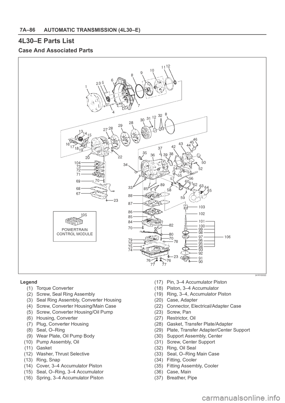
4L30–E Parts List
Case And Associated Parts
241RY00022
Legend
(1) Torque Converter
(2) Screw, Seal Ring Assembly
(3) Seal Ring Assembly, Converter Housing
(4) Screw, Converter Housing/Main Case
(5) Screw, Converter Housing/Oil Pump
(6) Housing, Converter
(7) Plug, Converter Housing
(8) Seal, O–Ring
(9) Wear Plate, Oil Pump Body
(10) Pump Assembly, Oil
(11) Gasket
(12) Washer, Thrust Selective
(13) Ring, Snap
(14) Cover, 3–4 Accumulator Piston
(15) Seal, O–Ring, 3–4 Accumulator
(16) Spring, 3–4 Accumulator Piston(17) Pin, 3–4 Accumulator Piston
(18) Piston, 3–4 Accumulator
(19) Ring, 3–4, Accumulator Piston
(20) Case, Adapter
(22) Connector, Electrical/Adapter Case
(23) Screw, Pan
(27) Restrictor, Oil
(28) Gasket, Transfer Plate/Adapter
(29) Plate, Transfer Adapter/Center Support
(30) Support Assembly, Center
(31) Screw, Center Support
(32) Ring, Oil Seal
(33) Seal, O–Ring Main Case
(34) Fitting, Cooler
(35) Fitting Assembly, Cooler
(36) Case, Main
(37) Breather, Pipe
Page 5776 of 6000
7A–87 AUTOMATIC TRANSMISSION (4L30–E)
(38) Seal, O–Ring
(39) Reservoir
(42) Gasket, Extension Case
(43) Extension Assembly
(44) Seal, O–Ring/Speed Sensor
(45) Sensor Assembly, Speed
(46) Screw, Speed Sensor
(50) Seal, Extension Assembly
(52) Screw, Extension/Main Case
(53) Spring, Parking Pawl Lock
(54) Pawl, Parking Lock
(55) Connector, Electrical/Main Case
(56) Actuator Assembly, Parking Lock
(57) Nut, Parking Lock Lever
(58) Link, Manual Valve
(59) Pin, Spring
(60) Lever, Parking Lock and Range Selector
(61) Shaft, Selector
(62) Seal, Selector Shaft
(63) Mode Switch Assembly
(64) Screw and Conical Washer Assembly
(65) Shield, Mode Switch
(67) Pan, Bottom/Adapter Case
(68) Gasket, Bottom Pan/Adapter Case
(69) Harness Assembly, Adapter Case
(70) Screw, Valve Body
(71) Valve Body Assembly, Adapter Case
(72) Gasket, Adapter Valve Body
(73) Plate, Adapter Valve Body/Transfer
(74) Pan, Bottom/Main Case(75) Gasket, Bottom Pan/Main Case
(76) Gasket, Oil Drain or Overfill Screw
(77) Screw, Oil Drain or Overfill
(78) Magnet, Chip Collector
(79) Filter Oil
(80) Harness Assembly, Main Case
(82) Roller and Spring Assembly, Manual Detent
(84) Valve Body Assembly, Main Case
(85) Ball, Check
(86) Gasket, Main V.B./Transfer Plate
(87) Plate, Main V.B./Transfer
(88) Gasket, Transfer/Main Case
(89) Screw, Transfer Plate on V.B.
(90) Screw, Servo Cover
(91) Cover, Servo Piston
(92) Gasket, Cover/Servo Piston
(93) Ring, Retaining Servo Piston
(94) Clip, Servo Piston
(95) Nut, Servo Screw
(96) Screw, Servo Piston
(97) Piston, Servo
(98) Seal, Ring/Servo Piston
(99) Spring, Cushion/Servo Piston
(100) Seat, Cushion Spring
(101) Sleeve, Servo Piston Adjust
(102) Rod, Apply/Servo Piston
(103) Spring, Return/Servo Piston
(104) Gasket, Adapter Case/Transfer Plate
(105) Powertrain Control Module
(106) Servo Piston Assembly
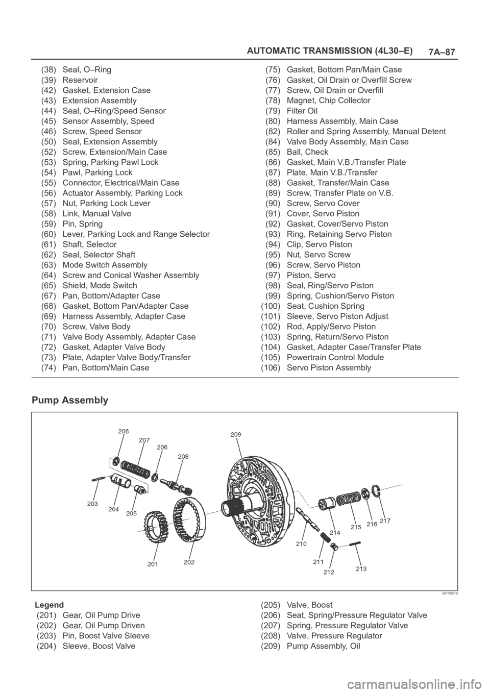
Pump Assembly
241RS019
Legend
(201) Gear, Oil Pump Drive
(202) Gear, Oil Pump Driven
(203) Pin, Boost Valve Sleeve
(204) Sleeve, Boost Valve(205) Valve, Boost
(206) Seat, Spring/Pressure Regulator Valve
(207) Spring, Pressure Regulator Valve
(208) Valve, Pressure Regulator
(209) Pump Assembly, Oil
Page 5856 of 6000

AUTOMATIC TRANSMISSION (AW30-40LE) 7A–75
ON-VEHICLE SERVICE
242RX00001
TRANSIMISSION FLUID LEVEL AND
CONDITION
Park vehicle on level ground and set parking brake.
With the engine idling, move the shift lever through all
positions from "P" to "L", then return to position "P".
Check to see If the level of fluid comes to "HOT" range
of about 80
C (176F) on the dipstick gauge.
If the level of fluid is too low, replenish to bring it to
maximum level in "HOT" range.
Inspection of fluid condition
If the ATF is black or smells burnt, replace it.
ATF REPLACEMENT
NOTE:
Do not overfill.
1) Remove the drain plug from oil pan and drain the
fluid.
2) Reinstall the drain plug securely.
3) With the engine OFF, add new fluid through the filler
tube.
4) Star t the engine and shift the selector into all
position from "P" through "L", and then shift into "P".
5) With the engine idling, check the fluid level. Add fluid
up to the "COLD" level on the dipstick.
6) The ATF level must be checked again for correct
level with the "HOT" level.
NOTE:
To prevent fluid leaks, the drain plug gasket must be
replaced each time this plug is removed.
Tr a n s m i s s i o n
Drain and refill 5.2 L
Dry fill 8.7 L
Fluid BESCO ATF III