1998 OPEL FRONTERA Gas
[x] Cancel search: GasPage 5624 of 6000
6E–195 4JX1–TC ENGINE DRIVEABILITY AND EMISSIONS
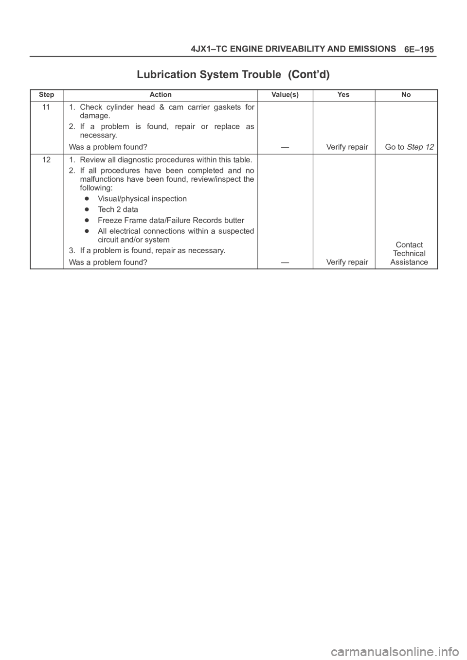
Lubrication System Trouble
StepNo Ye s Va l u e ( s ) Action
111. Check cylinder head & cam carrier gaskets for
damage.
2. If a problem is found, repair or replace as
necessary.
Was a problem found?
—Verify repairGo to Step 12
121. Review all diagnostic procedures within this table.
2. If all procedures have been completed and no
malfunctions have been found, review/inspect the
following:
Visual/physical inspection
Te c h 2 d a t a
Freeze Frame data/Failure Records butter
All electrical connections within a suspected
circuit and/or system
3. If a problem is found, repair as necessary.
Was a problem found?
—Verify repair
Contact
Te c h n i c a l
Assistance
Page 5626 of 6000
6E–197 4JX1–TC ENGINE DRIVEABILITY AND EMISSIONS
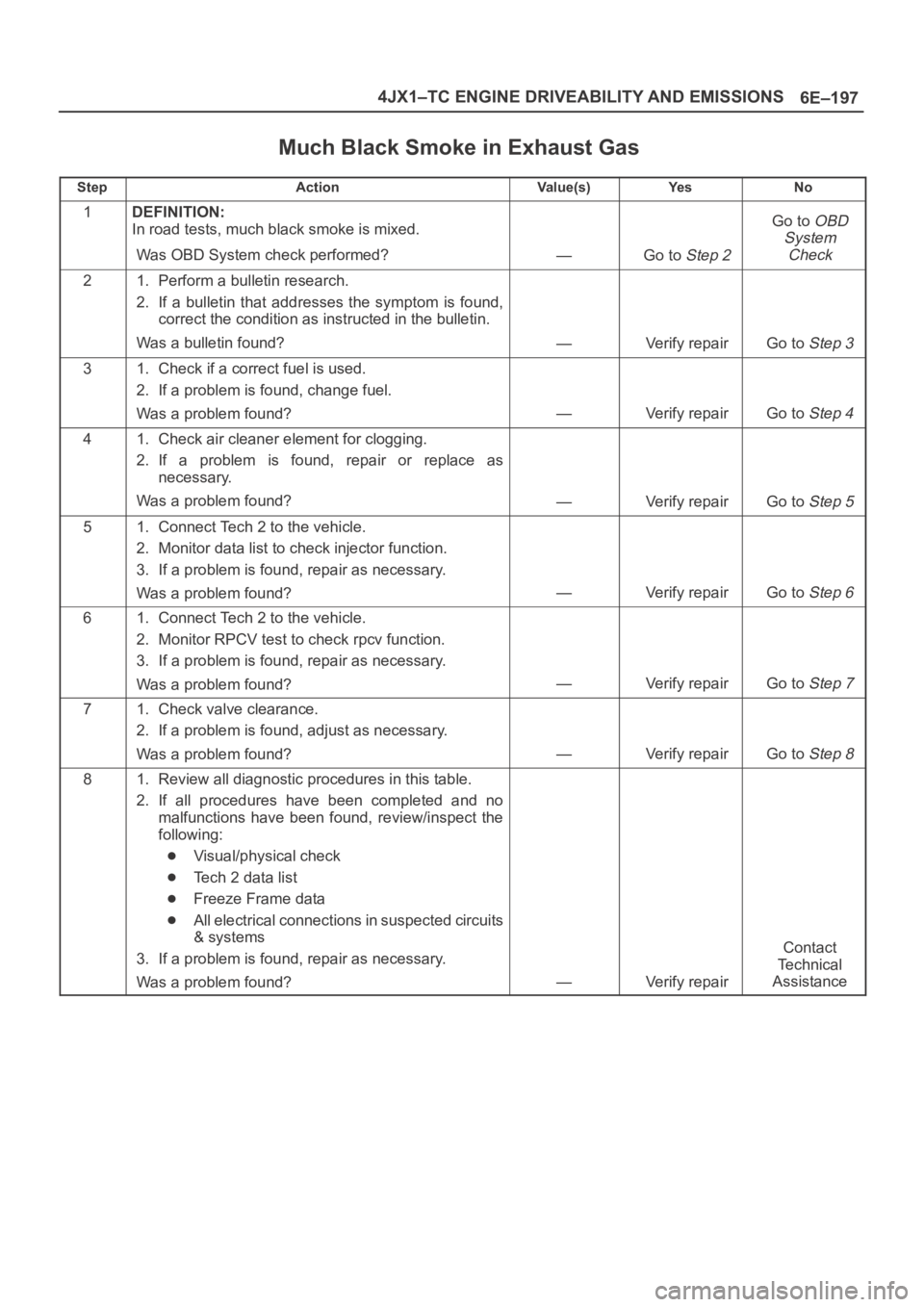
Much Black Smoke in Exhaust Gas
StepActionVa l u e ( s )Ye sNo
1DEFINITION:
In road tests, much black smoke is mixed.
Was OBD System check performed?
—Go to Step 2
Go to OBD
System
Check
21. Perform a bulletin research.
2. If a bulletin that addresses the symptom is found,
correct the condition as instructed in the bulletin.
Was a bulletin found?
—Verify repairGo to Step 3
31. Check if a correct fuel is used.
2. If a problem is found, change fuel.
Was a problem found?
—Verify repairGo to Step 4
41. Check air cleaner element for clogging.
2. If a problem is found, repair or replace as
necessary.
Was a problem found?
—Verify repairGo to Step 5
51. Connect Tech 2 to the vehicle.
2. Monitor data list to check injector function.
3. If a problem is found, repair as necessary.
Was a problem found?
—Verify repairGo to Step 6
61. Connect Tech 2 to the vehicle.
2. Monitor RPCV test to check rpcv function.
3. If a problem is found, repair as necessary.
Was a problem found?
—Verify repairGo to Step 7
71. Check valve clearance.
2. If a problem is found, adjust as necessary.
Was a problem found?
—Verify repairGo to Step 8
81. Review all diagnostic procedures in this table.
2. If all procedures have been completed and no
malfunctions have been found, review/inspect the
following:
Visual/physical check
Tech 2 data list
Freeze Frame data
All electrical connections in suspected circuits
& systems
3. If a problem is found, repair as necessary.
Was a problem found?
—Verify repair
Contact
Te c h n i c a l
Assistance
Page 5627 of 6000
6E–198
4JX1–TC ENGINE DRIVEABILITY AND EMISSIONS
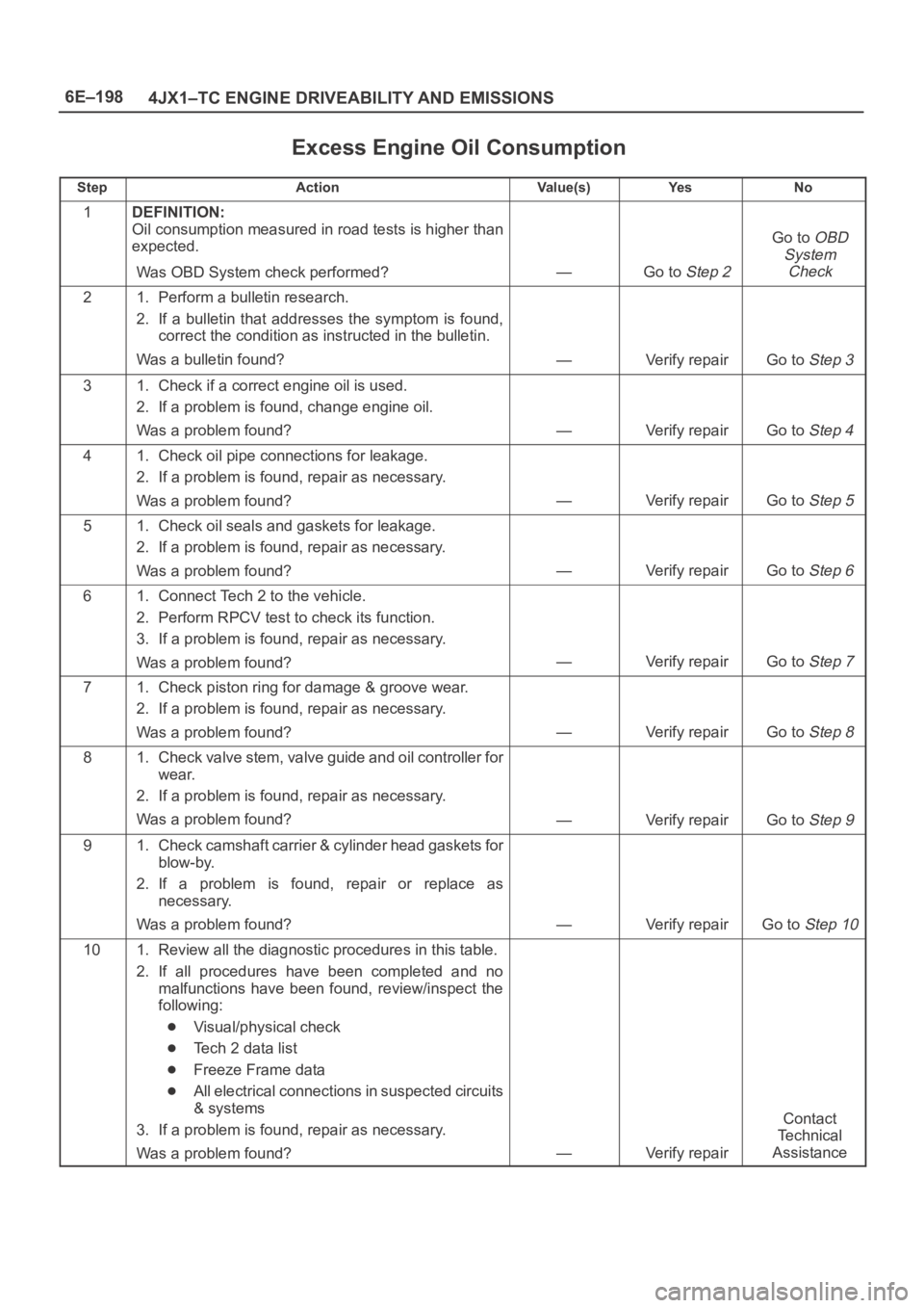
Excess Engine Oil Consumption
StepActionVa l u e ( s )Ye sNo
1DEFINITION:
Oil consumption measured in road tests is higher than
expected.
Was OBD System check performed?
—Go to Step 2
Go to OBD
System
Check
21. Perform a bulletin research.
2. If a bulletin that addresses the symptom is found,
correct the condition as instructed in the bulletin.
Was a bulletin found?
—Verify repairGo to Step 3
31. Check if a correct engine oil is used.
2. If a problem is found, change engine oil.
Was a problem found?
—Verify repairGo to Step 4
41. Check oil pipe connections for leakage.
2. If a problem is found, repair as necessary.
Was a problem found?
—Verify repairGo to Step 5
51. Check oil seals and gaskets for leakage.
2. If a problem is found, repair as necessary.
Was a problem found?
—Verify repairGo to Step 6
61. Connect Tech 2 to the vehicle.
2. Perform RPCV test to check its function.
3. If a problem is found, repair as necessary.
Was a problem found?
—Verify repairGo to Step 7
71. Check piston ring for damage & groove wear.
2. If a problem is found, repair as necessary.
Was a problem found?
—Verify repairGo to Step 8
81. Check valve stem, valve guide and oil controller for
wear.
2. If a problem is found, repair as necessary.
Was a problem found?
—Verify repairGo to Step 9
91. Check camshaft carrier & cylinder head gaskets for
blow-by.
2. If a problem is found, repair or replace as
necessary.
Was a problem found?
—Verify repairGo to Step 10
101. Review all the diagnostic procedures in this table.
2. If all procedures have been completed and no
malfunctions have been found, review/inspect the
following:
Visual/physical check
Tech 2 data list
Freeze Frame data
All electrical connections in suspected circuits
& systems
3. If a problem is found, repair as necessary.
Was a problem found?
—Verify repair
Contact
Te c h n i c a l
Assistance
Page 5643 of 6000
6E–214
4JX1–TC ENGINE DRIVEABILITY AND EMISSIONS
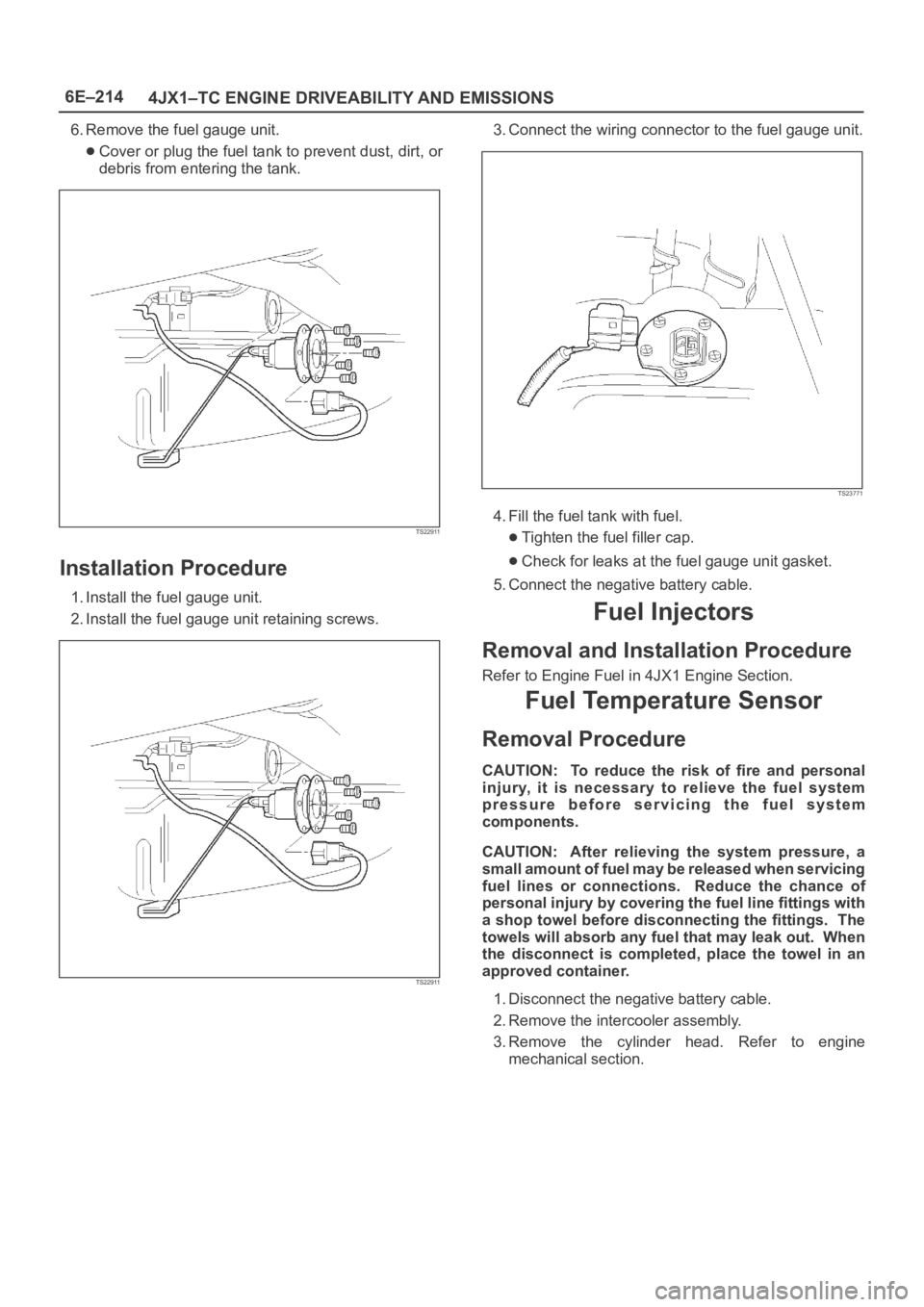
6. Remove the fuel gauge unit.
Cover or plug the fuel tank to prevent dust, dirt, or
debris from entering the tank.
TS22911
Installation Procedure
1. Install the fuel gauge unit.
2. Install the fuel gauge unit retaining screws.
TS22911
3. Connect the wiring connector to the fuel gauge unit.
TS23771
4. Fill the fuel tank with fuel.
Tighten the fuel filler cap.
Check for leaks at the fuel gauge unit gasket.
5. Connect the negative battery cable.
Fuel Injectors
Removal and Installation Procedure
Refer to Engine Fuel in 4JX1 Engine Section.
Fuel Temperature Sensor
Removal Procedure
CAUTION: To reduce the risk of fire and personal
injury, it is necessary to relieve the fuel system
pressure before servicing the fuel system
components.
CAUTION: After relieving the system pressure, a
small amount of fuel may be released when servicing
fuel lines or connections. Reduce the chance of
personal injury by covering the fuel line fittings with
a shop towel before disconnecting the fittings. The
towels will absorb any fuel that may leak out. When
the disconnect is completed, place the towel in an
approved container.
1. Disconnect the negative battery cable.
2. Remove the intercooler assembly.
3. Remove the cylinder head. Refer to engine
mechanical section.
Page 5646 of 6000
6E–217 4JX1–TC ENGINE DRIVEABILITY AND EMISSIONS
Throttle Body (TB)
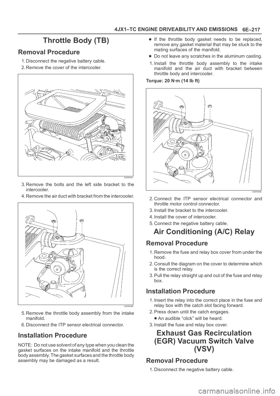
Removal Procedure
1. Disconnect the negative battery cable.
2. Remove the cover of the intercooler.
035RW051
3. Remove the bolts and the left side bracket to the
intercooler.
4 . R e m o v e t h e a i r d u c t w i t h b r a c k e t f r o m t h e i n t e r c o o l e r.
035RW086
5. Remove the throttle body assembly from the intake
manifold.
6. Disconnect the ITP sensor electrical connector.
Installation Procedure
NOTE: Do not use solvent of any type when you clean the
gasket surfaces on the intake manifold and the throttle
body assembly. The gasket surfaces and the throttle body
assembly may be damaged as a result.
If the throttle body gasket needs to be replaced,
remove any gasket material that may be stuck to the
mating surfaces of the manifold.
Do not leave any scratches in the aluminum casting.
1. Install the throttle body assembly to the intake
manifold and the air duct with bracket between
throttle body and intercooler.
Torque: 20 Nꞏm (14 Ib ft)
035RW086
2. Connect the ITP sensor electrical connector and
throttle motor control connector.
3. Install the bracket to the intercooler.
4. Install the cover of intercooler.
5. Connect the negative battery cable.
Air Conditioning (A/C) Relay
Removal Procedure
1. Remove the fuse and relay box cover from under the
hood.
2. Consult the diagram on the cover to determine which
is the correct relay.
3. Pull the relay straight up and out of the fuse and relay
box.
Installation Procedure
1. Insert the relay into the correct place in the fuse and
relay box with the catch slot facing forward.
2. Press down until the catch engages.
An audible “click” will be heard.
3. Install the fuse and relay box cover.
Exhaust Gas Recirculation
(EGR) Vacuum Switch Valve
(VSV)
Removal Procedure
1. Disconnect the negative battery cable.
Page 5655 of 6000
6E–226
4JX1–TC ENGINE DRIVEABILITY AND EMISSIONS
0018
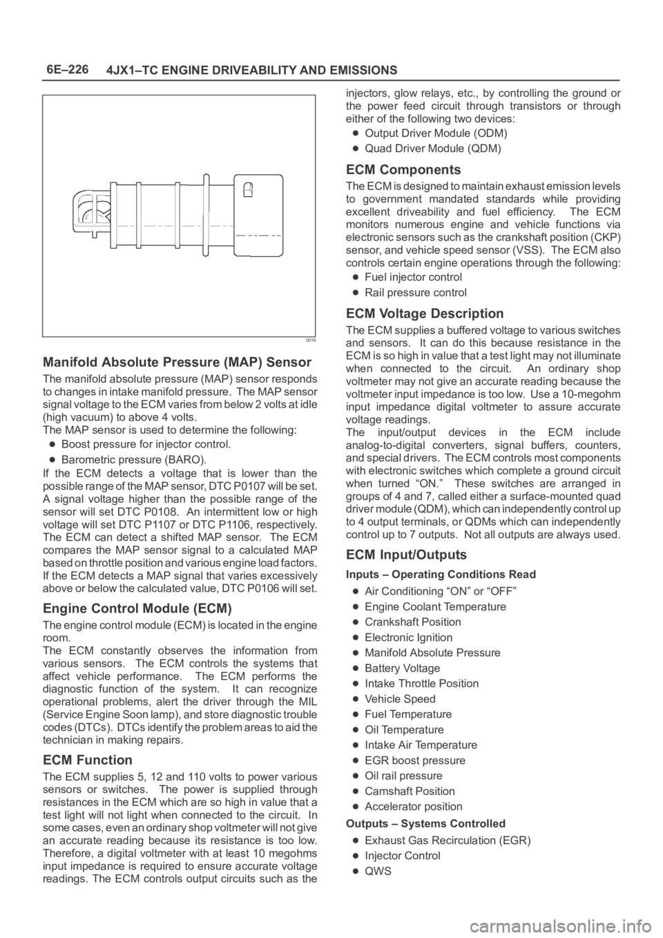
Manifold Absolute Pressure (MAP) Sensor
The manifold absolute pressure (MAP) sensor responds
to changes in intake manifold pressure. The MAP sensor
signal voltage to the ECM varies from below 2 volts at idle
(high vacuum) to above 4 volts.
The MAP sensor is used to determine the following:
Boost pressure for injector control.
Barometric pressure (BARO).
If the ECM detects a voltage that is lower than the
possible range of the MAP sensor, DTC P0107 will be set.
A signal voltage higher than the possible range of the
sensor will set DTC P0108. An intermittent low or high
voltage will set DTC P1107 or DTC P1106, respectively.
The ECM can detect a shifted MAP sensor. The ECM
compares the MAP sensor signal to a calculated MAP
based on throttle position and various engine load factors.
If the ECM detects a MAP signal that varies excessively
above or below the calculated value, DTC P0106 will set.
Engine Control Module (ECM)
The engine control module (ECM) is located in the engine
room.
The ECM constantly observes the information from
various sensors. The ECM controls the systems that
affect vehicle performance. The ECM performs the
diagnostic function of the system. It can recognize
operational problems, alert the driver through the MIL
(Service Engine Soon lamp), and store diagnostic trouble
codes (DTCs). DTCs identify the problem areas to aid the
technician in making repairs.
ECM Function
The ECM supplies 5, 12 and 110 volts to power various
sensors or switches. The power is supplied through
resistances in the ECM which are so high in value that a
test light will not light when connected to the circuit. In
some cases, even an ordinary shop voltmeter will not give
an accurate reading because its resistance is too low.
Therefore, a digital voltmeter with at least 10 megohms
input impedance is required to ensure accurate voltage
readings. The ECM controls output circuits such as theinjectors, glow relays, etc., by controlling the ground or
the power feed circuit through transistors or through
either of the following two devices:
Output Driver Module (ODM)
Quad Driver Module (QDM)
ECM Components
The ECM is designed to maintain exhaust emission levels
to government mandated standards while providing
excellent driveability and fuel efficiency. The ECM
monitors numerous engine and vehicle functions via
electronic sensors such as the crankshaft position (CKP)
sensor, and vehicle speed sensor (VSS). The ECM also
controls certain engine operations through the following:
Fuel injector control
Rail pressure control
ECM Voltage Description
The ECM supplies a buffered voltage to various switches
and sensors. It can do this because resistance in the
ECM is so high in value that a test light may not illuminate
when connected to the circuit. An ordinary shop
voltmeter may not give an accurate reading because the
voltmeter input impedance is too low. Use a 10-megohm
input impedance digital voltmeter to assure accurate
voltage readings.
The input/output devices in the ECM include
analog-to-digital converters, signal buffers, counters,
and special drivers. The ECM controls most components
with electronic switches which complete a ground circuit
when turned “ON.” These switches are arranged in
groups of 4 and 7, called either a surface-mounted quad
driver module (QDM), which can independently control up
to 4 output terminals, or QDMs which can independently
control up to 7 outputs. Not all outputs are always used.
ECM Input/Outputs
Inputs – Operating Conditions Read
Air Conditioning “ON” or “OFF”
Engine Coolant Temperature
Crankshaft Position
Electronic Ignition
Manifold Absolute Pressure
Battery Voltage
Intake Throttle Position
Vehicle Speed
Fuel Temperature
Oil Temperature
Intake Air Temperature
EGR boost pressure
Oil rail pressure
Camshaft Position
Accelerator position
Outputs – Systems Controlled
Exhaust Gas Recirculation (EGR)
Injector Control
QWS
Page 5657 of 6000
6E–228
4JX1–TC ENGINE DRIVEABILITY AND EMISSIONS
General Description (Air Induction)
Air Induction System
The air induction system filters contaminants from the
outside air, and directs the progress of the air as it is
drawn into the engine. A remote-mounted air cleaner
prevents dirt and debris in the air from entering the
engine. The air duct assembly routes filtered air to the
throttle body. Air enters the engine by to following steps:
1. Through the throttle body.
2. Into the intake manifold.
3. Through the cylinder head intake ports.
4. Into the cylinders.
General Description (Fuel Metering)
Deceleration Mode
The ECM reduces the amount of fuel injected when it
detects a decrease in the Accelerator position.
Fuel Injector
Fuel injector comprises the solenoid, hydraulic line, and
fuel line. Fuel injection is controlled by the continuity time
signal and continuity start timing signal from ECM to the
solenoid
ECM determines the running conditions of engine by
input signals such as engine speed. Accelerator throttle
valve opening, and engine coolant temperature, thereby
to send the solenoid the best suited signal to the engine
status. When current is carried to the solenoid, the
armature opens the poppet valve to alow high pressure oil
to run into the injector. Under the pressure of the oil, the
piston and plunger are depressed to compress the fuel in
the combustion chamber of the plunger. Specifically, the
pressure of the fuel compressed is increased by a piston
top/ plunger bottom area ratio over the pressure of high
pressure oil, thereby lifting the fuel nozzle end needle for
injecting fuel.
Fuel Metering System Components
The fuel metering system is made up of the following
parts:
The fuel injectors.
The intake throttle body.
The Accelerator position (AP) sensor
The ECM.
The crankshaft position (CKP) sensor.
The camshaft position (CMP) sensor.
Basic System Operation
Fuel is supplied through fuel filter to the fuel pump.
The fuel pump is installed to the oil pump, and fuel is
forced, through the fuel pump outlet, pipe and cylinder
head inside, into the fuel injector.
An orifice is provided at the rear fuel outlet of cylinder
head to control the pressure of oil.The injector is controlled by ECM which gives
opening/closing commands to the solenoid installed on
the top of the injector. Opening/closing operation of the
pressurized engine oil circuit of the injector controls fuel
injection quantity, fuel injection timing, etc.
A/C Clutch Diagnosis
A/C Request Signal
This signal tells the ECM when the A/C mode is selected
at the A/C control head. The ECM uses this to adjust the
idle speed.
Refer to
A/C Clutch Circuit Diagnosis for A/C wiring
diagrams and diagnosis for A/C electrical system.
General Description Exhaust Gas
Recirculation (EGR) System
EGR Purpose
The exhaust gas recirculation (EGR) system is use to
reduce emission levels of oxides of nitrogen (NOx). NOx
emission levels are caused by a high combustion
temperature. The EGR system lowers the NOx emission
levels by decreasing the combustion temperature.
The ECM uses information from the following sensors to
control EGR valve boost pressure.
ECT
ITP
Engine Speed
AP sensor
Page 5660 of 6000
ENGINE EXHAUST 6F – 1
ENGINE EXHAUST
CONTENTS
CAUTION: Exhaust system components must have
enough clearance from the underbody to prevent
overheating of the floor pan and possible damage to the passenger compartment, insulation and trim
materials.
General Description . . . . . . . . . . . . . . . . . . 6F–2
Hangers . . . . . . . . . . . . . . . . . . . . . . . . . 6F–2
Gasket . . . . . . . . . . . . . . . . . . . . . . . . . . 6F–2
On-Vehicle Service . . . . . . . . . . . . . . . . . . . 6F–3
Front Exhaust Pipe . . . . . . . . . . . . . . . . . 6F–3Center Exhaust Pipe . . . . . . . . . . . . . . . . 6F–5
Exhaust Silencer . . . . . . . . . . . . . . . . . . . 6F–6
Rear Exhaust Pipe . . . . . . . . . . . . . . . . . 6F–7