1998 OPEL FRONTERA gas type
[x] Cancel search: gas typePage 4094 of 6000
4B2–11 DRIVE LINE CONTROL SYSTEM (TOD)
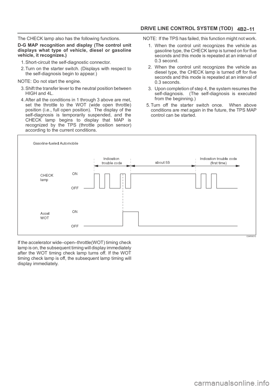
The CHECK lamp also has the following functions.
D-G MAP recognition and display (The control unit
displays what type of vehicle, diesel or gasoline
vehicle, it recognizes.)
1. Short-circuit the self-diagnostic connector.
2. Turn on the starter switch. (Displays with respect to
the self-diagnosis begin to appear.)
NOTE: Do not start the engine.
3. Shift the transfer lever to the neutral position between
HIGH and 4L.
4. After all the conditions in 1 through 3 above are met,
set the throttle to the WOT (wide open throttle)
position (i.e., full open position). The display of the
self-diagnosis is temporarily suspended, and the
CHECK lamp begins to display that MAP is
recognized by the TPS (throttle position sensor)
according to the current conditions.NOTE: If the TPS has failed, this function might not work.
1. When the control unit recognizes the vehicle as
gasoline type, the CHECK lamp is turned on for five
seconds and this mode is repeated at an interval of
0.3 second.
2. When the control unit recognizes the vehicle as
diesel type, the CHECK lamp is turned off for five
seconds and this mode is repeated at an interval of
0.3 seconds.
3. Upon completion of step 4, the system resumes the
self-diagnosis. (The self-diagnosis is executed
from the beginning.)
5. Turn off the starter switch once. When above
conditions are met again in the future, the TPS MAP
control can be started.
C04RW010
If the accelerator wide–open–throttle(WOT) timing check
lamp is on, the subsequent timing will display immediately
after the WOT timing check lamp turns off. If the WOT
timing check lamp is off, the subsequent lamp timing will
display immediately.
Page 4274 of 6000
TRANSFER CASE (STANDARD TYPE)
4D1–13
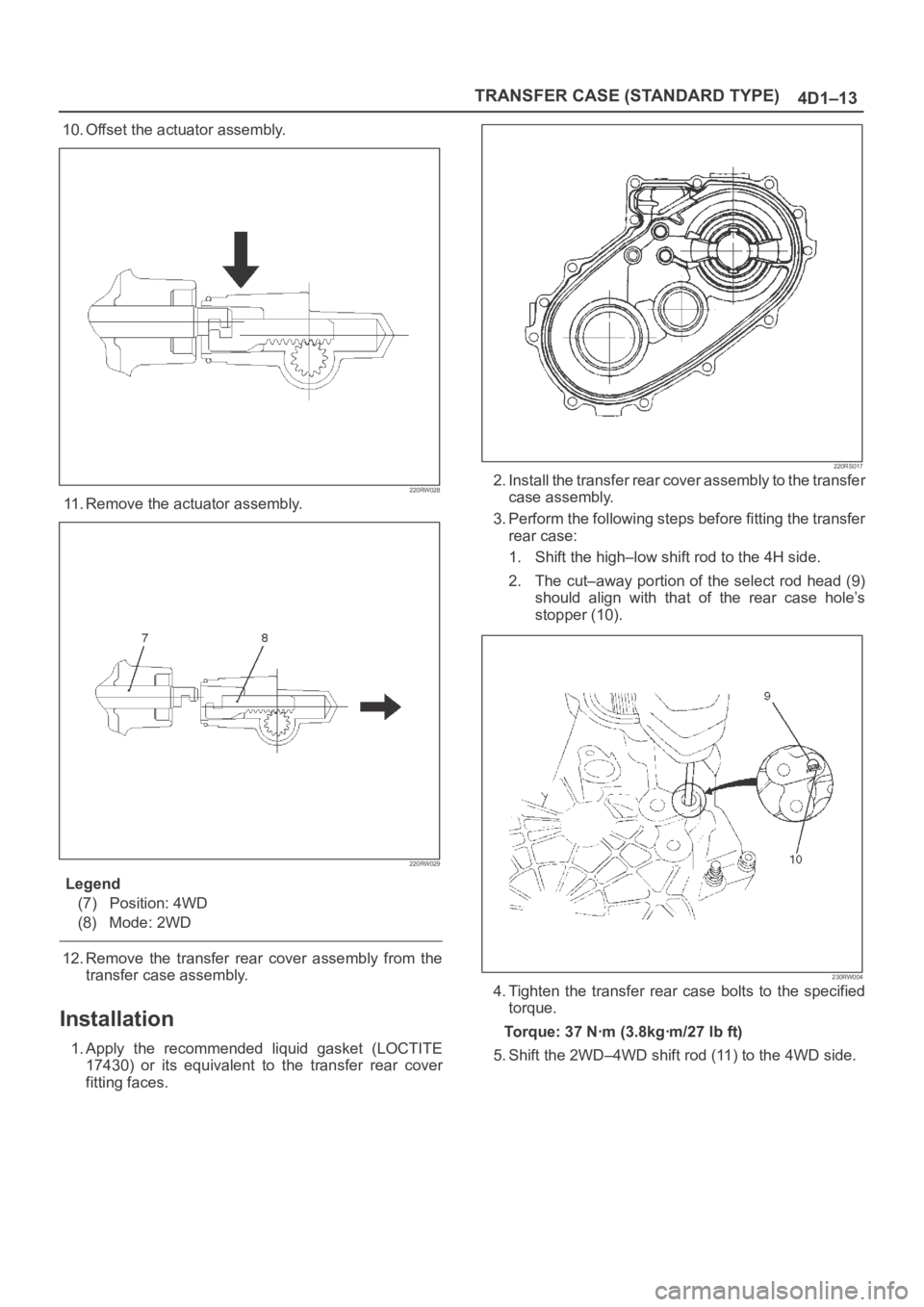
10. Offset the actuator assembly.
220RW028
11. Remove the actuator assembly.
220RW029
Legend
(7) Position: 4WD
(8) Mode: 2WD
12. Remove the transfer rear cover assembly from the
transfer case assembly.
Installation
1. Apply the recommended liquid gasket (LOCTITE
17430) or its equivalent to the transfer rear cover
fitting faces.
220RS017
2. Install the transfer rear cover assembly to the transfer
case assembly.
3. Perform the following steps before fitting the transfer
rear case:
1. Shift the high–low shift rod to the 4H side.
2. The cut–away portion of the select rod head (9)
should align with that of the rear case hole’s
stopper (10).
230RW004
4. Tighten the transfer rear case bolts to the specified
torque.
Torque: 37 Nꞏm (3.8kgꞏm/27 lb ft)
5. Shift the 2WD–4WD shift rod (11) to the 4WD side.
Page 4281 of 6000
4D1–20
TRANSFER CASE (STANDARD TYPE)
Removal
1. Remove the speedometer sensor.
2. Remove the plate.
3. Remove the speedometer driven gear bushing and
driven gear.
NOTE: Apply a reference mark to the driven gear bushing
before removal.
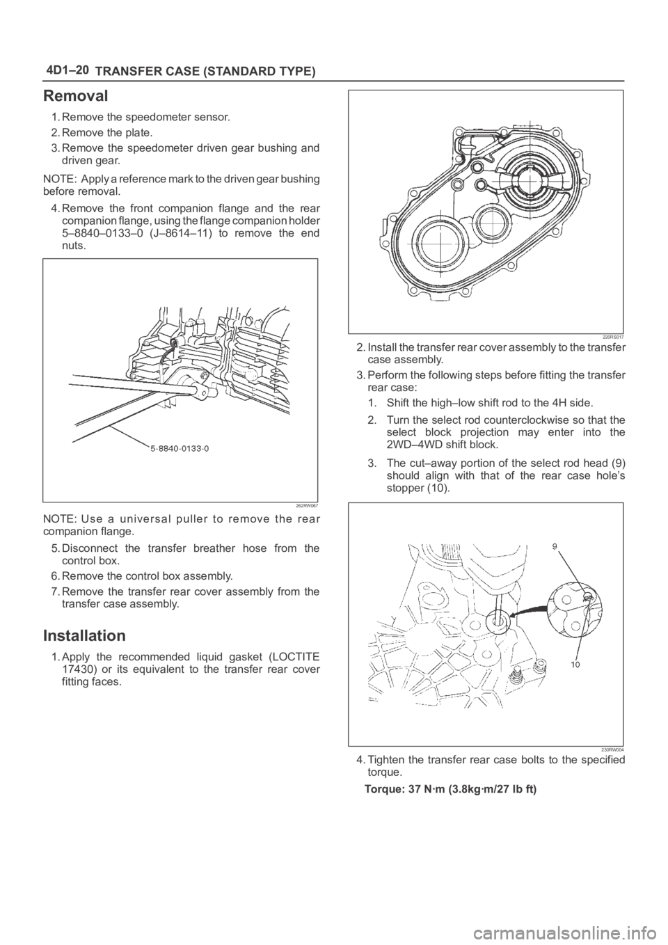
4. Remove the front companion flange and the rear
companion flange, using the flange companion holder
5–8840–0133–0 (J–8614–11) to remove the end
nuts.
262RW067
NOTE: Use a universal puller to remove the rear
companion flange.
5. Disconnect the transfer breather hose from the
control box.
6. Remove the control box assembly.
7. Remove the transfer rear cover assembly from the
transfer case assembly.
Installation
1. Apply the recommended liquid gasket (LOCTITE
17430) or its equivalent to the transfer rear cover
fitting faces.
220RS017
2. Install the transfer rear cover assembly to the transfer
case assembly.
3. Perform the following steps before fitting the transfer
rear case:
1. Shift the high–low shift rod to the 4H side.
2. Turn the select rod counterclockwise so that the
select block projection may enter into the
2WD–4WD shift block.
3. The cut–away portion of the select rod head (9)
should align with that of the rear case hole’s
stopper (10).
230RW004
4. Tighten the transfer rear case bolts to the specified
torque.
Torque: 37 Nꞏm (3.8kgꞏm/27 lb ft)
Page 4289 of 6000
4D1–28
TRANSFER CASE (STANDARD TYPE)
Inspection and Repair
Refer to “TRANSFER CASE ASSEMBLY” in this section
for inspection and repair.
Reassembly
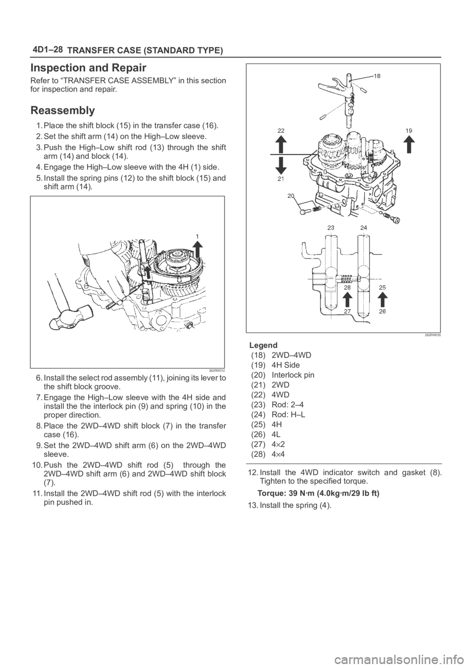
1. Place the shift block (15) in the transfer case (16).
2. Set the shift arm (14) on the High–Low sleeve.
3. Push the High–Low shift rod (13) through the shift
arm (14) and block (14).
4. Engage the High–Low sleeve with the 4H (1) side.
5. Install the spring pins (12) to the shift block (15) and
shift arm (14).
262RW012
6 . I n s t a l l t h e s e l e c t r o d a s s e m b l y ( 11 ) , j o i n i n g i t s l e v e r t o
the shift block groove.
7. Engage the High–Low sleeve with the 4H side and
install the the interlock pin (9) and spring (10) in the
proper direction.
8. Place the 2WD–4WD shift block (7) in the transfer
case (16).
9. Set the 2WD–4WD shift arm (6) on the 2WD–4WD
sleeve.
10. Push the 2WD–4WD shift rod (5) through the
2WD–4WD shift arm (6) and 2WD–4WD shift block
(7).
11. Install the 2WD–4WD shift rod (5) with the interlock
pin pushed in.
262RW035
Legend
(18) 2WD–4WD
(19) 4H Side
(20) Interlock pin
(21) 2WD
(22) 4WD
(23) Rod: 2–4
(24) Rod: H–L
(25) 4H
(26) 4L
(27) 4
2
(28) 4
4
12. Install the 4WD indicator switch and gasket (8).
Tighten to the specified torque.
Torque: 39 Nꞏm (4.0kgꞏm/29 lb ft)
13. Install the spring (4).
Page 4621 of 6000
6D1–2
ENGINE ELECTRICAL
Battery
General Description
There are six battery fluid caps on top of the battery.
These are covered by a paper label.
The battery is completely sealed except for the six small
vent holes on the side. These vent holes permit the
escape of small amounts of gas generated by the battery.
This type of battery has the following advantages over
conventional batteries:
1. There is no need to add water during the entire
service life of the battery.
2. The battery protects itself against overcharging.
The battery will refuse to accept an extensive charge.
(A conventional battery will accept an excessive
charge, resulting in gassing and loss of battery fluid.)
3. The battery is much less vulnerable to self discharge
than a conventional type battery.
Diagnosis
1. Visual Inspection
Inspect the battery for obvious physical damage, such as
a cracked or broken case, which would permit electrolyte
loss.
Replace the battery if obvious physical damage is
discovered during inspection.
Check for any other physical damage and correct it as
necessary.
2. Hydrometer Check
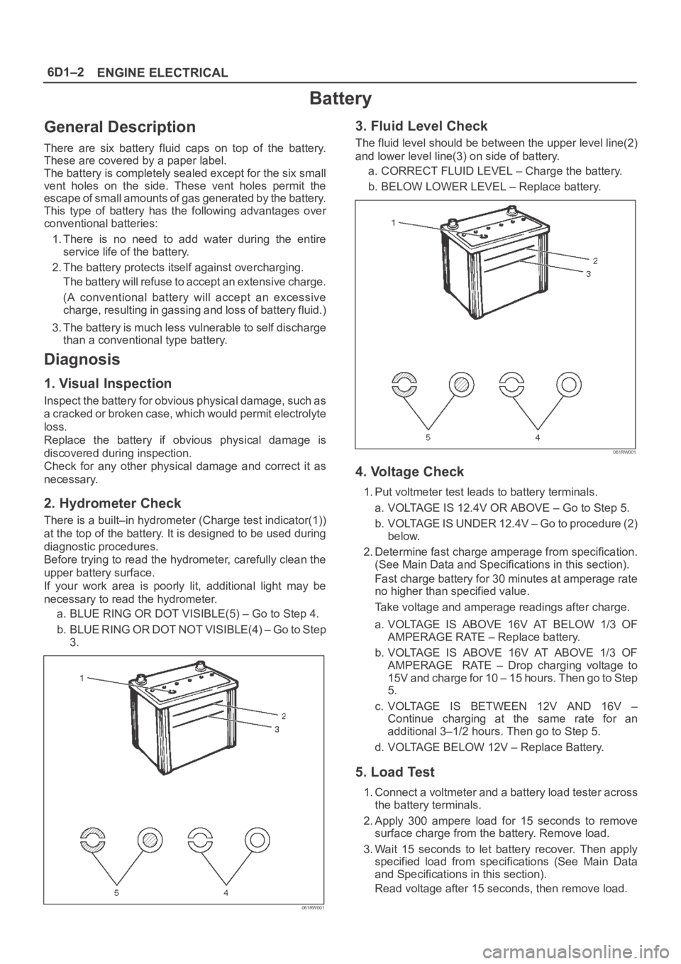
There is a built–in hydrometer (Charge test indicator(1))
at the top of the battery. It is designed to be used during
diagnostic procedures.
Before trying to read the hydrometer, carefully clean the
upper battery surface.
If your work area is poorly lit, additional light may be
necessary to read the hydrometer.
a. BLUE RING OR DOT VISIBLE(5) – Go to Step 4.
b . B L U E R I N G O R D O T N O T V I S I B L E ( 4 ) – G o t o S t e p
3.
061RW001
3. Fluid Level Check
The fluid level should be between the upper level line(2)
and lower level line(3) on side of battery.
a. CORRECT FLUID LEVEL – Charge the battery.
b. BELOW LOWER LEVEL – Replace battery.
061RW001
4. Voltage Check
1. Put voltmeter test leads to battery terminals.
a. VOLTAGE IS 12.4V OR ABOVE – Go to Step 5.
b. VOLTAGE IS UNDER 12.4V – Go to procedure (2)
below.
2. Determine fast charge amperage from specification.
(See Main Data and Specifications in this section).
Fast charge battery for 30 minutes at amperage rate
no higher than specified value.
Take voltage and amperage readings after charge.
a. VOLTAGE IS ABOVE 16V AT BELOW 1/3 OF
AMPERAGE RATE – Replace battery.
b. VOLTAGE IS ABOVE 16V AT ABOVE 1/3 OF
AMPERAGE RATE – Drop charging voltage to
15V and charge for 10 – 15 hours. Then go to Step
5.
c. VOLTAGE IS BETWEEN 12V AND 16V –
Continue charging at the same rate for an
additional 3–1/2 hours. Then go to Step 5.
d. VOLTAGE BELOW 12V – Replace Battery.
5. Load Test
1. Connect a voltmeter and a battery load tester across
the battery terminals.
2. Apply 300 ampere load for 15 seconds to remove
surface charge from the battery. Remove load.
3. Wait 15 seconds to let battery recover. Then apply
specified load from specifications (See Main Data
and Specifications in this section).
Read voltage after 15 seconds, then remove load.
Page 4629 of 6000
6D2–4
IGNITION SYSTEM
Spark Plug
Removal
1. Remove spark plugs.
Inspection and Repair
The spark plug affects entire engine performance and
therefore its inspection is very important.
Check electrode and insulator for presence of cracks,
and replace if any.
Check electrode for wear, and replace if necessary.
Check gasket for damage, and replace if necessary.
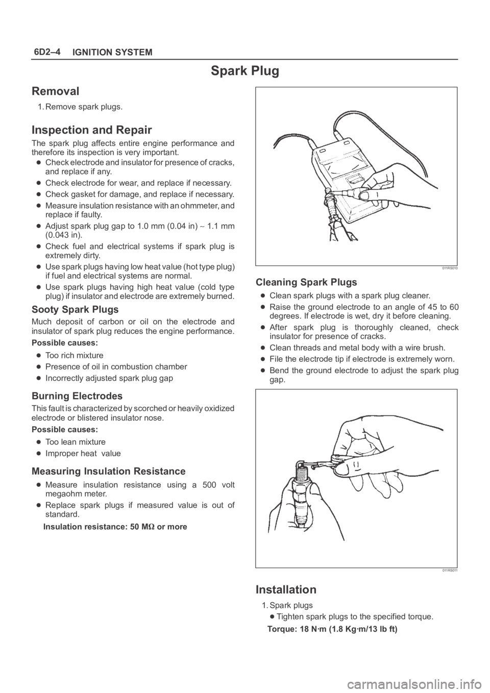
Measure insulation resistance with an ohmmeter, and
replace if faulty.
Adjust spark plug gap to 1.0 mm (0.04 in) 1.1 mm
(0.043 in).
Check fuel and electrical systems if spark plug is
extremely dirty.
Use spark plugs having low heat value (hot type plug)
if fuel and electrical systems are normal.
Use spark plugs having high heat value (cold type
plug) if insulator and electrode are extremely burned.
Sooty Spark Plugs
Much deposit of carbon or oil on the electrode and
insulator of spark plug reduces the engine performance.
Possible causes:
Too rich mixture
Presence of oil in combustion chamber
Incorrectly adjusted spark plug gap
Burning Electrodes
This fault is characterized by scorched or heavily oxidized
electrode or blistered insulator nose.
Possible causes:
Too lean mixture
Improper heat value
Measuring Insulation Resistance
Measure insulation resistance using a 500 volt
megaohm meter.
Replace spark plugs if measured value is out of
standard.
Insulation resistance: 50 M
or more
011RS010
Cleaning Spark Plugs
Clean spark plugs with a spark plug cleaner.
Raise the ground electrode to an angle of 45 to 60
degrees. If electrode is wet, dry it before cleaning.
After spark plug is thoroughly cleaned, check
insulator for presence of cracks.
Clean threads and metal body with a wire brush.
File the electrode tip if electrode is extremely worn.
Bend the ground electrode to adjust the spark plug
gap.
011RS011
Installation
1. Spark plugs
Tighten spark plugs to the specified torque.
Torque: 18 Nꞏm (1.8 Kgꞏm/13 lb ft)
Page 4971 of 6000
6E–314
ENGINE DRIVEABILITY AND EMISSIONS
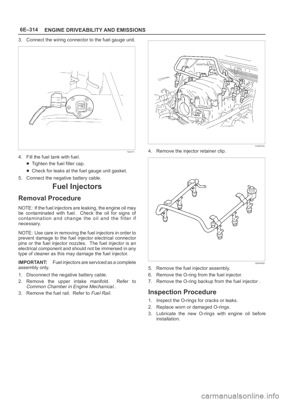
3. Connect the wiring connector to the fuel gauge unit.
TS23771
4. Fill the fuel tank with fuel.
Tighten the fuel filler cap.
Check for leaks at the fuel gauge unit gasket.
5. Connect the negative battery cable.
Fuel Injectors
Removal Procedure
NOTE: If the fuel injectors are leaking, the engine oil may
be contaminated with fuel. Check the oil for signs of
contamination and change the oil and the filter if
necessary.
NOTE: Use care in removing the fuel injectors in order to
prevent damage to the fuel injector electrical connector
pins or the fuel injector nozzles. The fuel injector is an
electrical component and should not be immersed in any
type of cleaner as this may damage the fuel injector.
IMPORTANT:Fuel injectors are serviced as a complete
assembly only.
1. Disconnect the negative battery cable.
2. Remove the upper intake manifold. Refer to
Common Chamber in Engine Mechanical..
3. Remove the fuel rail. Refer to
Fuel Rail.
014RW164
4. Remove the injector retainer clip.
055RW009
5. Remove the fuel injector assembly.
6. Remove the O-ring from the fuel injector.
7. Remove the O-ring backup from the fuel injector .
Inspection Procedure
1. Inspect the O-rings for cracks or leaks.
2. Replace worn or damaged O-rings.
3. Lubricate the new O-rings with engine oil before
installation.
Page 4980 of 6000
6E–323 ENGINE DRIVEABILITY AND EMISSIONS
11. Connect the fuel filler fuse at the tank.
12. Connect the air breather hose at the tank.
TS23796
13. Fill the fuel tank with fuel.
14. Tighten the fuel filler cap.
15. Connect the negative battery cable.
Throttle Body (TB)
Removal Procedure
1. Disconnect the negative battery cable.
2. Drain the cooling system. Refer to
Cooling System.
3. Remove the accelerator cable assembly. Refer to
Accelerator Cable in Engine Speed Control System..
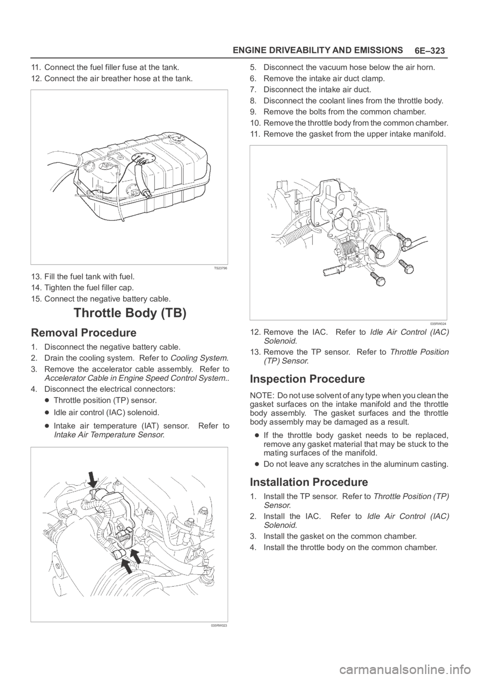
4. Disconnect the electrical connectors:
Throttle position (TP) sensor.
Idle air control (IAC) solenoid.
Intake air temperature (IAT) sensor. Refer to
Intake Air Temperature Sensor.
035RW023
5. Disconnect the vacuum hose below the air horn.
6. Remove the intake air duct clamp.
7. Disconnect the intake air duct.
8. Disconnect the coolant lines from the throttle body.
9. Remove the bolts from the common chamber.
10. Remove the throttle body from the common chamber.
11. Remove the gasket from the upper intake manifold.
035RW024
12. Remove the IAC. Refer to Idle Air Control (IAC)
Solenoid
.
13. Remove the TP sensor. Refer to
Throttle Position
(TP) Sensor
.
Inspection Procedure
NOTE: Do not use solvent of any type when you clean the
gasket surfaces on the intake manifold and the throttle
body assembly. The gasket surfaces and the throttle
body assembly may be damaged as a result.
If the throttle body gasket needs to be replaced,
remove any gasket material that may be stuck to the
mating surfaces of the manifold.
Do not leave any scratches in the aluminum casting.
Installation Procedure
1. Install the TP sensor. Refer to Throttle Position (TP)
Sensor
.
2. Install the IAC. Refer to
Idle Air Control (IAC)
Solenoid
.
3. Install the gasket on the common chamber.
4. Install the throttle body on the common chamber.