Page 1089 of 6000
6D2–4
IGNITION SYSTEM
Spark Plug
Removal
1. Remove spark plugs.
Inspection and Repair
The spark plug affects entire engine performance and
therefore its inspection is very important.
Check electrode and insulator for presence of cracks,
and replace if any.
Check electrode for wear, and replace if necessary.
Check gasket for damage, and replace if necessary.
Measure insulation resistance with an ohmmeter, and
replace if faulty.
Adjust spark plug gap to 1.0 mm (0.04 in) 1.1 mm
(0.043 in).
Check fuel and electrical systems if spark plug is
extremely dirty.
Use spark plugs having low heat value (hot type plug)
if fuel and electrical systems are normal.
Use spark plugs having high heat value (cold type
plug) if insulator and electrode are extremely burned.
Sooty Spark Plugs
Much deposit of carbon or oil on the electrode and
insulator of spark plug reduces the engine performance.
Possible causes:
Too rich mixture
Presence of oil in combustion chamber
Incorrectly adjusted spark plug gap
Burning Electrodes
This fault is characterized by scorched or heavily oxidized
electrode or blistered insulator nose.
Possible causes:
Too lean mixture
Improper heat value
Measuring Insulation Resistance
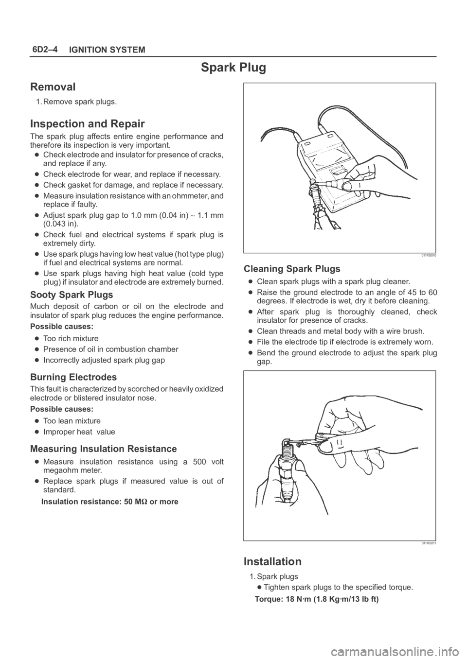
Measure insulation resistance using a 500 volt
megaohm meter.
Replace spark plugs if measured value is out of
standard.
Insulation resistance: 50 M
or more
011RS010
Cleaning Spark Plugs
Clean spark plugs with a spark plug cleaner.
Raise the ground electrode to an angle of 45 to 60
degrees. If electrode is wet, dry it before cleaning.
After spark plug is thoroughly cleaned, check
insulator for presence of cracks.
Clean threads and metal body with a wire brush.
File the electrode tip if electrode is extremely worn.
Bend the ground electrode to adjust the spark plug
gap.
011RS011
Installation
1. Spark plugs
Tighten spark plugs to the specified torque.
Torque: 18 Nꞏm (1.8 Kgꞏm/13 lb ft)
Page 1431 of 6000
6E–314
ENGINE DRIVEABILITY AND EMISSIONS
3. Connect the wiring connector to the fuel gauge unit.
TS23771
4. Fill the fuel tank with fuel.
Tighten the fuel filler cap.
Check for leaks at the fuel gauge unit gasket.
5. Connect the negative battery cable.
Fuel Injectors
Removal Procedure
NOTE: If the fuel injectors are leaking, the engine oil may
be contaminated with fuel. Check the oil for signs of
contamination and change the oil and the filter if
necessary.
NOTE: Use care in removing the fuel injectors in order to
prevent damage to the fuel injector electrical connector
pins or the fuel injector nozzles. The fuel injector is an
electrical component and should not be immersed in any
type of cleaner as this may damage the fuel injector.
IMPORTANT:Fuel injectors are serviced as a complete
assembly only.
1. Disconnect the negative battery cable.
2. Remove the upper intake manifold. Refer to
Common Chamber in Engine Mechanical..
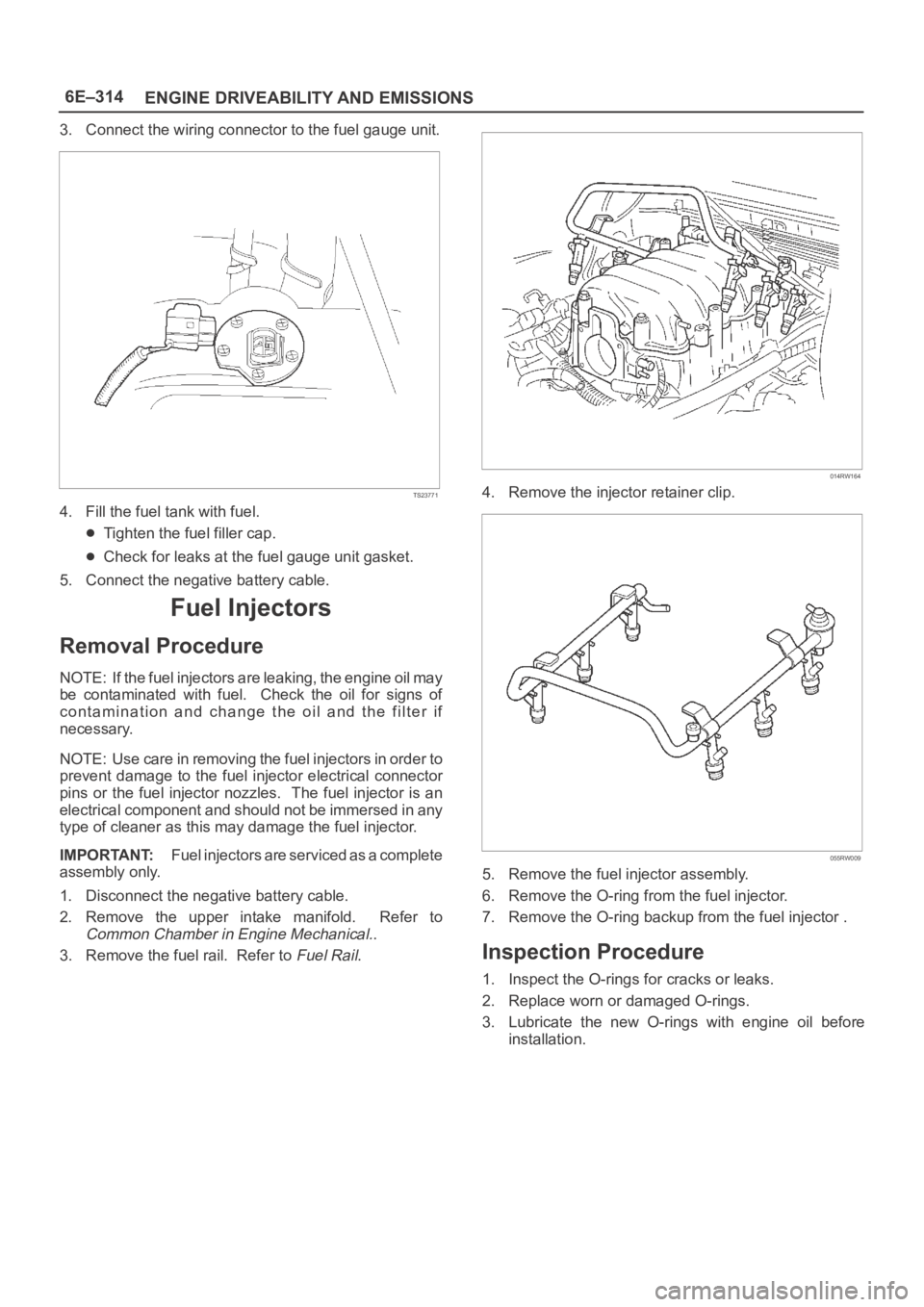
3. Remove the fuel rail. Refer to
Fuel Rail.
014RW164
4. Remove the injector retainer clip.
055RW009
5. Remove the fuel injector assembly.
6. Remove the O-ring from the fuel injector.
7. Remove the O-ring backup from the fuel injector .
Inspection Procedure
1. Inspect the O-rings for cracks or leaks.
2. Replace worn or damaged O-rings.
3. Lubricate the new O-rings with engine oil before
installation.
Page 1440 of 6000
6E–323 ENGINE DRIVEABILITY AND EMISSIONS
11. Connect the fuel filler fuse at the tank.
12. Connect the air breather hose at the tank.
TS23796
13. Fill the fuel tank with fuel.
14. Tighten the fuel filler cap.
15. Connect the negative battery cable.
Throttle Body (TB)
Removal Procedure
1. Disconnect the negative battery cable.
2. Drain the cooling system. Refer to
Cooling System.
3. Remove the accelerator cable assembly. Refer to
Accelerator Cable in Engine Speed Control System..
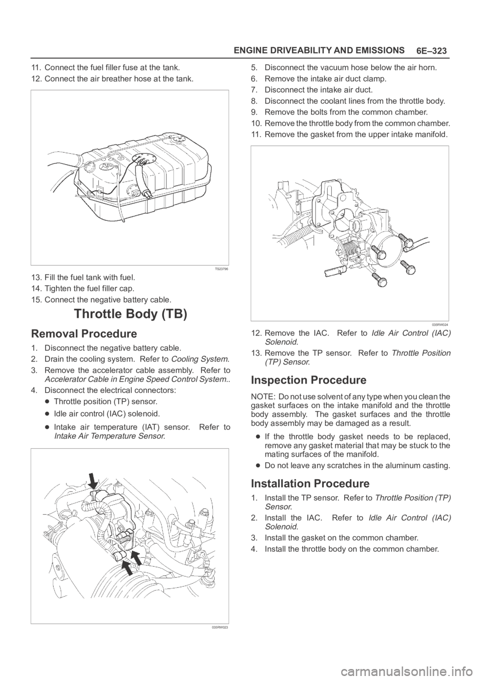
4. Disconnect the electrical connectors:
Throttle position (TP) sensor.
Idle air control (IAC) solenoid.
Intake air temperature (IAT) sensor. Refer to
Intake Air Temperature Sensor.
035RW023
5. Disconnect the vacuum hose below the air horn.
6. Remove the intake air duct clamp.
7. Disconnect the intake air duct.
8. Disconnect the coolant lines from the throttle body.
9. Remove the bolts from the common chamber.
10. Remove the throttle body from the common chamber.
11. Remove the gasket from the upper intake manifold.
035RW024
12. Remove the IAC. Refer to Idle Air Control (IAC)
Solenoid
.
13. Remove the TP sensor. Refer to
Throttle Position
(TP) Sensor
.
Inspection Procedure
NOTE: Do not use solvent of any type when you clean the
gasket surfaces on the intake manifold and the throttle
body assembly. The gasket surfaces and the throttle
body assembly may be damaged as a result.
If the throttle body gasket needs to be replaced,
remove any gasket material that may be stuck to the
mating surfaces of the manifold.
Do not leave any scratches in the aluminum casting.
Installation Procedure
1. Install the TP sensor. Refer to Throttle Position (TP)
Sensor
.
2. Install the IAC. Refer to
Idle Air Control (IAC)
Solenoid
.
3. Install the gasket on the common chamber.
4. Install the throttle body on the common chamber.
Page 1474 of 6000
6F–3 ENGINE EXHAUST
For Isuzu General Motors (IGM)
150RW058
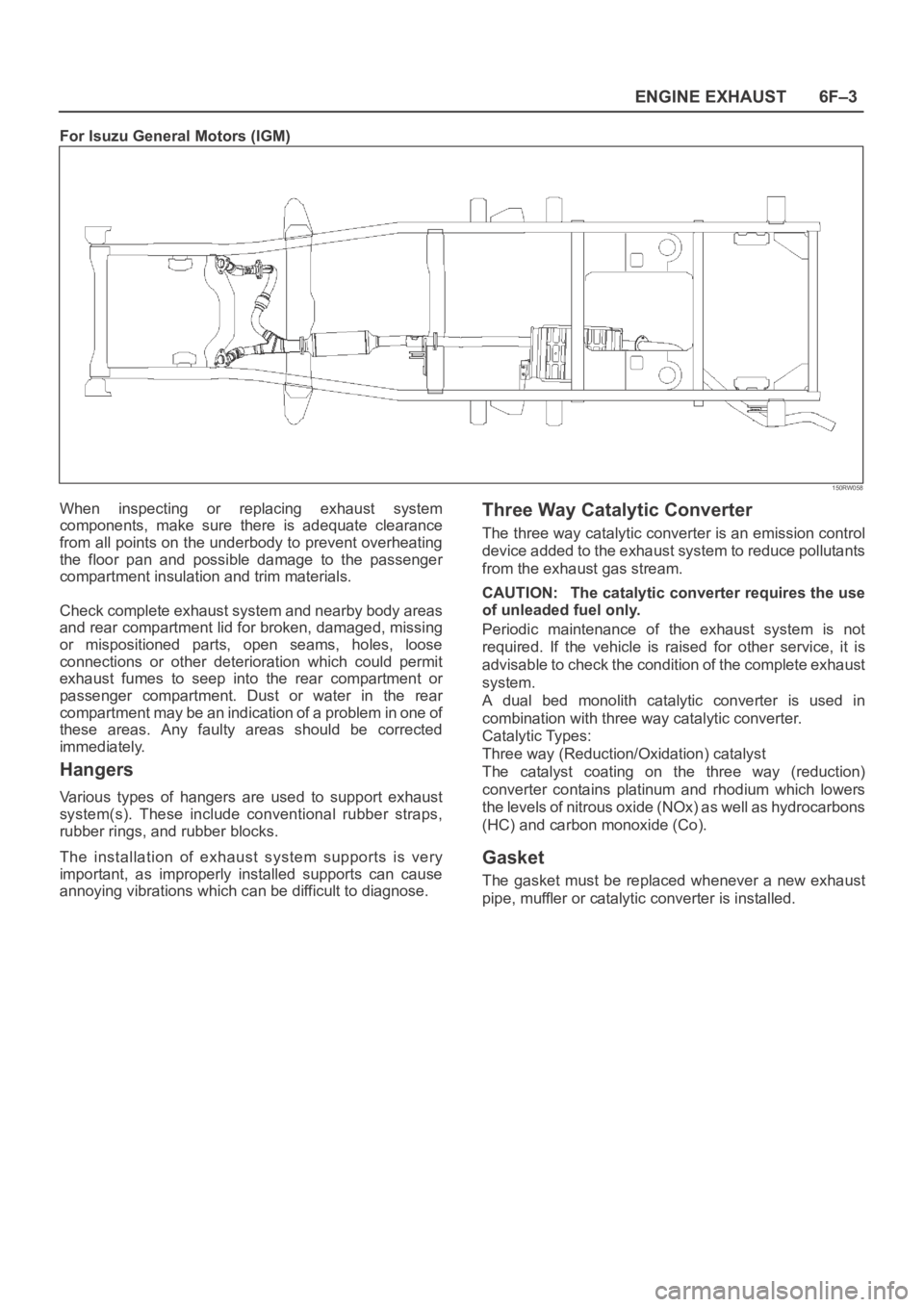
When inspecting or replacing exhaust system
components, make sure there is adequate clearance
from all points on the underbody to prevent overheating
the floor pan and possible damage to the passenger
compartment insulation and trim materials.
Check complete exhaust system and nearby body areas
and rear compartment lid for broken, damaged, missing
or mispositioned parts, open seams, holes, loose
connections or other deterioration which could permit
exhaust fumes to seep into the rear compartment or
passenger compartment. Dust or water in the rear
compartment may be an indication of a problem in one of
these areas. Any faulty areas should be corrected
immediately.
Hangers
Various types of hangers are used to support exhaust
system(s). These include conventional rubber straps,
rubber rings, and rubber blocks.
The installation of exhaust system supports is very
important, as improperly installed supports can cause
annoying vibrations which can be difficult to diagnose.
Three Way Catalytic Converter
The three way catalytic converter is an emission control
device added to the exhaust system to reduce pollutants
from the exhaust gas stream.
CAUTION: The catalytic converter requires the use
of unleaded fuel only.
Periodic maintenance of the exhaust system is not
required. If the vehicle is raised for other service, it is
advisable to check the condition of the complete exhaust
system.
A dual bed monolith catalytic converter is used in
combination with three way catalytic converter.
Catalytic Types:
Three way (Reduction/Oxidation) catalyst
The catalyst coating on the three way (reduction)
converter contains platinum and rhodium which lowers
the levels of nitrous oxide (NOx) as well as hydrocarbons
(HC) and carbon monoxide (Co).
Gasket
The gasket must be replaced whenever a new exhaust
pipe, muffler or catalytic converter is installed.
Page 1742 of 6000
ENGINE MECHANICAL 6A – 9
SERVICING
Servicing refers to general maintenance procedures to
be performed by qualified service personnel.
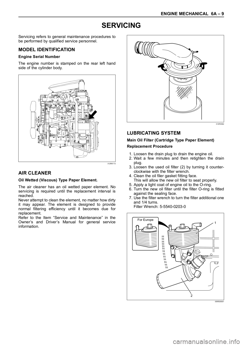
MODEL IDENTIFICATION
Engine Serial Number
The engine number is stamped on the rear left hand
side of the cylinder body.
AIR CLEANER
Oil Wetted (Viscous) Type Paper Element.
The air cleaner has an oil wetted paper element. No
servicing is required until the replacement interval is
reached.
Never attempt to clean the element, no matter how dirty
it may appear. The element is designed to provide
normal filtering efficiency until it becomes due for
replacement.
Refer to the Item “Service and Maintenance” in the
Owner’s and Driver’s Manual for general service
information.
LUBRICATING SYSTEM
Main Oil Filter (Cartridge Type Paper Element)
Replacement Procedure
1. Loosen the drain plug to drain the engine oil.
2. Wait a few minutes and then retighten the drain
plug.
3. Loosen the used oil filter (2) by turning it counter-
clockwise with the filter wrench.
4. Clean the oil filer gasket fitting face.
This will allow the new oil filter to seat properly.
5. Apply a light coat of engine oil to the O-ring.
6. Turn the new oil filter until the filter O-ring is fitted
against the sealing face.
7. Use the filter wrench to turn the filter additional one
and 1/4 turns.
Filter Wrench: 5-5540-0203-0
012RW115
012RW062
For Europe1
2
050R200001
Page 1776 of 6000
ENGINE MECHANICAL 6A – 43
CYLINDER HEAD GASKET
12
13
14
15
8
3
4
5 6
10
11 9
With
spacer type
Without
spacer type
1 7
2
011R200002
Legend
(1) Cylinder Head Noise Insulator Cover
(2) Insulator
(3) Bolt and Gasket
(4) Oil Seal
(5) Gasket
(6) Cylinder Head Cover
(7) Bolt, Stud and Rubber Mounting
(8) Injector Clamp(9) Oil Rail
(10) Injector Assembly
(11) Camshaft Carrier
(12) Cylinder Head Bolt
(13) Cylinder Head Assembly
(14) Cylinder Head Gasket
(15) Cylinder Block
Page 1780 of 6000
ENGINE MECHANICAL 6A – 47
CAMSHAFT
2 1
6With
spacer type
Without
spacer type
13 14
8
12
11
109
3
4
7
5
012R200004
Legend
(1) Nut and Washer
(2) Injector Clamp
(3) Nut
(4) Bolt
(5) Oil Rail Assembly
(6) Spacer (If equipped) and Bolt
(7) Injector Assembly(8) Camshaft
(9) Camshaft Carrier
(10) Plug
(11) Oil Seal
(12) Camshaft Bracket
(13) Gasket
(14) Gasket
Page 1854 of 6000
ENGINE FUEL 6C – 9
INJECTOR
2 1
6With
spacer type
Without
spacer type
8 9
3
4
7
5
Legend
(1) Nut and Washer
(2) Injector Clamp
(3) Nut
(4) Bolt
(5) Oil Rail Assembly
(6) Spacer (If equipped) and Bolt
(7) Injector Assembly(8) Gasket
(9) O-Ring
012R200006