1998 OPEL FRONTERA gas type
[x] Cancel search: gas typePage 1868 of 6000

ENGINE ELECTRICAL 6D – 1
ENGINE ELECTRICAL
CONTENTS
Battery . . . . . . . . . . . . . . . . . . . . . . . . . . . . 6D–1
General Description . . . . . . . . . . . . . . . . 6D–1
Diagnosis . . . . . . . . . . . . . . . . . . . . . . . . 6D–1
On Vehicle Service . . . . . . . . . . . . . . . . . 6D–3
Main Data and Specification . . . . . . . . . . 6D–4
Starting System . . . . . . . . . . . . . . . . . . . . . 6D–5
General Description . . . . . . . . . . . . . . . . 6D–5
On Vehicle Service . . . . . . . . . . . . . . . . . 6D–7
Starter . . . . . . . . . . . . . . . . . . . . . . . . . . 6D–7
Unit Repair . . . . . . . . . . . . . . . . . . . . . . . 6D–8Charging System . . . . . . . . . . . . . . . . . . . . 6D–15
General Description . . . . . . . . . . . . . . . . 6D–15
Diagnosis . . . . . . . . . . . . . . . . . . . . . . . . 6D–16
Unit Repair . . . . . . . . . . . . . . . . . . . . . . . 6D–17
Main Data and Specification . . . . . . . . . . 6D–22
QOS4 Preheating System . . . . . . . . . . . . . . 6D–23
General Description . . . . . . . . . . . . . . . . 6D–23
System Diagram . . . . . . . . . . . . . . . . . . . 6D–23
Inspection of QOS4 System Operation . . 6D–24
BATTERY
GENERAL DESCRIPTION
DIAGNOSIS
There are six battery fluid caps at the top of the battery.
These are covered by a paper label.
The battery is completely sealed except for the six
small vent holes at the side. These vent holes permit
the escape of small amounts of gas generated by the
battery.
This type of battery has the following advantages over
conventional batteries:1. There is no need to add water during the entire
service life of the battery.
2. The battery protects itself against overcharging.
The battery will refuse to accept an excessive
charge.
(A conventional battery will accept an excessive
charge, resulting in gassing and loss of battery
fluid.)
3. The battery is much less vulnerable to self-
discharge than a conventional type battery.
1. VISUAL INSPECTION (Step 1)
Inspect the battery for obvious physical damage, such
as a cracked or broken case, which would permit
electrolyte loss.
Replace the battery if obvious physical damage is
discovered during inspection.
Check for any other physical damage and correct it as
necessary. If not, proceed to Step 2.
2. HYDROMETER CHECK (Step 2)
There is a built-in hydrometer (Charge test indicator) at
the top of the battery. It is designed to be used during
diagnostic procedures.
Before trying to read the hydrometer, carefully clean the
upper battery surface.
If your work area is poorly lit, additional light may be
necessary to read the hydrometer.
a. BLUE RING OR DOT VISIBLE – Go to Step 4.
b. BLUE RING OR DOT NOT VISIBLE – Go to
Step 3.3. FLUID LEVEL CHECK (Step 3)
The fluid level should be between the upper level line
and lower level line on side of the battery.
a. CORRECT FLUID LEVEL – Charge the battery.
b. BELOW LOWER LEVEL – Replace battery.
4. VOLTAGE CHECK (Step 4)
(1) Put voltmeter test leads to battery terminals.
a. VOLTAGE IS 12.4V OR ABOVE – Go to Step 5.
b. VOLTAGE IS UNDER 12.4V – Go to procedure
(2) below.
(2) Determine fast charge amperage from
specification. (See Main Data and Specifications in
this section.)
Fast charge battery for 30 minutes at amperage
rate no higher than specified value.
Take voltage and amperage readings after charge.
a. VOLTAGE IS ABOVE 16V AT BELOW 1/3 OF
AMPERAGE RATE – Replace battery.
Page 1894 of 6000
6E–1 4JX1–TC ENGINE DRIVEABILITY AND EMISSIONS
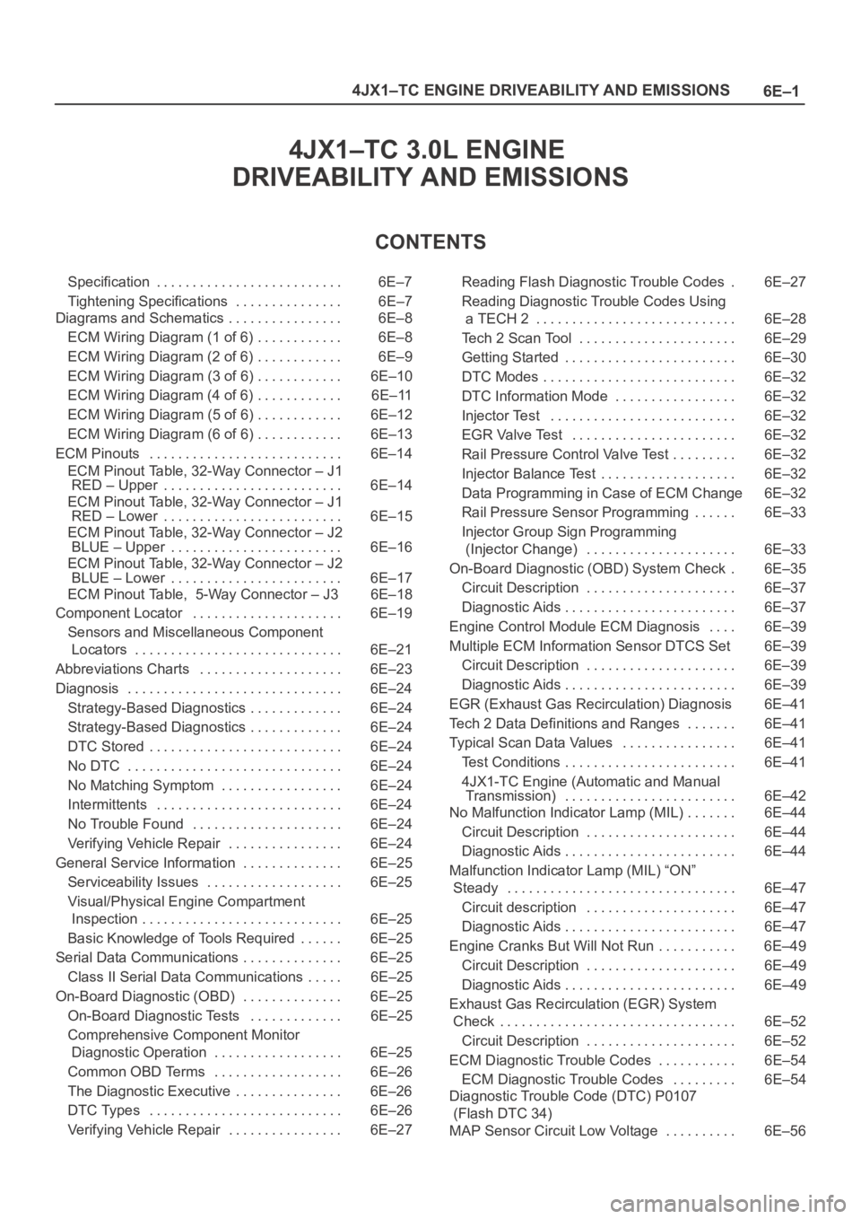
4JX1–TC 3.0L ENGINE
DRIVEABILITY AND EMISSIONS
CONTENTS
Specification 6E–7. . . . . . . . . . . . . . . . . . . . . . . . . .
Tightening Specifications 6E–7. . . . . . . . . . . . . . .
Diagrams and Schematics 6E–8. . . . . . . . . . . . . . . .
ECM Wiring Diagram (1 of 6) 6E–8. . . . . . . . . . . .
ECM Wiring Diagram (2 of 6) 6E–9. . . . . . . . . . . .
ECM Wiring Diagram (3 of 6) 6E–10. . . . . . . . . . . .
ECM Wiring Diagram (4 of 6) 6E–11. . . . . . . . . . . .
ECM Wiring Diagram (5 of 6) 6E–12. . . . . . . . . . . .
ECM Wiring Diagram (6 of 6) 6E–13. . . . . . . . . . . .
ECM Pinouts 6E–14. . . . . . . . . . . . . . . . . . . . . . . . . . .
ECM Pinout Table, 32-Way Connector – J1
RED – Upper 6E–14. . . . . . . . . . . . . . . . . . . . . . . . .
ECM Pinout Table, 32-Way Connector – J1
RED – Lower 6E–15. . . . . . . . . . . . . . . . . . . . . . . . .
ECM Pinout Table, 32-Way Connector – J2
BLUE – Upper 6E–16. . . . . . . . . . . . . . . . . . . . . . . .
ECM Pinout Table, 32-Way Connector – J2
BLUE – Lower 6E–17. . . . . . . . . . . . . . . . . . . . . . . .
ECM Pinout Table, 5-Way Connector – J3 6E–18
Component Locator 6E–19. . . . . . . . . . . . . . . . . . . . .
Sensors and Miscellaneous Component
Locators 6E–21. . . . . . . . . . . . . . . . . . . . . . . . . . . . .
Abbreviations Charts 6E–23. . . . . . . . . . . . . . . . . . . .
Diagnosis 6E–24. . . . . . . . . . . . . . . . . . . . . . . . . . . . . .
Strategy-Based Diagnostics 6E–24. . . . . . . . . . . . .
Strategy-Based Diagnostics 6E–24. . . . . . . . . . . . .
DTC Stored 6E–24. . . . . . . . . . . . . . . . . . . . . . . . . . .
No DTC 6E–24. . . . . . . . . . . . . . . . . . . . . . . . . . . . . .
No Matching Symptom 6E–24. . . . . . . . . . . . . . . . .
Intermittents 6E–24. . . . . . . . . . . . . . . . . . . . . . . . . .
No Trouble Found 6E–24. . . . . . . . . . . . . . . . . . . . .
Verifying Vehicle Repair 6E–24. . . . . . . . . . . . . . . .
General Service Information 6E–25. . . . . . . . . . . . . .
Serviceability Issues 6E–25. . . . . . . . . . . . . . . . . . .
Visual/Physical Engine Compartment
Inspection 6E–25. . . . . . . . . . . . . . . . . . . . . . . . . . . .
Basic Knowledge of Tools Required 6E–25. . . . . .
Serial Data Communications 6E–25. . . . . . . . . . . . . .
Class II Serial Data Communications 6E–25. . . . .
On-Board Diagnostic (OBD) 6E–25. . . . . . . . . . . . . .
On-Board Diagnostic Tests 6E–25. . . . . . . . . . . . .
Comprehensive Component Monitor
Diagnostic Operation 6E–25. . . . . . . . . . . . . . . . . .
Common OBD Terms 6E–26. . . . . . . . . . . . . . . . . .
The Diagnostic Executive 6E–26. . . . . . . . . . . . . . .
DTC Types 6E–26. . . . . . . . . . . . . . . . . . . . . . . . . . .
Verifying Vehicle Repair 6E–27. . . . . . . . . . . . . . . . Reading Flash Diagnostic Trouble Codes 6E–27.
Reading Diagnostic Trouble Codes Using
a TECH 2 6E–28. . . . . . . . . . . . . . . . . . . . . . . . . . . .
Tech 2 Scan Tool 6E–29. . . . . . . . . . . . . . . . . . . . . .
Getting Started 6E–30. . . . . . . . . . . . . . . . . . . . . . . .
DTC Modes 6E–32. . . . . . . . . . . . . . . . . . . . . . . . . . .
DTC Information Mode 6E–32. . . . . . . . . . . . . . . . .
Injector Test 6E–32. . . . . . . . . . . . . . . . . . . . . . . . . .
EGR Valve Test 6E–32. . . . . . . . . . . . . . . . . . . . . . .
Rail Pressure Control Valve Test 6E–32. . . . . . . . .
Injector Balance Test 6E–32. . . . . . . . . . . . . . . . . . .
Data Programming in Case of ECM Change 6E–32
Rail Pressure Sensor Programming 6E–33. . . . . .
Injector Group Sign Programming
(Injector Change) 6E–33. . . . . . . . . . . . . . . . . . . . .
On-Board Diagnostic (OBD) System Check 6E–35.
Circuit Description 6E–37. . . . . . . . . . . . . . . . . . . . .
Diagnostic Aids 6E–37. . . . . . . . . . . . . . . . . . . . . . . .
Engine Control Module ECM Diagnosis 6E–39. . . .
Multiple ECM Information Sensor DTCS Set 6E–39
Circuit Description 6E–39. . . . . . . . . . . . . . . . . . . . .
Diagnostic Aids 6E–39. . . . . . . . . . . . . . . . . . . . . . . .
EGR (Exhaust Gas Recirculation) Diagnosis 6E–41
Tech 2 Data Definitions and Ranges 6E–41. . . . . . .
Typical Scan Data Values 6E–41. . . . . . . . . . . . . . . .
Test Conditions 6E–41. . . . . . . . . . . . . . . . . . . . . . . .
4JX1-TC Engine (Automatic and Manual
Transmission) 6E–42. . . . . . . . . . . . . . . . . . . . . . . .
No Malfunction Indicator Lamp (MIL) 6E–44. . . . . . .
Circuit Description 6E–44. . . . . . . . . . . . . . . . . . . . .
Diagnostic Aids 6E–44. . . . . . . . . . . . . . . . . . . . . . . .
Malfunction Indicator Lamp (MIL) “ON”
Steady 6E–47. . . . . . . . . . . . . . . . . . . . . . . . . . . . . . . .
Circuit description 6E–47. . . . . . . . . . . . . . . . . . . . .
Diagnostic Aids 6E–47. . . . . . . . . . . . . . . . . . . . . . . .
Engine Cranks But Will Not Run 6E–49. . . . . . . . . . .
Circuit Description 6E–49. . . . . . . . . . . . . . . . . . . . .
Diagnostic Aids 6E–49. . . . . . . . . . . . . . . . . . . . . . . .
Exhaust Gas Recirculation (EGR) System
Check 6E–52. . . . . . . . . . . . . . . . . . . . . . . . . . . . . . . . .
Circuit Description 6E–52. . . . . . . . . . . . . . . . . . . . .
ECM Diagnostic Trouble Codes 6E–54. . . . . . . . . . .
ECM Diagnostic Trouble Codes 6E–54. . . . . . . . .
Diagnostic Trouble Code (DTC) P0107
(Flash DTC 34)
MAP Sensor Circuit Low Voltage 6E–56. . . . . . . . . .
Page 2110 of 6000
6E–217 4JX1–TC ENGINE DRIVEABILITY AND EMISSIONS
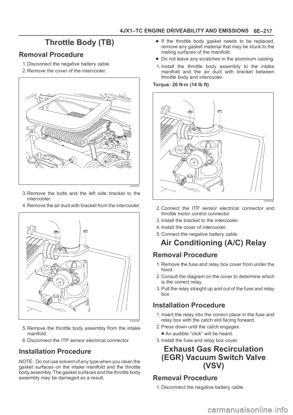
Throttle Body (TB)
Removal Procedure
1. Disconnect the negative battery cable.
2. Remove the cover of the intercooler.
035RW051
3. Remove the bolts and the left side bracket to the
intercooler.
4 . R e m o v e t h e a i r d u c t w i t h b r a c k e t f r o m t h e i n t e r c o o l e r.
035RW086
5. Remove the throttle body assembly from the intake
manifold.
6. Disconnect the ITP sensor electrical connector.
Installation Procedure
NOTE: Do not use solvent of any type when you clean the
gasket surfaces on the intake manifold and the throttle
body assembly. The gasket surfaces and the throttle body
assembly may be damaged as a result.
If the throttle body gasket needs to be replaced,
remove any gasket material that may be stuck to the
mating surfaces of the manifold.
Do not leave any scratches in the aluminum casting.
1. Install the throttle body assembly to the intake
manifold and the air duct with bracket between
throttle body and intercooler.
Torque: 20 Nꞏm (14 Ib ft)
035RW086
2. Connect the ITP sensor electrical connector and
throttle motor control connector.
3. Install the bracket to the intercooler.
4. Install the cover of intercooler.
5. Connect the negative battery cable.
Air Conditioning (A/C) Relay
Removal Procedure
1. Remove the fuse and relay box cover from under the
hood.
2. Consult the diagram on the cover to determine which
is the correct relay.
3. Pull the relay straight up and out of the fuse and relay
box.
Installation Procedure
1. Insert the relay into the correct place in the fuse and
relay box with the catch slot facing forward.
2. Press down until the catch engages.
An audible “click” will be heard.
3. Install the fuse and relay box cover.
Exhaust Gas Recirculation
(EGR) Vacuum Switch Valve
(VSV)
Removal Procedure
1. Disconnect the negative battery cable.
Page 2125 of 6000

6F – 2 ENGINE EXHAUST
GENERAL DESCRIPTION
150RW070
When inspecting or replacing exhaust system
components, make sure there is adequate clearance
from all points on the underbody to prevent overheating
of the floor pan and possible damage to the passenger
compartment insulation and trim materials.
Check complete exhaust system and nearby body
areas and rear compartment lid for broken, damaged,
missing or mispositioned parts, open seams, holes
loose connections or other deterioration which could
permit exhaust fumes to seep into the rear
compartment or passenger compartment. Dust or water
in the rear compartment may be an indication of a
problem in one of these areas. Any faulty areas should
be corrected immediately.HANGERS
Various types of hangers are used to support exhaust
system(s). These include conventional rubber straps,
rubber rings, and rubber blocks.
The installation of exhaust system supports is very
important, as improperly installed supports can cause
annoying vibrations which can be difficult to diagnose.
GASKET
The gasket must be replaced whenever a new exhaust
pipe, muffler or exhaust throttle is installed.
Page 3461 of 6000
SUPPLEMENTAL RESTRAINT SYSTEM 9J–24
NOTE: Ensure that the pigtail adapter is firmly seated into
the pretensioner seat belt assembly connector. Failure to
fully seat the connectors may leave the shorting bar
located in the pretensioner seat belt assembly connector
functioning (shorted) and may result in nondeployment of
the pretensioner seat belt assembly.
13. Separate the two banana plugs on the SRS
deployment harness.
NOTE: When the pretensioner seat belt deploys, the
rapid gas expansion will create a substantial noise. Notify
all people in the immediate area that you intend to deploy
the pretensioner seat belt.
WARNING: DEPLOYMENT HARNESS SHALL
REMAIN SHORTED AND NOT BE CONNECTED TO A
POWER SOURCE UNTIL THE PRETENSIONER SEAT
BELT IS TO BE DEPLOYED. THE PRETENSIONER
SEAT BELT ASSEMBLY WILL IMMEDIATELY
DEPLOY THE PRETENSIONER SEAT BELT WHEN A
POWER SOURCE IS CONNECTED TO IT.
CONNECTING THE DEPLOYMENT HARNESS TO
THE POWER SOURCE SHOULD ALWAYS BE THE
LAST STEP IN THE PRETENSIONER SEAT BELT
ASSEMBLY DEPLOYMENT PROCEDURE. FAILURE
TO FOLLOW PROCEDURES IN THE ORDER LISTED
MAY RESULT IN PERSONAL INJURY.
14. Connect the SRS deployment harness wires to the
power source to immediately deploy the pretensioner
seat belt. Recommended application: 12 volts
minimum, 2 amps minimum. A vehicle battery is
suggested.
15. Disconnect the SRS deployment harness from the
power source.
16. Short the two SRS deployment harness leads
together by fully seating one banana plug into the
other.
17. In the unlikely event that the pretensioner seat belt
assembly did not deploy after following these
procedures, proceed immediately with Steps 21
through 24. If the pretensioner seat belt assembly did
deploy, proceed with Steps 15 through 20.
18.
WARNING: SAFETY PRECAUTIONS MUST BE
OBSERVED WHEN HANDING A DEPLOYED
PRETENSIONER SEAT BELT ASSEMBLY. AFTER
DEPLOYMENT, THE METAL SURFACES OF THE
PRETENSIONER SEAT BELT ASSEMBLY WILL BE
VERY HOT. ALLOW THE INFLATOR MODULE TO
COOL BEFORE HANDLING ANY METAL PORTION
OF IT. DO NOT PLACE THE DEPLOYED
PRETENSIONER SEAT BELT ASSEMBLY NEAR ANY
FLAMMABLE OBJECTS. FAILURE TO FOLLOW
PROCEDURES MAY RESULT IN FIRE OR PERSONAL
INJURY.
AFTER A DRIVER PRETENSIONER SEAT BELT
ASSEMBLY HAS BEEN DEPLOYED, THE METAL
CANISTER AND SURROUNDING AREAS OF THE
DRIVER PRETENSIONER SEAT BELT ASSEMBLY
WILL BE VERY HOT. DO NOT TOUCH THE METAL
AREAS OF THE PRETENSIONER SEAT BELT
ASSEMBLY FOR ABOUT TEN MINUTES AFTER
DEPLOYMENT. IF THE DEPLOYED PRETENSIONERSEAT BELT ASSEMBLY MUST BE MOVED BEFORE
IT IS COOL, WEAR GLOVES AND HANDLE BY THE
PRETENSIONER SEAT BELT OR TRIM COVER.
19. Disconnect the pigtail adapter from the pretensioner
seat belt assembly as soon after deployment as
possible. This will prevent damage to the pigtail
adapter or SRS deployment harness due to possible
contact with the hot pretensioner seat belt assembly
canister. The pigtail adapter can be reused. They
should, however, be inspected for damage after each
deployment and replaced if necessary.
20. Dispose of the deployed pretensioner seat belt
assembly through normal refuse channels after it has
cooled for at least 30 minutes.
21. Wash your hands with mild soap and water afterward.
NOTE: The remaining steps are to be followed in the
unlikely event that the pretensioner seat belt assembly
did not deploy after following these procedures.
22. Ensure that the SRS deployment harness has been
disconnected from the power source and that its two
banana plugs have been shorted together by fully
seating one banana plug into the other.
23. Disconnect the pigtail adapter from the pretensioner
seat belt assembly.
24. Remove the undeployed pretensioner seat belt from
the special tool.
WARNING: W H E N S TO R I N G A L I V E
PRETENSIONER SEAT BELT ASSEMBLY OR WHEN
LEAVING A LIVE INFLATOR MODULE UNATTENDED
ON A BENCH OR OTHER SURFACE, ALWAYS PUT
THE PRETENSIONER SEAT BELT HORIZONTAL
PLACE. THIS IS NECESSARY SO THAT A FREE
SPACE IS PROVIDED TO ALLOW THE
PRETENSIONER SEAT BELT TO SHRINK IN THE
UNLIKELY EVENT OF ACCIDENTAL DEPLOYMENT.
FAILURE TO FOLLOW PROCEDURES MAY RESULT
IN PERSONAL INJURY.
25.Temporarily store the pretensioner seat belt
assembly with its deployment device facing up, away
from the surface upon which it rests.
Deployment Inside Vehicle (Pretensioner
Seat Belt Vehicle Scrapping Procedure)
Deployment inside vehicle is proper when the vehicle is to
be destroyed. This includes, but is not limited to, the
following situations:
1. The vehicle has completed its useful life.
2. The vehicle has been damaged beyond repair in a
nondeployment type accident.
3. The vehicle has been stripped or damaged beyond
repair in a theft.
NOTE: The vehicle will be salvaged for component parts
to be used on a vehicle with a different Vehicle
Identification Number (VIN) as opposed to being rebuilt
as same VIN. Never use pretensioner seat belt
components from another vehicle.
WARNING: FAILURE TO FOLLOW PROCEDURES IN
THE ORDER LISTED COULD RESULT IN PERSONAL
INJURY. NEVER CONNECT DEPLOYMENT WIRES
Page 3769 of 6000
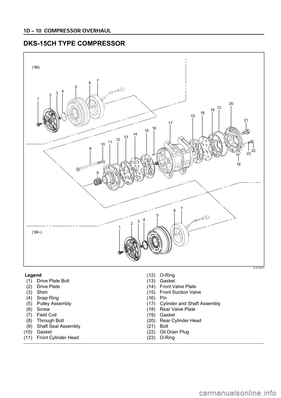
Legend
(1) Drive Plate Bolt
(2) Drive Plate
(3) Shim
(4) Snap Ring
(5) Pulley Assembly
(6) Screw
(7) Field Coil
(8) Through Bolt
(9) Shaft Seal Assembly
(10) Gasket
(11) Front Cylinder Head(12) O-Ring
(13) Gasket
(14) Front Valve Plate
(15) Front Suction Valve
(16) Pin
(17) Cylinder and Shaft Assembly
(18) Rear Valve Plate
(19) Gasket
(20) Rear Cylinder Head
(21) Bolt
(22) Oil Drain Plug
(23) O-Ring
DKS-15CH TYPE COMPRESSOR
16
23 2122 6
7
45
321 (’98)
(’99~)
67
45
321
8
910111213141516
17
1518191220
871RY00015
Page 3971 of 6000
4A2A–2
DIFFERENTIAL (REAR 220mm)
General Description
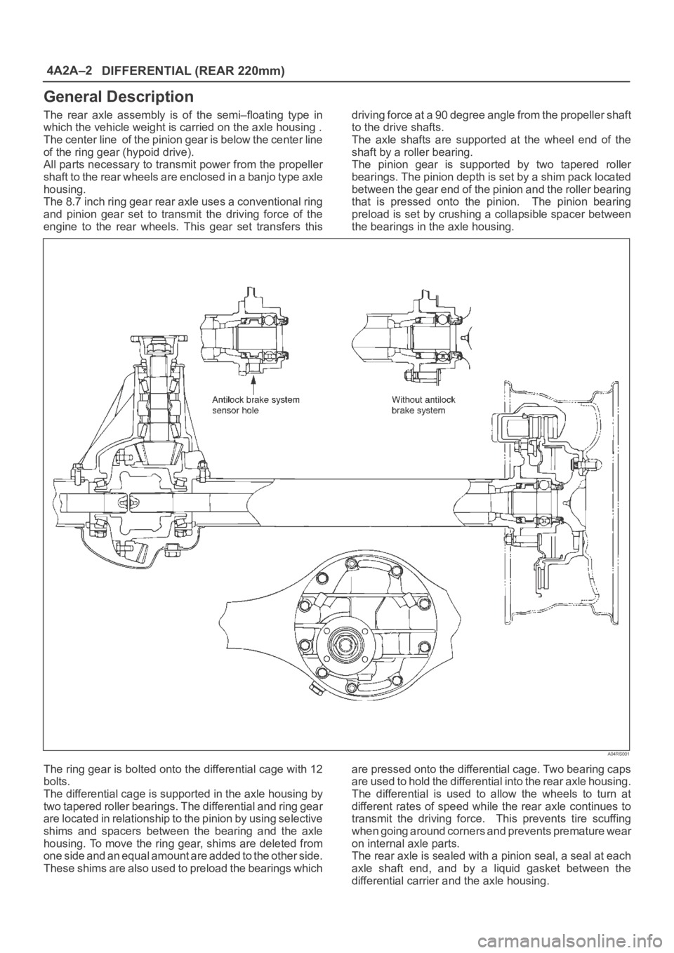
The rear axle assembly is of the semi–floating type in
which the vehicle weight is carried on the axle housing .
The center line of the pinion gear is below the center line
of the ring gear (hypoid drive).
All parts necessary to transmit power from the propeller
shaft to the rear wheels are enclosed in a banjo type axle
housing.
The 8.7 inch ring gear rear axle uses a conventional ring
and pinion gear set to transmit the driving force of the
engine to the rear wheels. This gear set transfers thisdriving force at a 90 degree angle from the propeller shaft
to the drive shafts.
The axle shafts are supported at the wheel end of the
shaft by a roller bearing.
The pinion gear is supported by two tapered roller
bearings. The pinion depth is set by a shim pack located
between the gear end of the pinion and the roller bearing
that is pressed onto the pinion. The pinion bearing
preload is set by crushing a collapsible spacer between
the bearings in the axle housing.
A04RS001
The ring gear is bolted onto the differential cage with 12
bolts.
The differential cage is supported in the axle housing by
two tapered roller bearings. The differential and ring gear
are located in relationship to the pinion by using selective
shims and spacers between the bearing and the axle
housing. To move the ring gear, shims are deleted from
one side and an equal amount are added to the other side.
These shims are also used to preload the bearings whichare pressed onto the differential cage. Two bearing caps
are used to hold the differential into the rear axle housing.
The differential is used to allow the wheels to turn at
different rates of speed while the rear axle continues to
transmit the driving force. This prevents tire scuffing
when going around corners and prevents premature wear
on internal axle parts.
The rear axle is sealed with a pinion seal, a seal at each
axle shaft end, and by a liquid gasket between the
differential carrier and the axle housing.
Page 4010 of 6000
DIFFERENTIAL (REAR 244mm)
4A2B–3
General Description
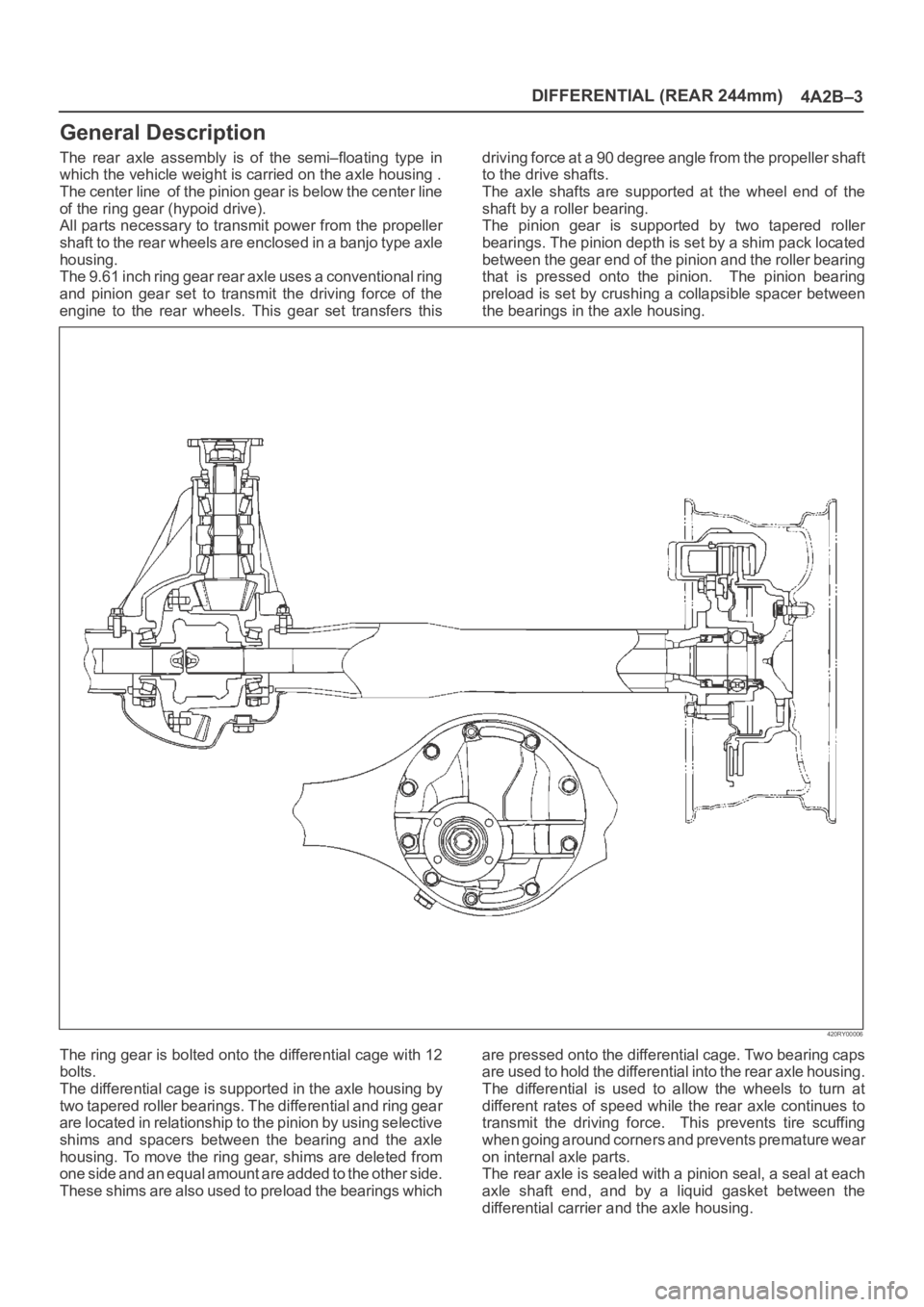
The rear axle assembly is of the semi–floating type in
which the vehicle weight is carried on the axle housing .
The center line of the pinion gear is below the center line
of the ring gear (hypoid drive).
All parts necessary to transmit power from the propeller
shaft to the rear wheels are enclosed in a banjo type axle
housing.
The 9.61 inch ring gear rear axle uses a conventional ring
and pinion gear set to transmit the driving force of the
engine to the rear wheels. This gear set transfers thisdriving force at a 90 degree angle from the propeller shaft
to the drive shafts.
The axle shafts are supported at the wheel end of the
shaft by a roller bearing.
The pinion gear is supported by two tapered roller
bearings. The pinion depth is set by a shim pack located
between the gear end of the pinion and the roller bearing
that is pressed onto the pinion. The pinion bearing
preload is set by crushing a collapsible spacer between
the bearings in the axle housing.
420RY00006
The ring gear is bolted onto the differential cage with 12
bolts.
The differential cage is supported in the axle housing by
two tapered roller bearings. The differential and ring gear
are located in relationship to the pinion by using selective
shims and spacers between the bearing and the axle
housing. To move the ring gear, shims are deleted from
one side and an equal amount are added to the other side.
These shims are also used to preload the bearings whichare pressed onto the differential cage. Two bearing caps
are used to hold the differential into the rear axle housing.
The differential is used to allow the wheels to turn at
different rates of speed while the rear axle continues to
transmit the driving force. This prevents tire scuffing
when going around corners and prevents premature wear
on internal axle parts.
The rear axle is sealed with a pinion seal, a seal at each
axle shaft end, and by a liquid gasket between the
differential carrier and the axle housing.