1998 OPEL FRONTERA battery replacement
[x] Cancel search: battery replacementPage 3341 of 6000
8H–2SECURITY AND LOCKS
Service Precaution
WARNING: IF SO EQUIPPED WITH A
SUPPLEMENTAL RESTRAINT SYSTEM (SRS),
REFER TO THE SRS COMPONENT AND WIRING
LOCATION VIEW IN ORDER TO DETERMINE
WHETHER YOU ARE PERFORMING SERVICE ON OR
NEAR THE SRS COMPONENTS OR THE SRS
WIRING. WHEN YOU ARE PERFORMING SERVICE
ON OR NEAR THE SRS COMPONENTS OR THE SRS
WIRING, REFER TO THE SRS SERVICE
INFORMATION. FAILURE TO FOLLOW WARNINGS
COULD RESULT IN POSSIBLE AIR BAG
DEPLOYMENT, PERSONAL INJURY, OR
OTHERWISE UNNEEDED SRS SYSTEM REPAIRS.CAUTION: Always use the correct fastener in the
proper location. When you replace a fastener, use
ONLY the exact part number for that application.
ISUZU will call out those fasteners that require a
replacement after removal. ISUZU will also call out
the fasteners that require thread lockers or thread
sealant. UNLESS OTHERWISE SPECIFIED, do not
use supplemental coatings (Paints, greases, or other
corrosion inhibitors) on threaded fasteners or
fastener joint interfaces. Generally, such coatings
adversely affect the fastener torque and the joint
clamping force, and may damage the fastener. When
you install fasteners, use the correct tightening
sequence and specifications. Following these
instructions can help you avoid damage to parts and
systems.
Front Door Lock Assembly
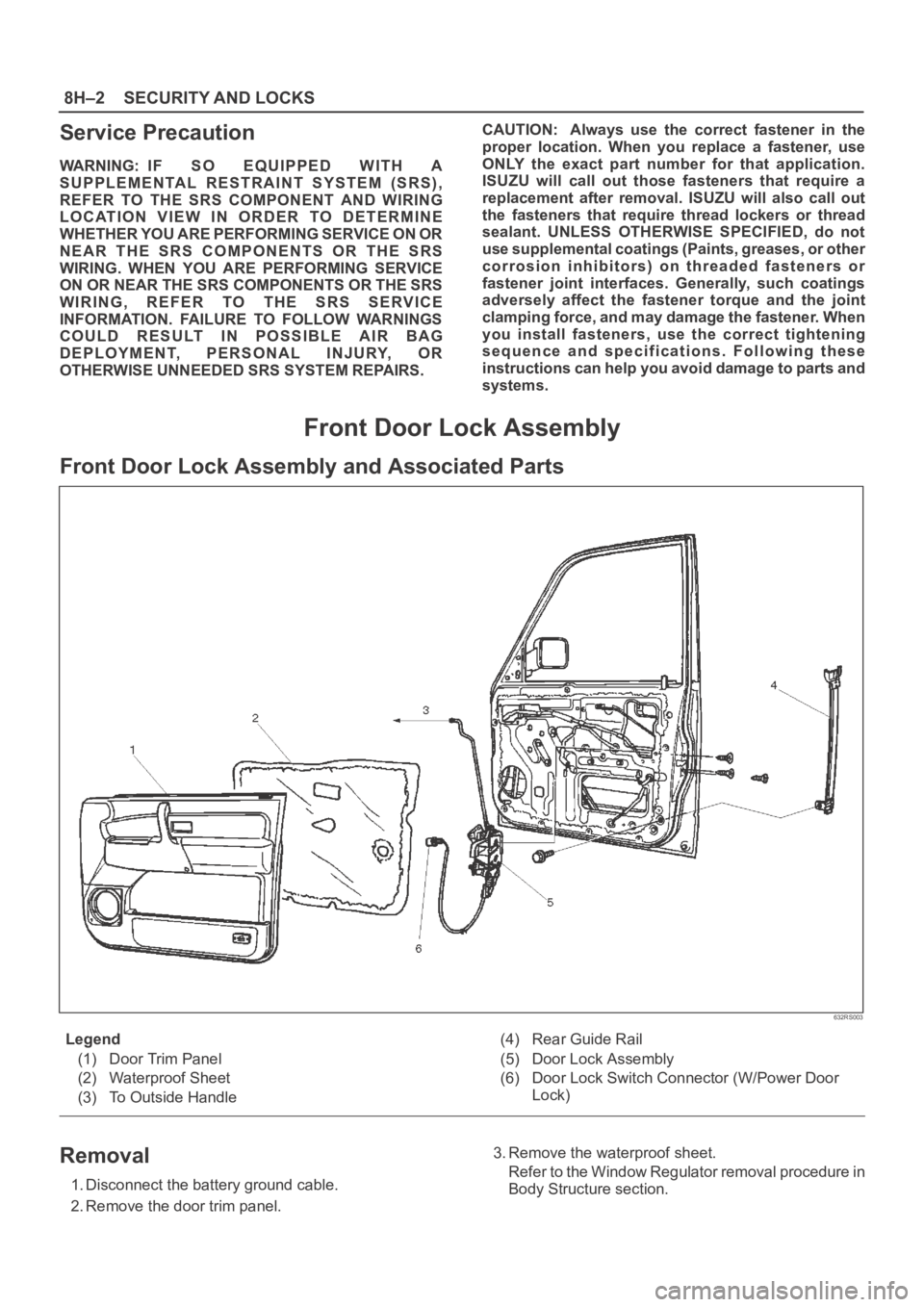
Front Door Lock Assembly and Associated Parts
632RS003
Legend
(1) Door Trim Panel
(2) Waterproof Sheet
(3) To Outside Handle(4) Rear Guide Rail
(5) Door Lock Assembly
(6) Door Lock Switch Connector (W/Power Door
Lock)
Removal
1. Disconnect the battery ground cable.
2. Remove the door trim panel.3. Remove the waterproof sheet.
Refer to the Window Regulator removal procedure in
Body Structure section.
Page 3366 of 6000
SECURITY AND LOCKS8H–27
StepNo Ye s Action
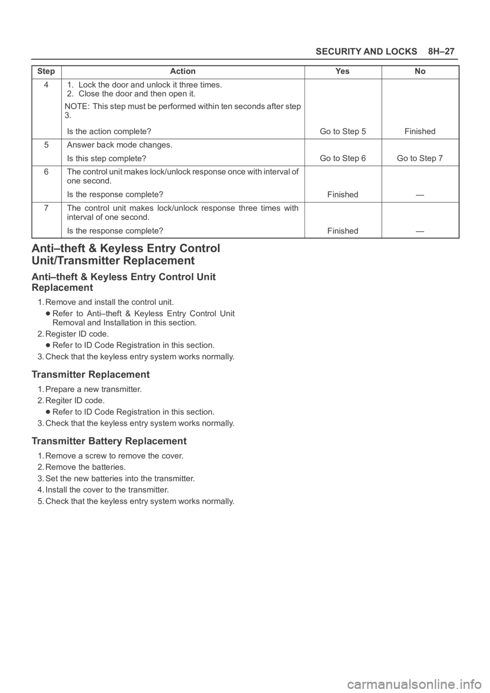
41. Lock the door and unlock it three times.
2. Close the door and then open it.
NOTE: This step must be performed within ten seconds after step
3.
Is the action complete?
Go to Step 5Finished
5Answer back mode changes.
Is this step complete?
Go to Step 6Go to Step 7
6The control unit makes lock/unlock response once with interval of
one second.
Is the response complete?
Finished—
7The control unit makes lock/unlock response three times with
interval of one second.
Is the response complete?
Finished—
Anti–theft & Keyless Entry Control
Unit/Transmitter Replacement
Anti–theft & Keyless Entry Control Unit
Replacement
1. Remove and install the control unit.
Refer to Anti–theft & Keyless Entry Control Unit
Removal and Installation in this section.
2. Register ID code.
Refer to ID Code Registration in this section.
3. Check that the keyless entry system works normally.
Transmitter Replacement
1. Prepare a new transmitter.
2. Regiter ID code.
Refer to ID Code Registration in this section.
3. Check that the keyless entry system works normally.
Transmitter Battery Replacement
1. Remove a screw to remove the cover.
2. Remove the batteries.
3. Set the new batteries into the transmitter.
4. Install the cover to the transmitter.
5. Check that the keyless entry system works normally.
Page 3447 of 6000
SUPPLEMENTAL RESTRAINT SYSTEM 9J–10
Accident With Deployment – Component
Replacement And Inspections
Certain SRS components must be replaced or inspected
for damage after a frontal crash involving air bag
deployment. Those components are:
Air bag assembly
SDM
CAUTION: Refer to “SDM Replacement Guidelines”
below for important information on SDM
replacement in both deployment and non
deployment crashes.
SRS coil assembly — Inspect wiring and connector
for any signs of scorching, melting, or damage due to
excessive heat. Replace if damaged. Refer to
section “SRS Coil Assembly” in this manual.
Accident With or Without Deployment –
Component Inspection
Certain SRS system components and rotation parts must
be inspected after any crash, whether the air bag
deployed or not. Those components are:
Steering column — Refer to Inspection Required
“After an Accident” in this manual.
Knee bolsters and mounting points — Inspect for any
distortion, bending, cracking, or other damage.
I/P steering column reinforcement plate — Inspect for
any distortion, bending, cracking, or other damage.
I/P braces — Inspect for any distortion, bending,
cracking, or other damage.
Seat belts and mounting points — Refer to “Seat
Belts” in Section “Seat Belt” of this workshop manual.
SDM Replacement Guidelines
SDM replacement policy requires replacement of SDM,
after crash involving air bag deployment when “SRS
Warning Lamp” turn “ON”, “SRS Diagnosis” should be
done according to Section “Restraint Control System.”
If accident without deployment air bag, it is not necessary
replacement of SDM when do not indicate to replace the
SDM by scan tool after SRS system check.
Wiring Damage
If any SRS wire harness is damaged, it should be
replaced. Don’t repair SRS harness. It is replace only.
SRS Connector (Plastic Body And
Terminal Metal Pin) Damage
If any connector or terminal in the SRS wire harness
(except pigtails) is damaged, it should be replaced.
SRS Wire Pigtail Damage
If the wiring pigtail (a wire or wires attached directly to the
device, not by a connector) is damaged, the entire
component (with pigtail) must be replaced. Examples of
“pigtail” components are the driver air bag assembly, the
passenger air bag assembly, and the SRS coil assembly.
On–Vehicle Service
Service Precaution
WARNING: WHEN PERFORMING SERVICE ON OR
AROUND SRS COMPONENTS OR SRS WIRING,
FOLLOW THE PROCEDURES LISTED BELOW TO
TEMPORARILY DISABLE THE SRS. FAILURE TO
FOLLOW PROCEDURES COULD RESULT IN
POSSIBLE AIR BAG DEPLOYMENT, PERSONAL
INJURY OR OTHERWISE UNNEEDED SRS REPAIRS.
The SDM in Driver–Passenger SRS can maintain
sufficient voltage to cause a deployment for up to 15
seconds after the ignition switch is turned “OFF,” the
battery is disconnected, or the fuse powering the SDM is
removed.
Many of the service procedures require removal of the
“C–21” fuse, and disconnection of the air bag assembly
from the deployment loop to avoid an accidental
deployment. If the air bag assembly is disconnected from
the deployment loop as noted in the “Disabling the SRS”
procedure that follows, service can begin immediately
without waiting for the 15 second time period to expire.
Disabling The SRS
Removal
Turn the ignition switch to “LOCK” and remove key.
1. Remove SRS fuse C–21, from left dash side lower
fuse block or disconnect battery.
2. Disconnect yellow 2–pin connector at the base of
steering column.
3. Remove glove box assembly, refer to “Passenger Air
Bag Assembly Replacement” in this manual.
4. Disconnect yellow 2–pin connector behind the glove
box assembly.
CAUTION: With the “C–21” fuse removed and
ignition switch “ON”, the “AIR BAG” warning lamp
will be “ON”. This is normal operation and does not
indicate an SRS malfunction.
Enabling The SRS
Installation
CAUTION: Never use the air bag assembly from
another vehicle. Use only the air bag assembly for
Trooper.
Turn ignition switch to “LOCK” and remove key.
1. Connect yellow 2–pin connector passenger air bag
assembly.
2. Install glove box assembly. Refer to “Passenger air
bag assembly replacement” in this manual.
3. Connect yellow 2–pin connector at the base of
steering column.
4. Install “AIR BAG” fuse C–21 to left dash side lower
fuse block or connect battery.
Turn ignition switch to “ON” and verify that the “AIR BAG”
warning lamp turn on 3.5 seconds and then turns “OFF.” If
it does not operate as described, perform the “SRS
Diagnostic System Check” in this manual.
Page 3454 of 6000
SUPPLEMENTAL RESTRAINT SYSTEM9J–17
COOL BEFORE HANDLING ANY METAL PORTION
OF IT. DO NOT PLACE THE DEPLOYED INFLATOR
MODULE NEAR ANY FLAMMABLE OBJECTS.
FAILURE TO FOLLOW PROCEDURES MAY RESULT
IN FIRE OR PERSONAL INJURY. AFTER AN AIR BAG
ASSEMBLY HAS BEEN DEPLOYED, THE METAL
CANISTER AND SURROUNDING AREAS OF THE AIR
BAG ASSEMBLY WILL BE HOT. DO NOT TOUCH THE
METAL AREAS OF THE AIR BAG ASSEMBLY FOR
ABOUT THIRTY MINUTES AFTER DEPLOYMENT. IF
THE DEPLOYED AIR BAG ASSEMBLY MUST BE
MOVED BEFORE IT IS COOL, WEAR GLOVES AND
HANDLE BY THE AIR BAG ITSELF.
21. Disconnect the pigtail adapter from the air bag
assembly as soon after deployment as possible to
avoid damage to the pigtail adapter or SRS
deployment harness from contacting the hot air bag
assembly canister. The pigtail adapter and SRS
deployment harness are designed to be reused.
They should, however, be inspected for damage after
each deployment and replaced if necessary.
22. Dispose of the deployed air bag assembly through
normal refuse channels after it has cooled for at least
30 minutes.
23. Wash your hands with mild soap and water afterward.
NOTE: The remaining steps are to be followed in the
unlikely event that the air bag assembly did not deploy
after following the above procedures.
24. Ensure that the SRS deployment harness has been
disconnected from the power source and that its two
banana plugs have been shorted together by fully
seating one banana plug into the other.
25. Disconnect the pigtail adapter from the air bag
assembly.
WARNING: WHEN STORING A LIVE AIR BAG
ASSEMBLY OR WHEN LEAVING A LIVE AIR BAG
ASSEMBLY UNATTENDED ON A BENCH OR OTHER
SURFACE, ALWAYS FACE THE BAG UP AND AWAY
FROM THE SURFACE. THIS IS NECESSARY SO
THAT A FREE SPACE IS PROVIDED TO ALLOW THE
AIR BAG TO EXPAND IN THE UNLIKELY EVENT OF
ACCIDENTAL DEPLOYMENT. FAILURE TO FOLLOW
PROCEDURES MAY RESULT IN PERSONAL INJURY.
26. Temporarily store the air bag assembly with the bag
facing up, away from the surface upon which it rests.
Deployment Outside Vehicle (Fixing Air
Bag on Tire)
Read and understand the items of “CAUTIONS ABOUT
AIR BAG DEPLOYMENT AND DISPOSAL
PROCEDURES” and “Usage of Deployment Tool” for
safe deployment of air bag.
1. Remove air bag assembly from vehicle. Refer to air
bag assembly Removal “in this section”.2. Inspect J–41434 Supplemental Restraint System
(SRS) Deployment Harness and appropriate pigtail
adapter for damage. If harness or pigtail is damaged,
discard and obtain a replacement.
3. Extend double pole extension cord to a position far
away 10 m (33 feet) from the air bag assembly.
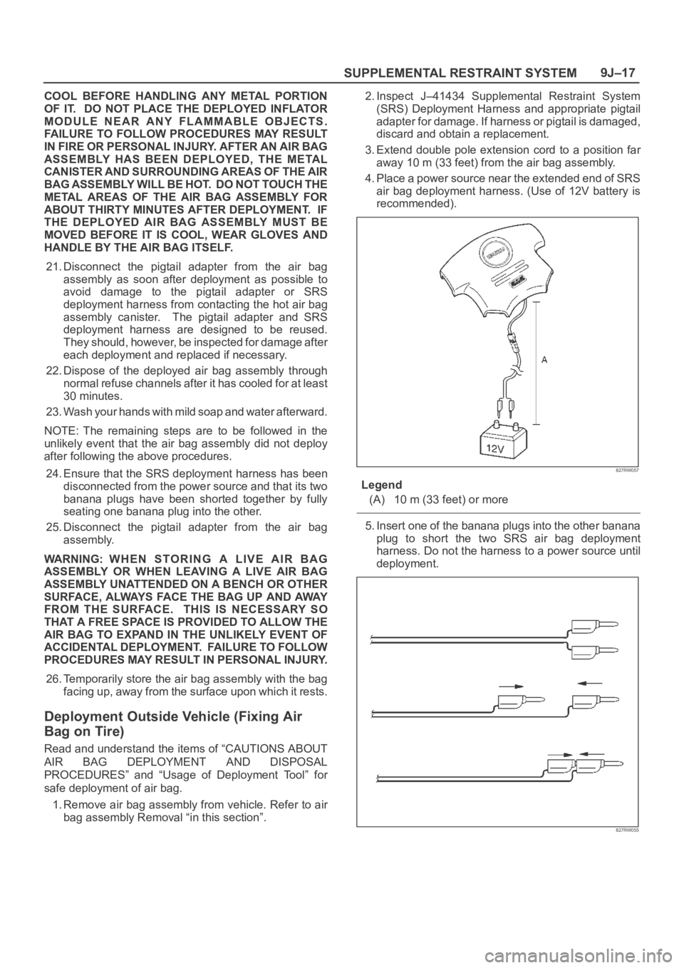
4. Place a power source near the extended end of SRS
air bag deployment harness. (Use of 12V battery is
recommended).
827RW057
Legend
(A) 10 m (33 feet) or more
5. Insert one of the banana plugs into the other banana
plug to short the two SRS air bag deployment
harness. Do not the harness to a power source until
deployment.
827RW055
Page 3467 of 6000
SUPPLEMENTAL RESTRAINT SYSTEM 9J–30
Service Precautions for SRS
Component Service
CAUTION: When fasteners are removed, always
reinstall them at the same location from which they
were removed. If a fastener needs to be replaced, use
the correct part number fastener for that application.
If the correct part number fastener is not available, a
fastener of equal size and strength (or stronger) may
be used. fasteners that are not reused, and those
requiring thread locking compound will be called
out. The correct torque value must be used when
installing fasteners that require it. If the above
conditions are not followed, parts or system damage
could result.
WARNING: WHEN PERFORMING SERVICE ON OR
AROUND SRS COMPONENTS OR SRS WIRING,
FOLLOW THE PROCEDURES LISTED BELOW TO
TEMPORARILY DISABLE THE SRS. FAILURE TO
FOLLOW PROCEDURES COULD RESULT IN
POSSIBLE AIR BAG DEPLOYMENT, PERSONAL
INJURY OR OTHERWISE UNNEEDED SRS REPAIRS.
The SDM in Driver–Passenger SRS can maintain
sufficient voltage to cause a deployment for up to 15
seconds after the ignition switch is turned “OFF,” the
battery is disconnected, or the fuse powering the SDM is
removed.
Many of the service procedures require removal of the
“C–21” fuse, and disconnection of the air bag assembly
from the deployment loop to avoid an accidental
deployment. If the air bag assembly is disconnected from
the deployment loop as noted in the “Disabling the SRS”
procedure that follows, service can begin immediately
without waiting for the 15 second time period to expire.
Disabling The SRS
Removal
Turn the ignition switch to “OFF” and turn the steering
wheel so that the vehicle’s wheels are pointing straight
ahead.
1. Remove SRS fuse “C–21” from left dash side lower
fuse block or disconnect battery.
2. Disconnect yellow 2–pin connector at the base of
steering column.
3 . R e m o v e g l o v e b o x a s s e m b l y ; R e f e r t o “ P a s s e n g e r a i r
bag assembly replacement” in this section.
4. Disconnect passenger air bag assembly yellow 2–pin
connector behind the glove box assembly.
CAUTION: W i t h t h e “ C – 2 1 ” f u s e r e m o v e d a n d
ignition switch “ON,” the “AIR BAG” warning lamp
will be “ON.” This is normal operation and does not
indicate an SRS malfunction.
Enabling The SRS
Installation
Turn ignition switch to “LOCK” and remove key.
1. Connect yellow 2–pin connector passenger air bag
assembly.2. Install glove box assembly. Refer to “Passenger Air
Bag Assembly Replacement” in this section.
3. Connect yellow 2–pin connector at the base of the
steering column.
4. Install “AIR BAG” fuse “C–21” to left dash side lower
fuse block or connect battery.
Turn ignition switch to “ON” and verify that the “AIR BAG”
warning lamp turn on 3.5 seconds and then turns “OFF.” If
it does not operate as described, perform the “SRS
Diagnostic System Check” in this section.
Handling / Installation / Diagnosis
1. Air bag assembly should not be subjected to
temperatures above 93
C (200F).
2. Air bag assembly, and SDM should not be used if they
have been dropped from a height of 100 centimeters
(3.28 feet) or more.
3. When a SDM is replaced, it must be oriented with the
arrow on the SDM pointing toward the front of the
vehicle. It is very important for the SDM to be located
flat on the mounting surface, parallel to the vehicle
datum line. It is important that the SDM mounting
surface is free of any dirt or other foreign material.
4. Do not apply power to the SRS unless all components
are connected or a diagnostic chart requests it, as
this will set a diagnostic trouble code.
5. The “SRS Diagnostic System Check” must be the
starting point of any SRS diagnostics. The “SRS
Diagnostic System Check” will verify proper “AIR
BAG” warning lamp operation and will lead you to the
correct chart to diagnose any SRS malfunctions.
Bypassing these procedures may result in extended
diagnostic time, incorrect diagnosis, and incorrect
parts replacements.
Inspections Required After An Accident
CAUTION: C e r t a i n S R S c o m p o n e n t s m u s t b e
replaced after a frontal crash involving air bag
deployment.
In all types of accidents regardless of “Air Bag”
deployment, visually inspect all of the following
components and replace as required:
— Driver air bag assembly
— Passenger air bag assembly
— Driver pretensioner assembly
— Passenger pretensioner assembly
— Steering wheel
— SRS coil assembly
— Steering column
— Knee bolster and instrument panel mounting
attachments
— Driver seat and belt
— Passenger seat and belt
—SDM
SDM always should be checked according to “SDM
Replacement Guidelines.”
Page 3489 of 6000
RESTRAINT CONTROL SYSTEM 9J1–2
Diagnostic Information
CAUTION: When fasteners are removed, always
reinstall them at the same location from which they
were removed. if a fastener needs to be replaced, use
the correct part number fastener for that application.
if the correct part number fastener is not available, a
fastener of equal size and strength (or stronger) may
be used. fasteners that are not reused, and those
requiring thread locking compound will be called
out. the correct torque value must be used when
installing fasteners that require it. if the above
conditions are not followed, parts or system damage
could result.
Diagnostic Procedures
WARNING: TO AVOID DEPLOYMENT WHEN
TROUBLESHOOTING THE SRS, DO NOT USE
ELECTRICAL TEST EQUIPMENT SUCH AS A
BATTERY–POWERED OR AC–POWERED
VOLTMETER, OHMMETER, ETC., OR ANY TYPE OF
ELECTRICAL EQUIPMENT OTHER THAN THAT
SPECIFIED IN THIS MANUAL. DO NOT USE A NON
POWERED, PROBE–TYPE TESTER.
INSTRUCTIONS IN THIS MANUAL MUST BE
FOLLOWED CAREFULLY, OTHERWISE PERSONAL
INJURY MAY RESULT.
The diagnostic procedures used in this section are
designed to aid in finding and repairing SRS problems.
Outlined below are the steps to find and repair SRS
problems quickly and effectively. Failure to carefully
follow these procedures may result in extended
diagnostic time, incorrect diagnosis and incorrect parts
replacement.
1.Perform The “SRS Diagnostic System Check”.
The “SRS Diagnostic System Check” should always
be the starting point of any SRS diagnostics. The
“SRS Diagnostic System Check” checks for proper
“AIR BAG” warning lamp operation and checks for
SRS trouble codes using both “Flash Code” and
“Scan Tool” Methods.
2.Refer To The Proper Diagnostic Chart As Directed
By The “SRS Diagnostic System Check”.
The “SRS Diagnostic System Check” will lead you to
the correct chart to diagnose any SRS problems.
Bypassing these procedures may result in extended
diagnostic time, incorrect diagnosis and incorrect
parts replacement.
3.Repeat The “SRS Diagnostic System Check”
After Any Repair Or Diagnostic Procedures Have
Been Performed.
Preforming the “SRS Diagnostic System Check” after
all repair or diagnostic procedures will assure that the
repair has been made correctly and that no other
conditions exist.
Diagnostic Codes
The Sensing and Diagnostic Module (SDM) maintains a
history record of all diagnostic codes that have beendetected since the SRS codes were last cleared during
service.
1. Active Codes — Faults that are presently detected
this ignition cycle. Active codes are stored in RAM
(Random Access Memory).
2. History Codes — All faults detected since the last
time the history fault memory was cleared. History
codes are stored in EEPROM. (Electronically
Erasable Programmable Read only Memory)
How To Read Trouble Codes
All codes (Active and history) can be read (or cleared) by
using a scan tool or equivalent.
If a PDT is not available, have the vehicle serviced by
ISUZU dealer.
How To Clear Trouble Codes
Trouble codes can only be cleared by using a Scan Tool.
If a “scan tool” is not available then inform the owner of the
stored codes and suggest that the codes are cleared
upon the next visit to an Isuzu dealership.
Scan Tool Diagnostics
A scan tool can be used to read current and history codes
and to clear all history codes after a repair is complete.
The scan tool must be updated to communicate with the
SRS through a memory card or a manufacturer’s update
before it can be used for SRS diagnostics. To use the
scan tool, connect it to the DLC connector and turn the
ignition switch “ON”. Then follow the manufacturer’s
directions for communication with the SRS. The scan tool
reads serial data from the SDM “Serial Data” output
(terminal 24) to the DLC connector (terminal 9).
Basic Knowledge Required
Before using this section of the Service Manual, there is
some basic knowledge which will be required. Without
this knowledge, you will have trouble using the diagnostic
procedures in this section. Use care to prevent harm or
unwanted deployment. Read all cautions in the service
manual and on warning labels attached to SRS
components.
Basic Electrical Circuits
You should understand the basic theory of electricity
including series and parallel circuits, and understand the
voltage drops across series resistors. You should know
the meaning of voltage (volts), current (amps), and
resistance (ohms). You should understand what happens
in a circuit with an open or a shorted wire. You should be
able to read and understand a wiring diagram.
“Flash Code” Diagnostics
Flash code diagnostics can be used to read active codes
and to determine if history codes are present but cannot
be used to clear codes or read history codes. Flash code
diagnostics is enabled by grounding by terminal 4
shorting to terminal 13 of the DLC connector with the
ignition switch “ON”. Grounding terminal 4 of the DLC
connector pulls the “Diagnostics Request” input (Terminal
1) of the SDM low and signals the SDM to enter the flash
code diagnostic display mode.
Page 3552 of 6000
10A–1
CRUISE CONTROL SYSTEM
CONTROL SYSTEM
CRUISE CONTROL SYSTEM
CONTENTS
Service Precaution 10A–1. . . . . . . . . . . . . . . . . . . . . .
General Description 10A–1. . . . . . . . . . . . . . . . . . . . .
Diagnosis 10A–2. . . . . . . . . . . . . . . . . . . . . . . . . . . . . .
Brake Switch 10A–2. . . . . . . . . . . . . . . . . . . . . . . . . . .
Removal 10A–2. . . . . . . . . . . . . . . . . . . . . . . . . . . . .
Installation 10A–2. . . . . . . . . . . . . . . . . . . . . . . . . . . .
Adjustment 10A–3. . . . . . . . . . . . . . . . . . . . . . . . . . .
Clutch Switch 10A–3. . . . . . . . . . . . . . . . . . . . . . . . . . .
Removal and Installation 10A–3. . . . . . . . . . . . . . .
Adjustment 10A–3. . . . . . . . . . . . . . . . . . . . . . . . . . .
Starter Switch 10A–4. . . . . . . . . . . . . . . . . . . . . . . . . . .
Removal 10A–4. . . . . . . . . . . . . . . . . . . . . . . . . . . . .
Installation 10A–4. . . . . . . . . . . . . . . . . . . . . . . . . . . .
Cruise Control Main Switch 10A–5. . . . . . . . . . . . . . . Removal 10A–5. . . . . . . . . . . . . . . . . . . . . . . . . . . . .
Installation 10A–5. . . . . . . . . . . . . . . . . . . . . . . . . . . .
Cruise Control Switch (Combination Switch) 10A–5
Removal and Installation 10A–5. . . . . . . . . . . . . . .
Cruise Control Unit 10A–6. . . . . . . . . . . . . . . . . . . . . .
Removal 10A–6. . . . . . . . . . . . . . . . . . . . . . . . . . . . .
Installation 10A–6. . . . . . . . . . . . . . . . . . . . . . . . . . . .
Cruise Actuator 10A–7. . . . . . . . . . . . . . . . . . . . . . . . .
Actuator Cable Diagram (LHD) 10A–7. . . . . . . . . .
Actuator Cable Diagram (RHD) 10A–7. . . . . . . . . .
Removal 10A–8. . . . . . . . . . . . . . . . . . . . . . . . . . . . .
Installation 10A–8. . . . . . . . . . . . . . . . . . . . . . . . . . . .
Mode Switch 10A–8. . . . . . . . . . . . . . . . . . . . . . . . . . . .
Removal and Installation 10A–8. . . . . . . . . . . . . . .
Service Precaution
WARNING: IF SO EQUIPPED WITH A
SUPPLEMENTAL RESTRAINT SYSTEM (SRS),
REFER TO THE SRS COMPONENT AND WIRING
LOCATION VIEW IN ORDER TO DETERMINE
WHETHER YOU ARE PERFORMING SERVICE ON OR
NEAR THE SRS COMPONENTS OR THE SRS
WIRING. WHEN YOU ARE PERFORMING SERVICE
ON OR NEAR THE SRS COMPONENTS OR THE SRS
WIRING, REFER TO THE SRS SERVICE
INFORMATION. FAILURE TO FOLLOW WARNINGS
COULD RESULT IN POSSIBLE AIR BAG
DEPLOYMENT, PERSONAL INJURY, OR
OTHERWISE UNNEEDED SRS SYSTEM REPAIRS.
CAUTION: Always use the correct fastener in the
proper location. When you replace a fastener, use
ONLY the exact part number for that application.
ISUZU will call out those fasteners that require a
replacement after removal. ISUZU will also call out
the fasteners that require thread lockers or thread
sealant. UNLESS OTHERWISE SPECIFIED, do not
use supplemental coatings (Paints, greases, or other
corrosion inhibitors) on threaded fasteners or
fastener joint interfaces. Generally, such coatings
adversely affect the fastener torque and the joint
clamping force, and may damage the fastener. When
you install fasteners, use the correct tightening
sequence and specifications. Following these
instructions can help you avoid damage to parts and
systems.
General Description
The cruise control keeps the vehicle running at a fixed
speed until a signal canceling this fixed speed is received .
When the main switch “AUTO CRUISE” is turned on with
the vehicle in the running mode, the battery voltage is
applied to the control unit. When a signal from the control
switch is input to the control unit while the vehicle is in this
state, the cruise control actuator is activated to operate
the system. Also, while the system is operating, the
“AUTO CRUISE” indicator light in the meter assembly
lights up.
1. SET/COAST Switch Function
1.Set Function: When the SET/COAST switch is
pressed and released with the main switch on, the
speed at which the vehicle is running at that moment
is stored in the memory, and the vehicle automatically
runs at the stored speed.
2.Coast-down Function: When the SET/COAST
switch is kept on while the vehicle in running, the
vehicle decelerates during that time. The speed at
which vehicle is running when the control switch is
turned off is stored in the memory, and the vehicle
automatically returns to the stored speed.
3.Tap-down Function: When the SET/COAST switch
is turned on and off instantaneously while the vehicle
is running, the vehicle decelerates a mile for each
on/off operation. The vehicle speed at which the
vehicle was running when the SET/COAST was
turned off last is stored in the memory, and the vehicle
automatically returns to this stored speed.
Page 4600 of 6000
ENGINE COOLING6B–7
Water Pump
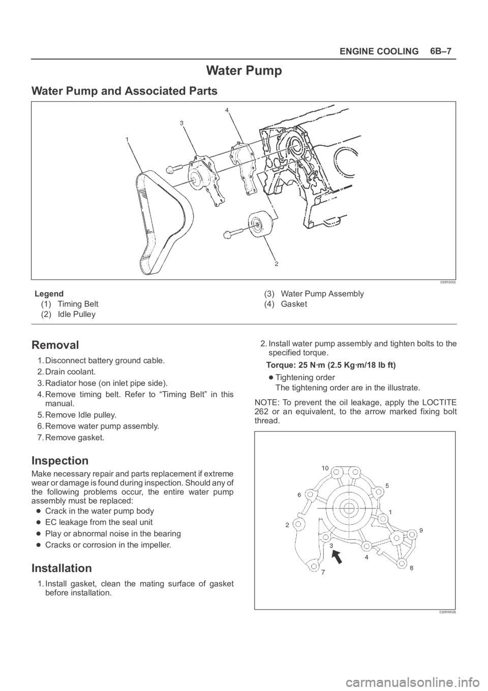
Water Pump and Associated Parts
030RS002
Legend
(1) Timing Belt
(2) Idle Pulley(3) Water Pump Assembly
(4) Gasket
Removal
1. Disconnect battery ground cable.
2. Drain coolant.
3. Radiator hose (on inlet pipe side).
4. Remove timing belt. Refer to “Timing Belt” in this
manual.
5. Remove Idle pulley.
6. Remove water pump assembly.
7. Remove gasket.
Inspection
Make necessary repair and parts replacement if extreme
wear or damage is found during inspection. Should any of
the following problems occur, the entire water pump
assembly must be replaced:
Crack in the water pump body
EC leakage from the seal unit
Play or abnormal noise in the bearing
Cracks or corrosion in the impeller.
Installation
1. Install gasket, clean the mating surface of gasket
before installation.2. Install water pump assembly and tighten bolts to the
specified torque.
Torque: 25 Nꞏm (2.5 Kgꞏm/18 lb ft)
Tightening order
The tightening order are in the illustrate.
NOTE: To prevent the oil leakage, apply the LOCTITE
262 or an equivalent, to the arrow marked fixing bolt
thread.
030RW008