1998 OPEL FRONTERA battery replacement
[x] Cancel search: battery replacementPage 2067 of 6000
6E–174
4JX1–TC ENGINE DRIVEABILITY AND EMISSIONS
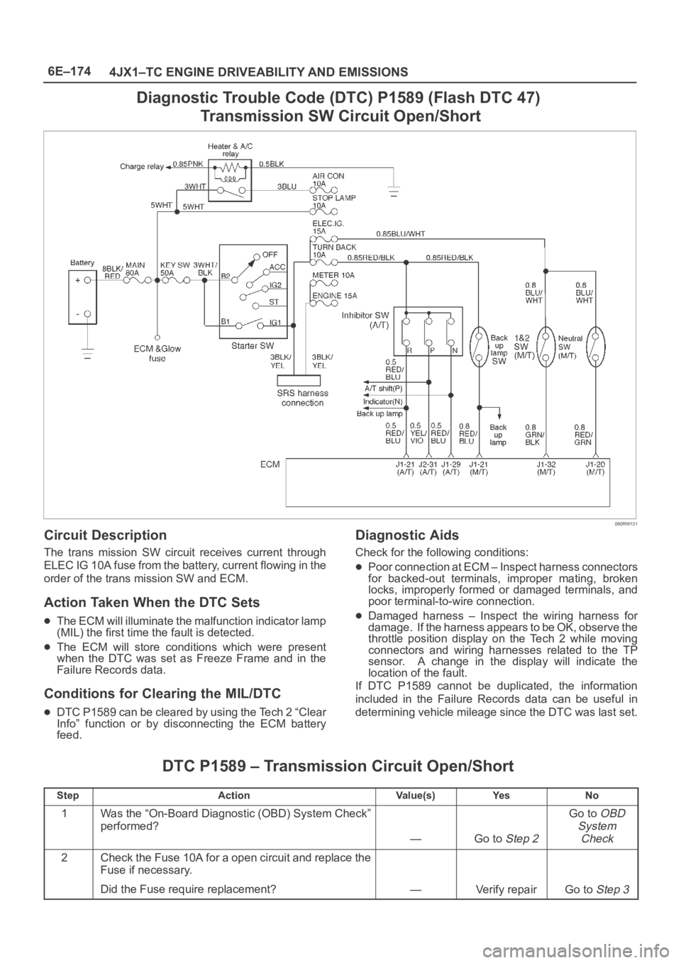
Diagnostic Trouble Code (DTC) P1589 (Flash DTC 47)
Transmission SW Circuit Open/Short
060RW131
Circuit Description
The trans mission SW circuit receives current through
ELEC IG 10A fuse from the battery, current flowing in the
order of the trans mission SW and ECM.
Action Taken When the DTC Sets
The ECM will illuminate the malfunction indicator lamp
(MIL) the first time the fault is detected.
The ECM will store conditions which were present
when the DTC was set as Freeze Frame and in the
Failure Records data.
Conditions for Clearing the MIL/DTC
DTC P1589 can be cleared by using the Tech 2 “Clear
Info” function or by disconnecting the ECM battery
feed.
Diagnostic Aids
Check for the following conditions:
Poor connection at ECM – Inspect harness connectors
for backed-out terminals, improper mating, broken
locks, improperly formed or damaged terminals, and
poor terminal-to-wire connection.
Damaged harness – Inspect the wiring harness for
damage. If the harness appears to be OK, observe the
throttle position display on the Tech 2 while moving
connectors and wiring harnesses related to the TP
sensor. A change in the display will indicate the
location of the fault.
If DTC P1589 cannot be duplicated, the information
included in the Failure Records data can be useful in
determining vehicle mileage since the DTC was last set.
DTC P1589 – Transmission Circuit Open/Short
StepActionVa l u e ( s )Ye sNo
1Was the “On-Board Diagnostic (OBD) System Check”
performed?
—Go to Step 2
Go to OBD
System
Check
2Check the Fuse 10A for a open circuit and replace the
Fuse if necessary.
Did the Fuse require replacement?
—Verify repairGo to Step 3
Page 2100 of 6000
6E–207 4JX1–TC ENGINE DRIVEABILITY AND EMISSIONS
damage, therefore, it is important to use care when
handling and testing electronic components.
NOTE: To prevent possible Electrostatic Discharge
damage, follow these guidelines:
Do not touch the control module connector pins or
soldered components on the control module circuit
board.
Do not open the replacement part package until the
part is ready to be installed.
Before removing the part from the package, ground
the package to a known good ground on the vehicle.
If the part has been handled while sliding across the
seat, or while sitting down from a standing position, or
while walking a distance, touch a known good ground
before installing the part.
NOTE: To prevent internal ECM damage, the ignition
must be in the “OFF” position in order to disconnect or
reconnect power to the ECM (for example: battery cable,
ECM pigtail, ECM fuse, jumper cables, etc.).
IMPORTANT:When replacing the production ECM
with a service ECM, it is important to transfer the
broadcast code and production ECM number to the
service ECM label. This will allow positive identification of
ECM parts throughout the service life of the vehicle. Do
not record this information on the metal ECM cover.
IMPORTANT:The ignition should always be in the
“OFF” position in order to install or remove the ECM
connectors.
Service of the ECM should normally consist of either re-
placement of the ECM. If the diagnostic procedures call
for the ECM to be replaced, the ECM should be checked
first to ensure it is the correct part. If it is, remove the
faulty ECM and install the new service ECM.
DTC P0601 indicates the check sum error.
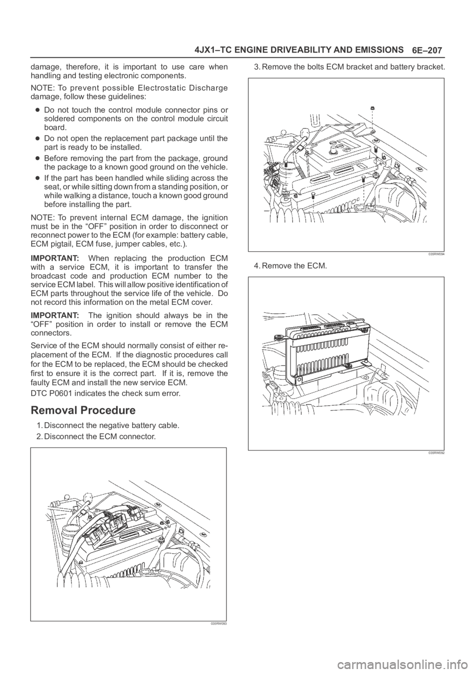
Removal Procedure
1. Disconnect the negative battery cable.
2. Disconnect the ECM connector.
035RW093
3. Remove the bolts ECM bracket and battery bracket.
035RW094
4. Remove the ECM.
035RW092
Page 2105 of 6000
6E–212
4JX1–TC ENGINE DRIVEABILITY AND EMISSIONS
Installation Procedure
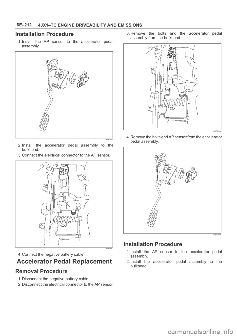
1. Install the AP sensor to the accelerator pedal
assembly.
035RW066
2. Install the accelerator pedal assembly to the
bulkhead.
3. Connect the electrical connector to the AP sensor.
035RW060
4. Connect the negative battery cable.
Accelerator Pedal Replacement
Removal Procedure
1. Disconnect the negative battery cable.
2. Disconnect the electrical connector to the AP sensor.3.Remove the bolts and the accelerator pedal
assembly from the bulkhead.
035RW060
4. Remove the bolts and AP sensor from the accelerator
pedal assembly.
035RW066
Installation Procedure
1. Install the AP sensor to the accelerator pedal
assembly.
2. Install the accelerator pedal assembly to the
bulkhead.
Page 2113 of 6000
6E–220
4JX1–TC ENGINE DRIVEABILITY AND EMISSIONS
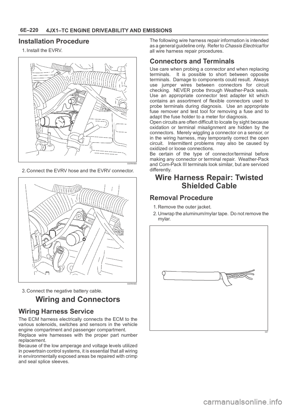
Installation Procedure
1. Install the EVRV.
035RW064
2. Connect the EVRV hose and the EVRV connector.
035RW065
3. Connect the negative battery cable.
Wiring and Connectors
Wiring Harness Service
The ECM harness electrically connects the ECM to the
various solenoids, switches and sensors in the vehicle
engine compartment and passenger compartment.
Replace wire harnesses with the proper part number
replacement.
Because of the low amperage and voltage levels utilized
in powertrain control systems, it is essential that all wiring
in environmentally exposed areas be repaired with crimp
and seal splice sleeves.The following wire harness repair information is intended
as a general guideline only. Refer to
Chassis Electrical f o r
all wire harness repair procedures.
Connectors and Terminals
Use care when probing a connector and when replacing
terminals. It is possible to short between opposite
terminals. Damage to components could result. Always
use jumper wires between connectors for circuit
checking. NEVER probe through Weather-Pack seals.
Use an appropriate connector test adapter kit which
contains an assortment of flexible connectors used to
probe terminals during diagnosis. Use an appropriate
fuse remover and test tool for removing a fuse and to
adapt the fuse holder to a meter for diagnosis.
Open circuits are often difficult to locate by sight because
oxidation or terminal misalignment are hidden by the
connectors. Merely wiggling a connector on a sensor, or
in the wiring harness, may temporarily correct the open
circuit. Intermittent problems may also be caused by
oxidized or loose connections.
Be certain of the type of connector/terminal before
making any connector or terminal repair. Weather-Pack
and Com-Pack III terminals look similar, but are serviced
differently.
Wire Harness Repair: Twisted
Shielded Cable
Removal Procedure
1. Remove the outer jacket.
2. Unwrap the aluminum/mylar tape. Do not remove the
mylar.
047
Page 2120 of 6000
6E–227 4JX1–TC ENGINE DRIVEABILITY AND EMISSIONS
QOS
Diagnostics
– Malfunction Indicator Lamp (Service Engine
Soon lamp)
– Data Link Connector (DLC)
– Data Output
ECM Service Precautions
The ECM is designed to withstand normal current draws
associated with vehicle operation. Avoid overloading any
circuit. When testing for opens and shorts, do not ground
or apply voltage to any of the ECM’s circuits unless
instructed to do so. These circuits should only be tested
using digital voltmeter. The ECM should remain
connected to the ECM or to a recommended breakout
box.
Intake Throttle Position (ITP) Sensor
ITP sensor is a potentiometer type and installed to the
intake throttle valve body. A voltage of 5V is applied
constantly from ECM to ITP sensor thereby to determine
by change in voltage the opening of the intake throttle
valve during warming up.
Transmission Range Switch
IMPORTANT:The vehicle should not be driven with the
transmission range switch disconnected; idle quality will
be affected.
The four inputs from the transmission range switch
indicate to the ECM which position is selected by the
transmission selector lever.
For more information on the transmission on the
transmission range switch, refer to
Automatic
Tr a n s m i s s i o n
.
Accelerator Position Sensor (AP)
AP sensor is a potentiometer type and installed to
accelerator pedal bracket. A voltage of 5V constantly
applied from ECM to the sensor thereby to determine the
accelerator pedaling angle by change in voltage. Further,
this sensor is provided with an accelerator switch, which
is set off only when the accelerator pedal is stepped on.
Aftermarket Electrical and Vacuum
Equipment
Aftermarket (add-on) electrical and vacuum equipment is
defined as any equipment which connects to the vehicle’s
electrical or vacuum systems that is installed on a vehicle
after it leaves the factory. No allowances have been
made in the vehicle design for this type of equipment.
NOTE: No add-on vacuum equipment should be added
to this vehicle.
NOTE: Add-on electrical equipment must only be
connected to the vehicle’s electrical system at the battery
(power and ground).
Add-on electrical equipment, even when installed to
these guidelines, may still cause the powertrain system to
malfunction. This may also include equipment not
connected to the vehicle electrical system such asportable telephones and radios. Therefore, the first step
in diagnosing any powertrain problem is to eliminate all
aftermarket electrical equipment from the vehicle. After
this is done, if the problem still exists, it may be diagnosed
in the normal manner.
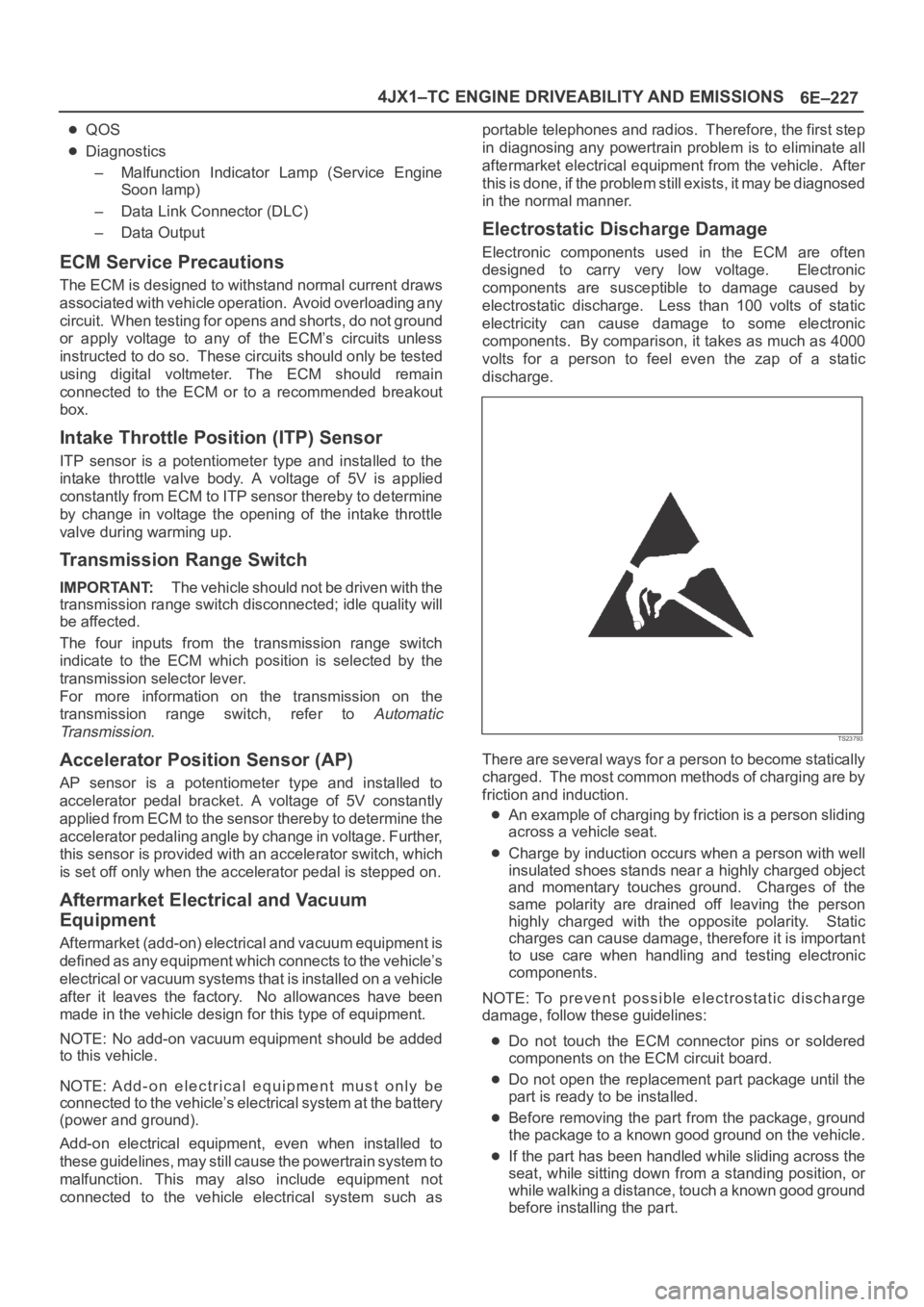
Electrostatic Discharge Damage
Electronic components used in the ECM are often
designed to carry very low voltage. Electronic
components are susceptible to damage caused by
electrostatic discharge. Less than 100 volts of static
electricity can cause damage to some electronic
components. By comparison, it takes as much as 4000
volts for a person to feel even the zap of a static
discharge.
TS23793
There are several ways for a person to become statically
charged. The most common methods of charging are by
friction and induction.
An example of charging by friction is a person sliding
across a vehicle seat.
Charge by induction occurs when a person with well
insulated shoes stands near a highly charged object
and momentary touches ground. Charges of the
same polarity are drained off leaving the person
highly charged with the opposite polarity. Static
charges can cause damage, therefore it is important
to use care when handling and testing electronic
components.
NOTE: To prevent possible electrostatic discharge
damage, follow these guidelines:
Do not touch the ECM connector pins or soldered
components on the ECM circuit board.
Do not open the replacement part package until the
part is ready to be installed.
Before removing the part from the package, ground
the package to a known good ground on the vehicle.
If the part has been handled while sliding across the
seat, while sitting down from a standing position, or
while walking a distance, touch a known good ground
before installing the part.
Page 2137 of 6000
6G – 6 ENGINE LUBRICATION
OIL COOLER ASSEMBLY
REMOVAL
1. Disconnect battery ground cable.
2. Drain engine coolant.
3. Remove front exhaust pipe.
4. Remove heat protector.
5. Remove exhaust valve assembly.
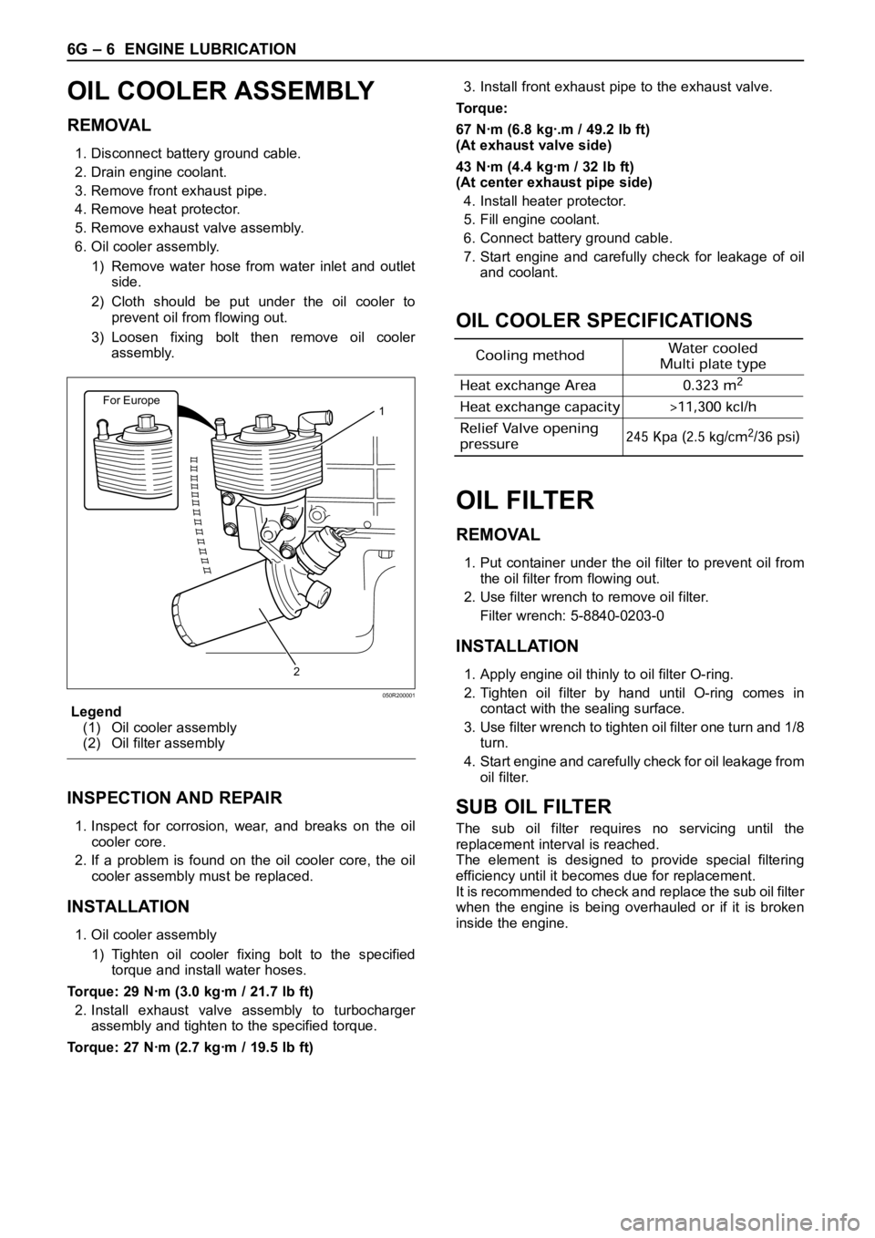
6. Oil cooler assembly.
1) Remove water hose from water inlet and outlet
side.
2) Cloth should be put under the oil cooler to
prevent oil from flowing out.
3) Loosen fixing bolt then remove oil cooler
assembly.
Legend
(1) Oil cooler assembly
(2) Oil filter assembly
INSPECTION AND REPAIR
1. Inspect for corrosion, wear, and breaks on the oil
cooler core.
2. If a problem is found on the oil cooler core, the oil
cooler assembly must be replaced.
INSTALLATION
1. Oil cooler assembly
1) Tighten oil cooler fixing bolt to the specified
torque and install water hoses.
Torque: 29 Nꞏm (3.0 kgꞏm / 21.7 lb ft)
2. Install exhaust valve assembly to turbocharger
assembly and tighten to the specified torque.
Torque: 27 Nꞏm (2.7 kgꞏm / 19.5 lb ft)3. Install front exhaust pipe to the exhaust valve.
Torque:
67 Nꞏm (6.8 kgꞏ.m / 49.2 lb ft)
(At exhaust valve side)
43 Nꞏm (4.4 kgꞏm / 32 lb ft)
(At center exhaust pipe side)
4. Install heater protector.
5. Fill engine coolant.
6. Connect battery ground cable.
7. Start engine and carefully check for leakage of oil
and coolant.
OIL COOLER SPECIFICATIONS
OIL FILTER
REMOVAL
1. Put container under the oil filter to prevent oil from
the oil filter from flowing out.
2. Use filter wrench to remove oil filter.
Filter wrench: 5-8840-0203-0
INSTALLATION
1. Apply engine oil thinly to oil filter O-ring.
2. Tighten oil filter by hand until O-ring comes in
contact with the sealing surface.
3. Use filter wrench to tighten oil filter one turn and 1/8
turn.
4. Start engine and carefully check for oil leakage from
oil filter.
SUB OIL FILTER
The sub oil filter requires no servicing until the
replacement interval is reached.
The element is designed to provide special filtering
efficiency until it becomes due for replacement.
It is recommended to check and replace the sub oil filter
when the engine is being overhauled or if it is broken
inside the engine.
For Europe1
2
050R200001
Page 2288 of 6000
TRANSMISSION CONTROL SYSTEM (4L30–E)7A1–43
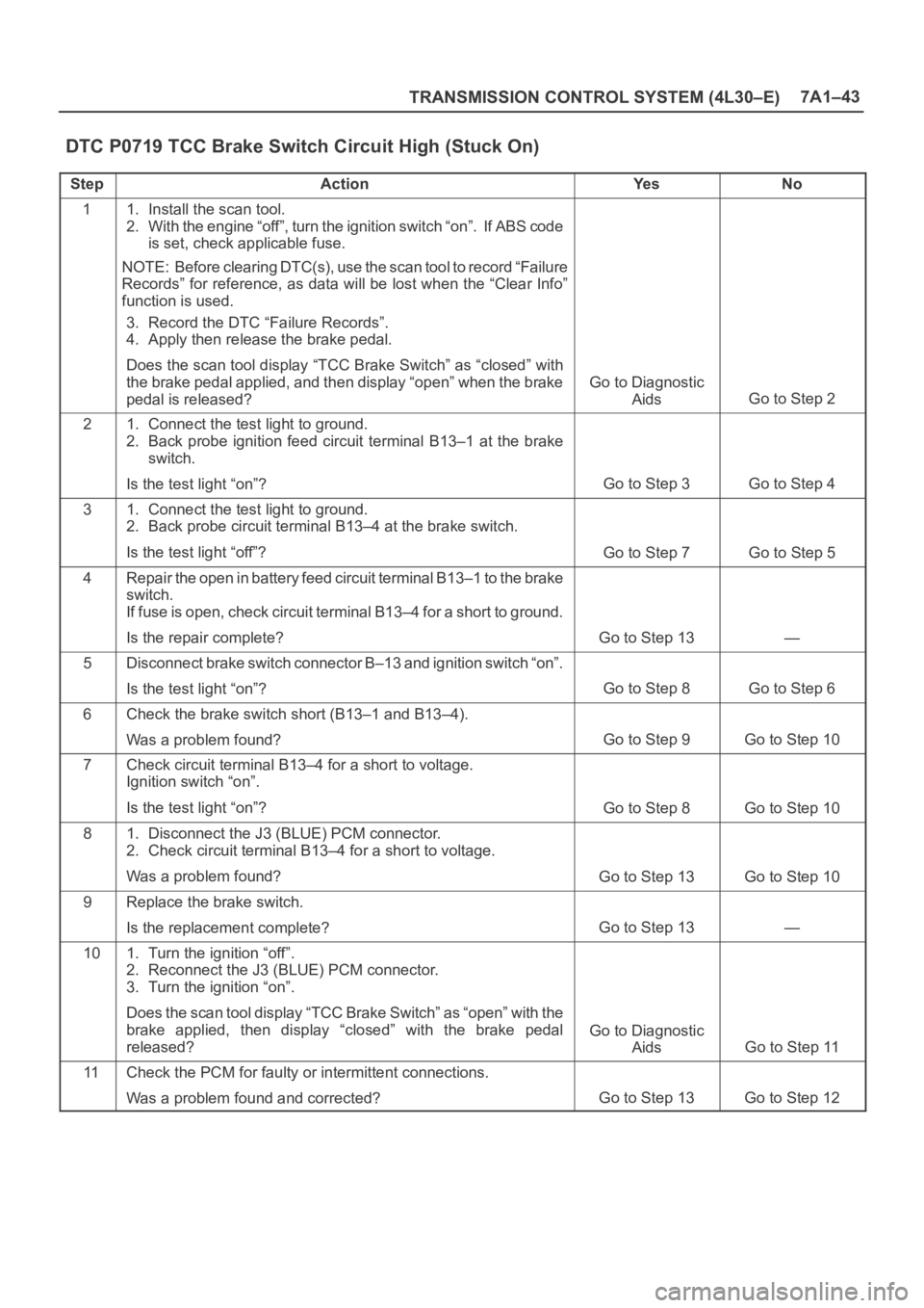
DTC P0719 TCC Brake Switch Circuit High (Stuck On)
StepActionYe sNo
11. Install the scan tool.
2. With the engine “off”, turn the ignition switch “on”. If ABS code
is set, check applicable fuse.
NOTE: Before clearing DTC(s), use the scan tool to record “Failure
Records” for reference, as data will be lost when the “Clear Info”
function is used.
3. Record the DTC “Failure Records”.
4. Apply then release the brake pedal.
Does the scan tool display “TCC Brake Switch” as “closed” with
the brake pedal applied, and then display “open” when the brake
pedal is released?
Go to Diagnostic
Aids
Go to Step 2
21. Connect the test light to ground.
2. Back probe ignition feed circuit terminal B13–1 at the brake
switch.
Is the test light “on”?
Go to Step 3Go to Step 4
31. Connect the test light to ground.
2. Back probe circuit terminal B13–4 at the brake switch.
Is the test light “off”?
Go to Step 7Go to Step 5
4Repair the open in battery feed circuit terminal B13–1 to the brake
switch.
If fuse is open, check circuit terminal B13–4 for a short to ground.
Is the repair complete?
Go to Step 13—
5Disconnect brake switch connector B–13 and ignition switch “on”.
Is the test light “on”?
Go to Step 8Go to Step 6
6Check the brake switch short (B13–1 and B13–4).
Was a problem found?
Go to Step 9Go to Step 10
7Check circuit terminal B13–4 for a short to voltage.
Ignition switch “on”.
Is the test light “on”?
Go to Step 8Go to Step 10
81. Disconnect the J3 (BLUE) PCM connector.
2. Check circuit terminal B13–4 for a short to voltage.
Was a problem found?
Go to Step 13Go to Step 10
9Replace the brake switch.
Is the replacement complete?
Go to Step 13—
101. Turn the ignition “off”.
2. Reconnect the J3 (BLUE) PCM connector.
3. Turn the ignition “on”.
Does the scan tool display “TCC Brake Switch” as “open” with the
brake applied, then display “closed” with the brake pedal
released?
Go to Diagnostic
Aids
Go to Step 11
11Check the PCM for faulty or intermittent connections.
Was a problem found and corrected?
Go to Step 13Go to Step 12
Page 2571 of 6000
8B–2WIPER/WASHER SYSTEM
Service Precaution
WARNING: IF SO EQUIPPED WITH A
SUPPLEMENTAL RESTRAINT SYSTEM (SRS),
REFER TO THE SRS COMPONENT AND WIRING
LOCATION VIEW IN ORDER TO DETERMINE
WHETHER YOU ARE PERFORMING SERVICE ON OR
NEAR THE SRS COMPONENTS OR THE SRS
WIRING. WHEN YOU ARE PERFORMING SERVICE
ON OR NEAR THE SRS COMPONENTS OR THE SRS
WIRING, REFER TO THE SRS SERVICE
INFORMATION. FAILURE TO FOLLOW WARNINGS
COULD RESULT IN POSSIBLE AIR BAG
DEPLOYMENT, PERSONAL INJURY, OR
OTHERWISE UNNEEDED SRS SYSTEM REPAIRS.CAUTION: Always use the correct fastener in the
proper location. When you replace a fastener, use
ONLY the exact part number for that application.
ISUZU will call out those fasteners that require a
replacement after removal. ISUZU will also call out
the fasteners that require thread lockers or thread
sealant. UNLESS OTHERWISE SPECIFIED, do not
use supplemental coatings (Paints, greases, or other
corrosion inhibitors) on threaded fasteners or
fastener joint interfaces. Generally, such coatings
adversely affect the fastener torque and the joint
clamping force, and may damage the fastener. When
you install fasteners, use the correct tightening
sequence and specifications. Following these
instructions can help you avoid damage to parts and
systems.
Windshield Wiper/Washer System
General Description
The circuit consists of the starter switch, windshield wiper
& washer switch, windshield wiper motor, windshield
washer motor and windshield intermittent relay.When the wiper & washer switch is turned on with the
starter switch on, the battery voltage is applied to the
wiper motor to activate the wiper.
The washer motor squirts glass cleaning fluid while the
washer switch is being pushed. The intermittent relay is
used to control motion of the wiper.
Windshield Wiper And Washer Switch
Removal and Installation
Refer to the Lighting Switch (Combination Switch) in
Lighting System section.
Windshield Wiper Motor
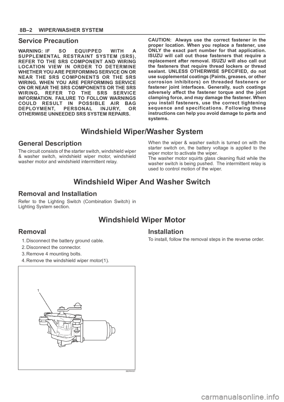
Removal
1. Disconnect the battery ground cable.
2. Disconnect the connector.
3. Remove 4 mounting bolts.
4. Remove the windshield wiper motor(1).
880RW007
Installation
To install, follow the removal steps in the reverse order.