1998 OPEL FRONTERA fuel pressure
[x] Cancel search: fuel pressurePage 5610 of 6000
6E–181 4JX1–TC ENGINE DRIVEABILITY AND EMISSIONS
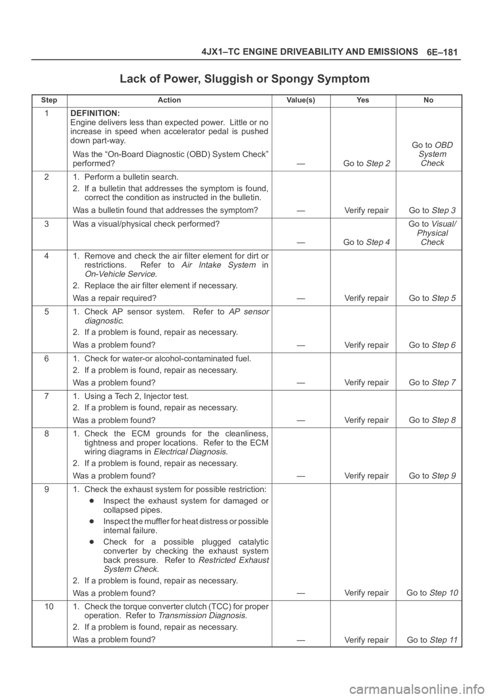
Lack of Power, Sluggish or Spongy Symptom
StepActionVa l u e ( s )Ye sNo
1DEFINITION:
Engine delivers less than expected power. Little or no
increase in speed when accelerator pedal is pushed
down part-way.
Was the “On-Board Diagnostic (OBD) System Check”
performed?
—Go to Step 2
Go to OBD
System
Check
21. Perform a bulletin search.
2. If a bulletin that addresses the symptom is found,
correct the condition as instructed in the bulletin.
Was a bulletin found that addresses the symptom?
—Verify repairGo to Step 3
3Was a visual/physical check performed?
—Go to Step 4
Go to Visual/
Physical
Check
41. Remove and check the air filter element for dirt or
restrictions. Refer to
Air Intake System in
On-Vehicle Service.
2. Replace the air filter element if necessary.
Was a repair required?
—Verify repairGo to Step 5
51. Check AP sensor system. Refer to AP sensor
diagnostic
.
2. If a problem is found, repair as necessary.
Was a problem found?
—Verify repairGo to Step 6
61. Check for water-or alcohol-contaminated fuel.
2. If a problem is found, repair as necessary.
Was a problem found?
—Verify repairGo to Step 7
71. Using a Tech 2, Injector test.
2. If a problem is found, repair as necessary.
Was a problem found?
—Verify repairGo to Step 8
81. Check the ECM grounds for the cleanliness,
tightness and proper locations. Refer to the ECM
wiring diagrams in
Electrical Diagnosis.
2. If a problem is found, repair as necessary.
Was a problem found?
—Verify repairGo to Step 9
91. Check the exhaust system for possible restriction:
Inspect the exhaust system for damaged or
collapsed pipes.
Inspect the muffler for heat distress or possible
internal failure.
Check for a possible plugged catalytic
converter by checking the exhaust system
back pressure. Refer to
Restricted Exhaust
System Check
.
2. If a problem is found, repair as necessary.
Was a problem found?
—Verify repairGo to Step 10
101. Check the torque converter clutch (TCC) for proper
operation. Refer to
Transmission Diagnosis.
2. If a problem is found, repair as necessary.
Was a problem found?
—Verify repairGo to Step 11
Page 5614 of 6000
6E–185 4JX1–TC ENGINE DRIVEABILITY AND EMISSIONS
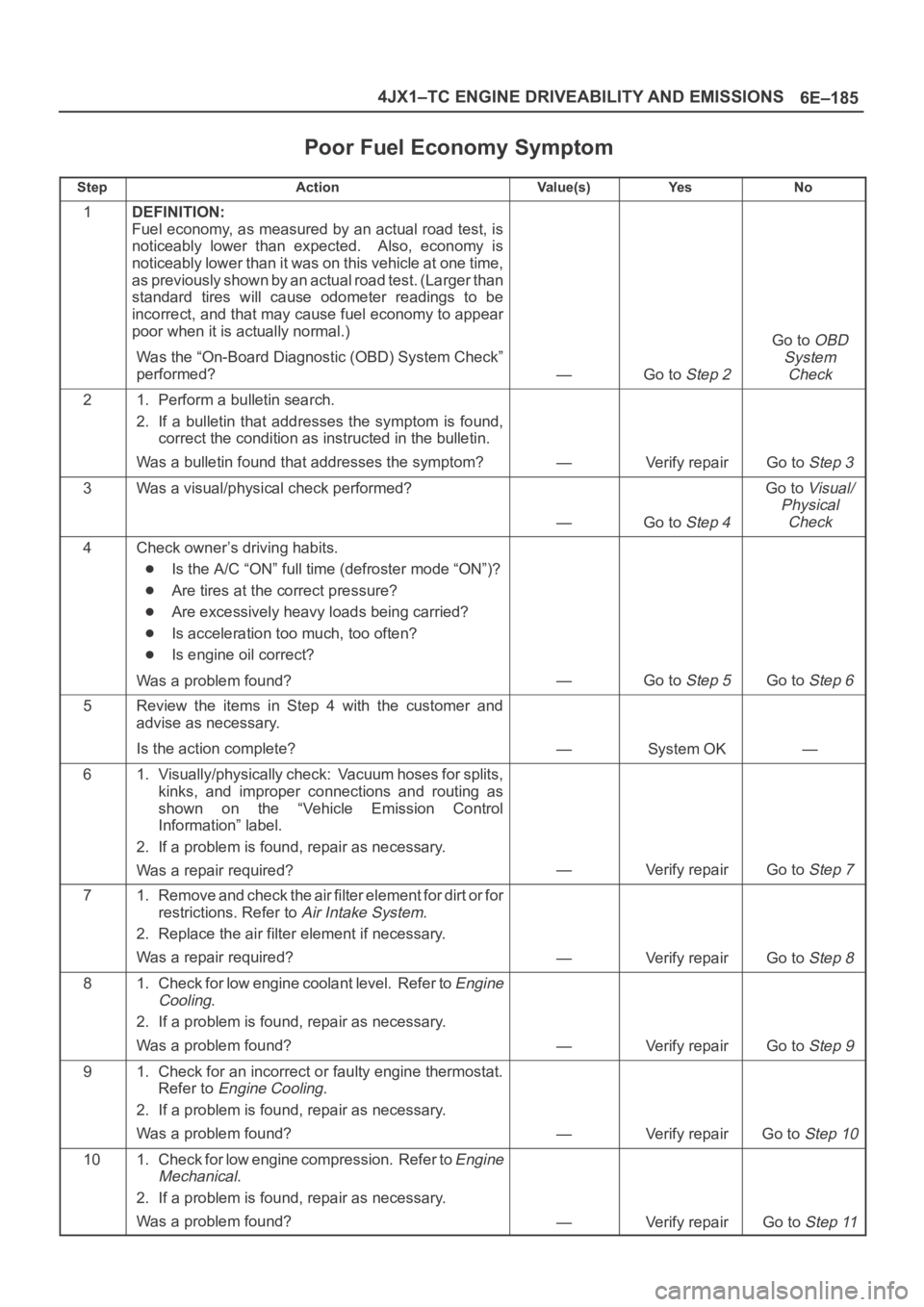
Poor Fuel Economy Symptom
StepActionVa l u e ( s )Ye sNo
1DEFINITION:
Fuel economy, as measured by an actual road test, is
noticeably lower than expected. Also, economy is
noticeably lower than it was on this vehicle at one time,
as previously shown by an actual road test. (Larger than
standard tires will cause odometer readings to be
incorrect, and that may cause fuel economy to appear
poor when it is actually normal.)
Was the “On-Board Diagnostic (OBD) System Check”
performed?
—Go to Step 2
Go to OBD
System
Check
21. Perform a bulletin search.
2. If a bulletin that addresses the symptom is found,
correct the condition as instructed in the bulletin.
Was a bulletin found that addresses the symptom?
—Verify repairGo to Step 3
3Was a visual/physical check performed?
—Go to Step 4
Go to Visual/
Physical
Check
4Check owner’s driving habits.
Is the A/C “ON” full time (defroster mode “ON”)?
Are tires at the correct pressure?
Are excessively heavy loads being carried?
Is acceleration too much, too often?
Is engine oil correct?
Was a problem found?
—Go to Step 5Go to Step 6
5Review the items in Step 4 with the customer and
advise as necessary.
Is the action complete?
—System OK—
61. Visually/physically check: Vacuum hoses for splits,
kinks, and improper connections and routing as
shown on the “Vehicle Emission Control
Information” label.
2. If a problem is found, repair as necessary.
Was a repair required?
—Verify repairGo to Step 7
71. Remove and check the air filter element for dirt or for
restrictions. Refer to
Air Intake System.
2. Replace the air filter element if necessary.
Was a repair required?
—Verify repairGo to Step 8
81. Check for low engine coolant level. Refer to Engine
Cooling
.
2. If a problem is found, repair as necessary.
Was a problem found?
—Verify repairGo to Step 9
91. Check for an incorrect or faulty engine thermostat.
Refer to
Engine Cooling.
2. If a problem is found, repair as necessary.
Was a problem found?
—Verify repairGo to Step 10
101. Check for low engine compression. Refer to Engine
Mechanical
.
2. If a problem is found, repair as necessary.
Was a problem found?
—Verify repairGo to Step 11
Page 5615 of 6000
6E–186
4JX1–TC ENGINE DRIVEABILITY AND EMISSIONS
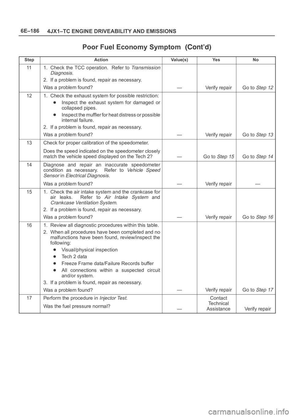
Poor Fuel Economy Symptom
StepNo Ye s Va l u e ( s ) Action
111. Check the TCC operation. Refer to Transmission
Diagnosis
.
2. If a problem is found, repair as necessary.
Was a problem found?
—Verify repairGo to Step 12
121. Check the exhaust system for possible restriction:
Inspect the exhaust system for damaged or
collapsed pipes.
Inspect the muffler for heat distress or possible
internal failure.
2. If a problem is found, repair as necessary.
Was a problem found?
—Verify repairGo to Step 13
13Check for proper calibration of the speedometer.
Does the speed indicated on the speedometer closely
match the vehicle speed displayed on the Tech 2?
—Go to Step 15Go to Step 14
14Diagnose and repair an inaccurate speedometer
condition as necessary. Refer to
Vehicle Speed
Sensor
in Electrical Diagnosis.
Was a problem found?
—Verify repair—
151. Check the air intake system and the crankcase for
air leaks. Refer to
Air Intake System and
Crankcase Ventilation System.
2. If a problem is found, repair as necessary.
Was a problem found?
—Verify repairGo to Step 16
161. Review all diagnostic procedures within this table.
2. When all procedures have been completed and no
malfunctions have been found, review/inspect the
following:
Visual/physical inspection
Te c h 2 d a t a
Freeze Frame data/Failure Records buffer
All connections within a suspected circuit
and/or system.
3. If a problem is found, repair as necessary.
Was a problem found?
—Verify repairGo to Step 17
17Perform the procedure in Injector Test.
Was the fuel pressure normal?
—
Contact
Te c h n i c a l
Assistance
Verify repair
Page 5642 of 6000
6E–213 4JX1–TC ENGINE DRIVEABILITY AND EMISSIONS
3. Connect the electrical connector to the AP sensor.
035RW060
4. Connect the negative battery cable.
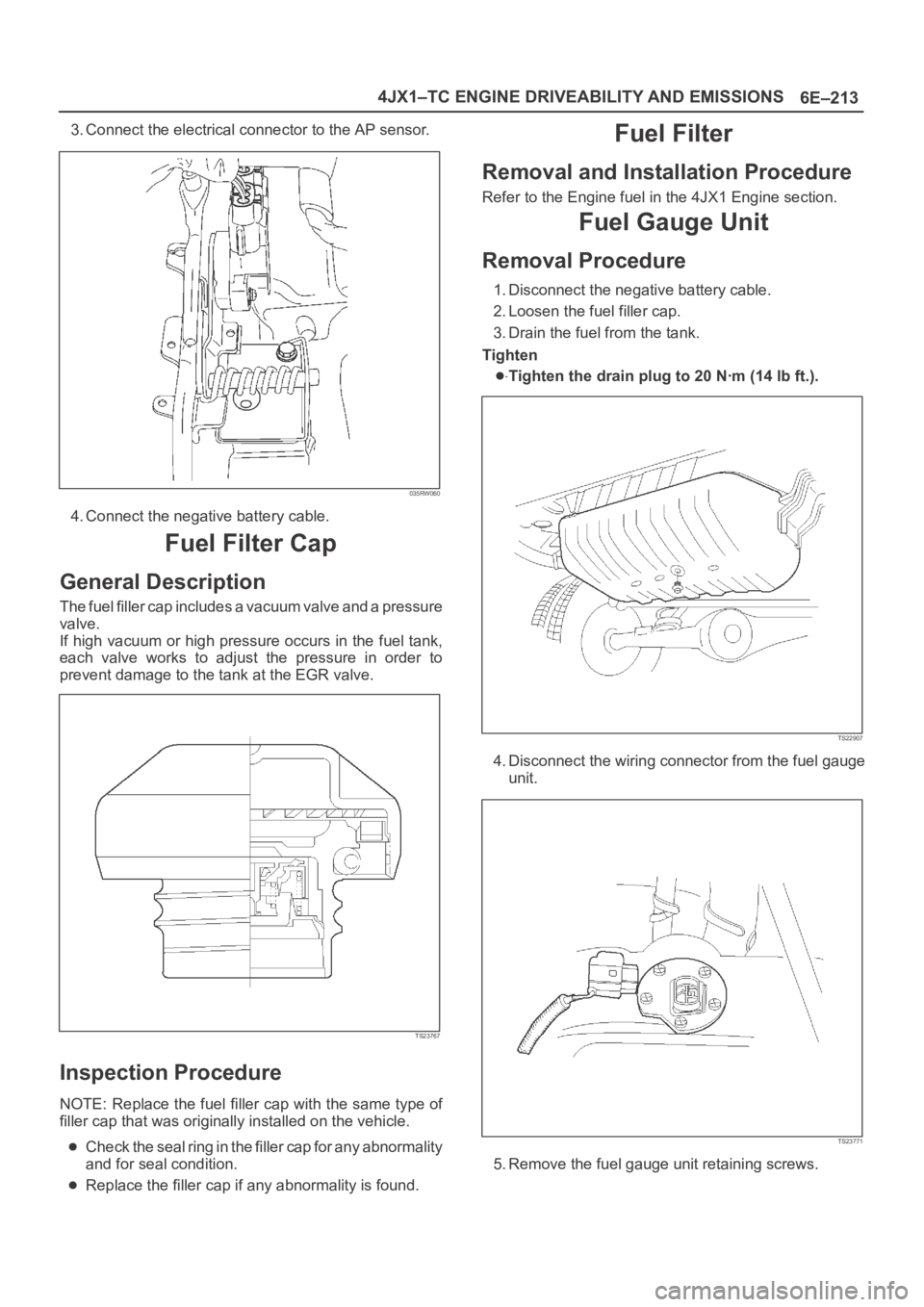
Fuel Filter Cap
General Description
The fuel filler cap includes a vacuum valve and a pressure
valve.
If high vacuum or high pressure occurs in the fuel tank,
each valve works to adjust the pressure in order to
prevent damage to the tank at the EGR valve.
TS23767
Inspection Procedure
NOTE: Replace the fuel filler cap with the same type of
filler cap that was originally installed on the vehicle.
Check the seal ring in the filler cap for any abnormality
and for seal condition.
Replace the filler cap if any abnormality is found.
Fuel Filter
Removal and Installation Procedure
Refer to the Engine fuel in the 4JX1 Engine section.
Fuel Gauge Unit
Removal Procedure
1. Disconnect the negative battery cable.
2. Loosen the fuel filler cap.
3. Drain the fuel from the tank.
Tighten
Tighten the drain plug to 20 Nꞏm (14 lb ft.).
TS22907
4. Disconnect the wiring connector from the fuel gauge
unit.
TS23771
5. Remove the fuel gauge unit retaining screws.
Page 5643 of 6000
6E–214
4JX1–TC ENGINE DRIVEABILITY AND EMISSIONS
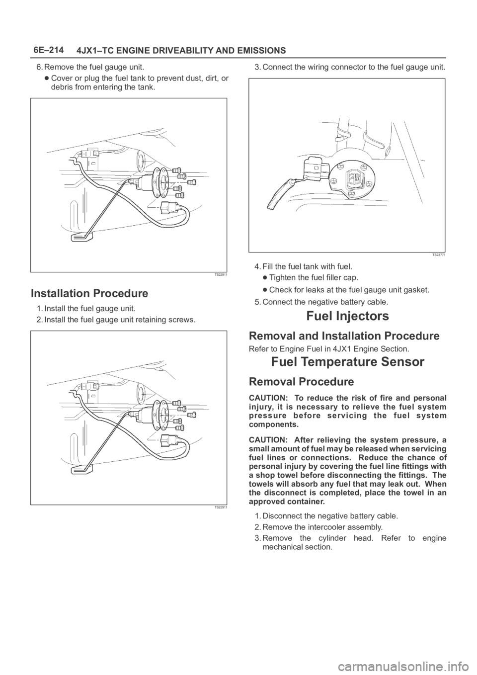
6. Remove the fuel gauge unit.
Cover or plug the fuel tank to prevent dust, dirt, or
debris from entering the tank.
TS22911
Installation Procedure
1. Install the fuel gauge unit.
2. Install the fuel gauge unit retaining screws.
TS22911
3. Connect the wiring connector to the fuel gauge unit.
TS23771
4. Fill the fuel tank with fuel.
Tighten the fuel filler cap.
Check for leaks at the fuel gauge unit gasket.
5. Connect the negative battery cable.
Fuel Injectors
Removal and Installation Procedure
Refer to Engine Fuel in 4JX1 Engine Section.
Fuel Temperature Sensor
Removal Procedure
CAUTION: To reduce the risk of fire and personal
injury, it is necessary to relieve the fuel system
pressure before servicing the fuel system
components.
CAUTION: After relieving the system pressure, a
small amount of fuel may be released when servicing
fuel lines or connections. Reduce the chance of
personal injury by covering the fuel line fittings with
a shop towel before disconnecting the fittings. The
towels will absorb any fuel that may leak out. When
the disconnect is completed, place the towel in an
approved container.
1. Disconnect the negative battery cable.
2. Remove the intercooler assembly.
3. Remove the cylinder head. Refer to engine
mechanical section.
Page 5644 of 6000
6E–215 4JX1–TC ENGINE DRIVEABILITY AND EMISSIONS
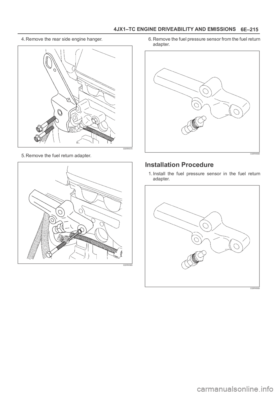
4. Remove the rear side engine hanger.
035RW070
5. Remove the fuel return adapter.
035RW069
6. Remove the fuel pressure sensor from the fuel return
adapter.
035RW068
Installation Procedure
1. Install the fuel pressure sensor in the fuel return
adapter.
035RW068
Page 5645 of 6000
6E–216
4JX1–TC ENGINE DRIVEABILITY AND EMISSIONS
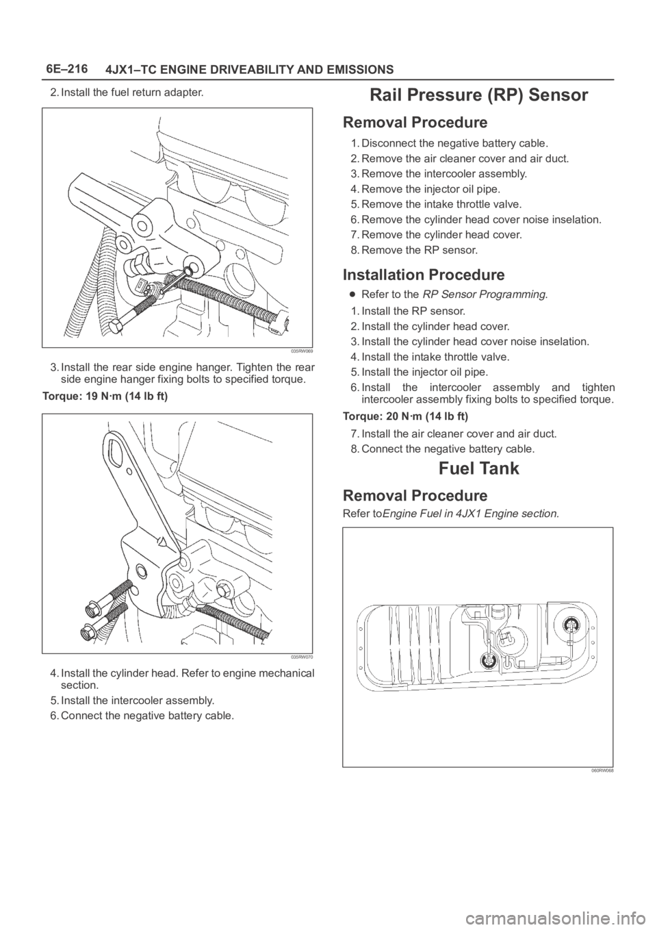
2. Install the fuel return adapter.
035RW069
3. Install the rear side engine hanger. Tighten the rear
side engine hanger fixing bolts to specified torque.
Torque: 19 Nꞏm (14 lb ft)
035RW070
4. Install the cylinder head. Refer to engine mechanical
section.
5. Install the intercooler assembly.
6. Connect the negative battery cable.
Rail Pressure (RP) Sensor
Removal Procedure
1. Disconnect the negative battery cable.
2. Remove the air cleaner cover and air duct.
3. Remove the intercooler assembly.
4. Remove the injector oil pipe.
5. Remove the intake throttle valve.
6. Remove the cylinder head cover noise inselation.
7. Remove the cylinder head cover.
8. Remove the RP sensor.
Installation Procedure
Refer to the RP Sensor Programming.
1. Install the RP sensor.
2. Install the cylinder head cover.
3. Install the cylinder head cover noise inselation.
4. Install the intake throttle valve.
5. Install the injector oil pipe.
6. Install the intercooler assembly and tighten
intercooler assembly fixing bolts to specified torque.
Torque: 20 Nꞏm (14 lb ft)
7. Install the air cleaner cover and air duct.
8. Connect the negative battery cable.
Fuel Tank
Removal Procedure
Refer toEngine Fuel in 4JX1 Engine section.
060RW068
Page 5655 of 6000
6E–226
4JX1–TC ENGINE DRIVEABILITY AND EMISSIONS
0018
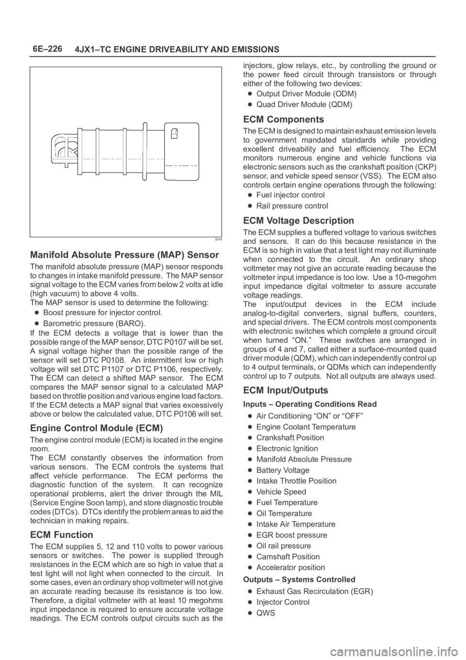
Manifold Absolute Pressure (MAP) Sensor
The manifold absolute pressure (MAP) sensor responds
to changes in intake manifold pressure. The MAP sensor
signal voltage to the ECM varies from below 2 volts at idle
(high vacuum) to above 4 volts.
The MAP sensor is used to determine the following:
Boost pressure for injector control.
Barometric pressure (BARO).
If the ECM detects a voltage that is lower than the
possible range of the MAP sensor, DTC P0107 will be set.
A signal voltage higher than the possible range of the
sensor will set DTC P0108. An intermittent low or high
voltage will set DTC P1107 or DTC P1106, respectively.
The ECM can detect a shifted MAP sensor. The ECM
compares the MAP sensor signal to a calculated MAP
based on throttle position and various engine load factors.
If the ECM detects a MAP signal that varies excessively
above or below the calculated value, DTC P0106 will set.
Engine Control Module (ECM)
The engine control module (ECM) is located in the engine
room.
The ECM constantly observes the information from
various sensors. The ECM controls the systems that
affect vehicle performance. The ECM performs the
diagnostic function of the system. It can recognize
operational problems, alert the driver through the MIL
(Service Engine Soon lamp), and store diagnostic trouble
codes (DTCs). DTCs identify the problem areas to aid the
technician in making repairs.
ECM Function
The ECM supplies 5, 12 and 110 volts to power various
sensors or switches. The power is supplied through
resistances in the ECM which are so high in value that a
test light will not light when connected to the circuit. In
some cases, even an ordinary shop voltmeter will not give
an accurate reading because its resistance is too low.
Therefore, a digital voltmeter with at least 10 megohms
input impedance is required to ensure accurate voltage
readings. The ECM controls output circuits such as theinjectors, glow relays, etc., by controlling the ground or
the power feed circuit through transistors or through
either of the following two devices:
Output Driver Module (ODM)
Quad Driver Module (QDM)
ECM Components
The ECM is designed to maintain exhaust emission levels
to government mandated standards while providing
excellent driveability and fuel efficiency. The ECM
monitors numerous engine and vehicle functions via
electronic sensors such as the crankshaft position (CKP)
sensor, and vehicle speed sensor (VSS). The ECM also
controls certain engine operations through the following:
Fuel injector control
Rail pressure control
ECM Voltage Description
The ECM supplies a buffered voltage to various switches
and sensors. It can do this because resistance in the
ECM is so high in value that a test light may not illuminate
when connected to the circuit. An ordinary shop
voltmeter may not give an accurate reading because the
voltmeter input impedance is too low. Use a 10-megohm
input impedance digital voltmeter to assure accurate
voltage readings.
The input/output devices in the ECM include
analog-to-digital converters, signal buffers, counters,
and special drivers. The ECM controls most components
with electronic switches which complete a ground circuit
when turned “ON.” These switches are arranged in
groups of 4 and 7, called either a surface-mounted quad
driver module (QDM), which can independently control up
to 4 output terminals, or QDMs which can independently
control up to 7 outputs. Not all outputs are always used.
ECM Input/Outputs
Inputs – Operating Conditions Read
Air Conditioning “ON” or “OFF”
Engine Coolant Temperature
Crankshaft Position
Electronic Ignition
Manifold Absolute Pressure
Battery Voltage
Intake Throttle Position
Vehicle Speed
Fuel Temperature
Oil Temperature
Intake Air Temperature
EGR boost pressure
Oil rail pressure
Camshaft Position
Accelerator position
Outputs – Systems Controlled
Exhaust Gas Recirculation (EGR)
Injector Control
QWS