Page 4570 of 6000
6A–74
ENGINE MECHANICAL
015RW002
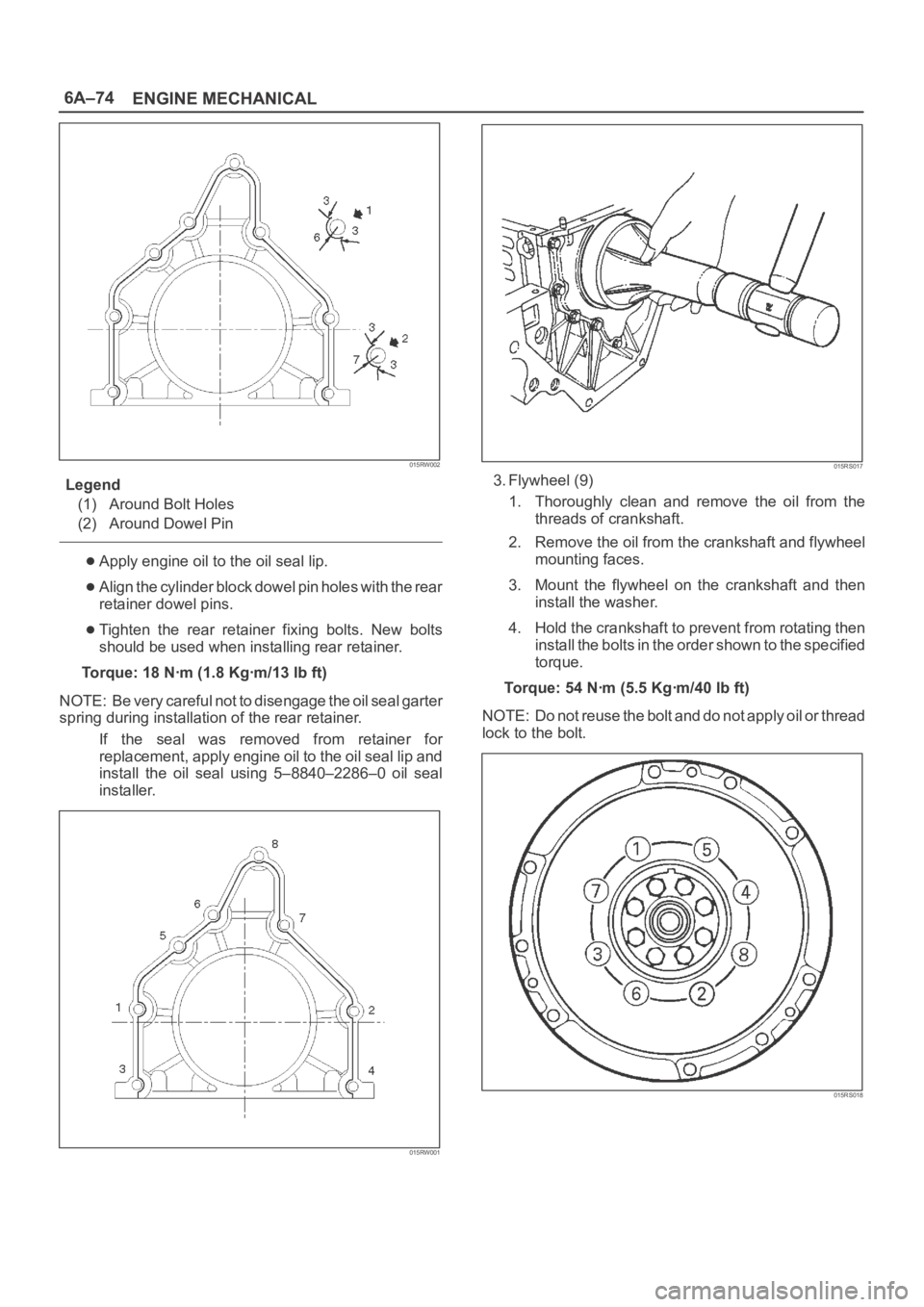
Legend
(1) Around Bolt Holes
(2) Around Dowel Pin
Apply engine oil to the oil seal lip.
Align the cylinder block dowel pin holes with the rear
retainer dowel pins.
Tighten the rear retainer fixing bolts. New bolts
should be used when installing rear retainer.
Torque: 18 Nꞏm (1.8 Kgꞏm/13 lb ft)
NOTE: Be very careful not to disengage the oil seal garter
spring during installation of the rear retainer.
If the seal was removed from retainer for
replacement, apply engine oil to the oil seal lip and
install the oil seal using 5–8840–2286–0 oil seal
installer.
015RW001
015RS017
3. Flywheel (9)
1. Thoroughly clean and remove the oil from the
threads of crankshaft.
2. Remove the oil from the crankshaft and flywheel
mounting faces.
3. Mount the flywheel on the crankshaft and then
install the washer.
4. Hold the crankshaft to prevent from rotating then
install the bolts in the order shown to the specified
torque.
Torque: 54 Nꞏm (5.5 Kgꞏm/40 lb ft)
NOTE: Do not reuse the bolt and do not apply oil or thread
lock to the bolt.
015RS018
Page 4581 of 6000
6A–85
ENGINE MECHANICAL
Cylinder Block
Cylinder Block and Associated Parts
012RW010
Legend
(1) Cylinder Head Assembly
(2) Cylinder Head Gasket
(3) Crankcase with Oil Pan
(4) Oil Pipe and O-Ring
(5) Oil Strainer and O-Ring
(6) Oil Pump Assembly
(7) Cylinder Block Side Bolts(8) Oil Gallery
(9) Piston and Connecting Rod Assembly
(10) Flywheel
(11) Rear Oil Seal Retainer Assembly
(12) Main Bearing Cap
(13) Crankshaft
(14) Cylinder Block
Disassembly
1. Remove cylinder head assembly.
2. Remove cylinder head gasket.
3. Remove crankcase with oil pan.
4. Remove oil pipe and O-ring.5. Remove oil strainer and O-ring.
6. Remove oil pump assembly.
7. Remove crankcase side bolts.
8. Remove oil gallery.
9. Remove piston and connecting rod assembly.
10. Remove flywheel.
Page 4584 of 6000
6A–88
ENGINE MECHANICAL
015RW001
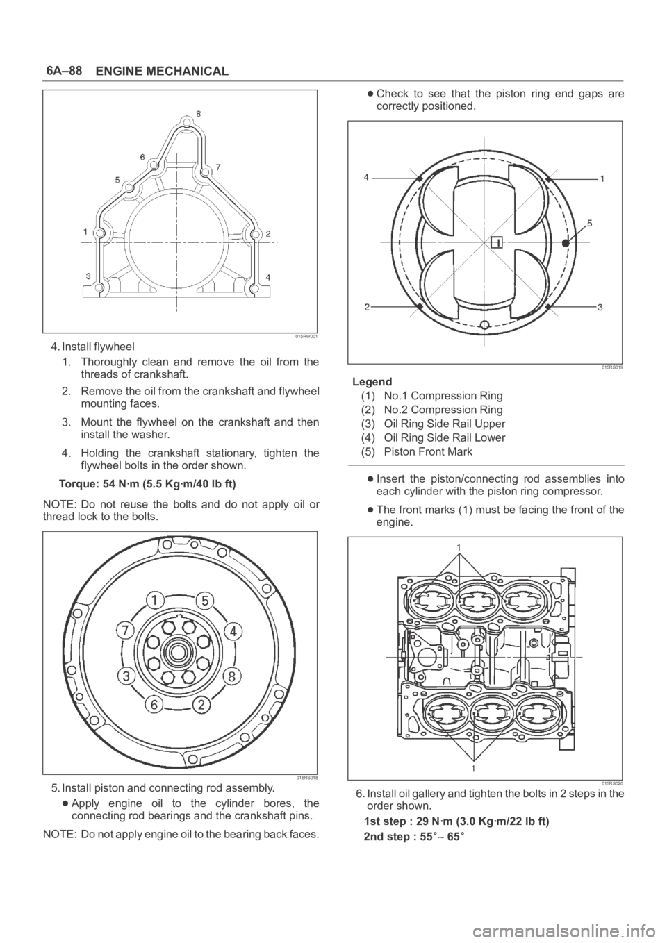
4. Install flywheel
1. Thoroughly clean and remove the oil from the
threads of crankshaft.
2. Remove the oil from the crankshaft and flywheel
mounting faces.
3. Mount the flywheel on the crankshaft and then
install the washer.
4. Holding the crankshaft stationary, tighten the
flywheel bolts in the order shown.
Torque: 54 Nꞏm (5.5 Kgꞏm/40 lb ft)
NOTE: Do not reuse the bolts and do not apply oil or
thread lock to the bolts.
015RS018
5. Install piston and connecting rod assembly.
Apply engine oil to the cylinder bores, the
connecting rod bearings and the crankshaft pins.
NOTE: Do not apply engine oil to the bearing back faces.
Check to see that the piston ring end gaps are
correctly positioned.
015RS019
Legend
(1) No.1 Compression Ring
(2) No.2 Compression Ring
(3) Oil Ring Side Rail Upper
(4) Oil Ring Side Rail Lower
(5) Piston Front Mark
Insert the piston/connecting rod assemblies into
each cylinder with the piston ring compressor.
The front marks (1) must be facing the front of the
engine.
015RS020
6. Install oil gallery and tighten the bolts in 2 steps in the
order shown.
1st step : 29 Nꞏm (3.0 Kgꞏm/22 lb ft)
2nd step : 55
65
Page 4589 of 6000
6A–93
ENGINE MECHANICAL
Crankshaft main bearing, Flywheel, Crankcase, Oil pan, Timing belt tensioner, Timing pulley, Timing belt
cover, Oil pump, Oil gallery, Oil strainer and Water pump
Nꞏm (Kgꞏm/Ib ft)
E06RW039
Page 4599 of 6000
6B–6
ENGINE COOLING
Draining and Refilling Cooling
System
Before draining the cooling system, inspect the system
and perform any necessary service to ensure that it is
clean, does not leak and is in proper working order. The
engine coolant (EC) level should be between the “MIN”
and “MAX” lines of reserve tank when the engine is cold.
If low, check for leakage and add EC up to the “MAX” line.
There should not be any excessive deposit of rust or
scales around the radiator cap or radiator filler hole, and
the EC should also be free from oil.
Replace the EC if excessively dirty.
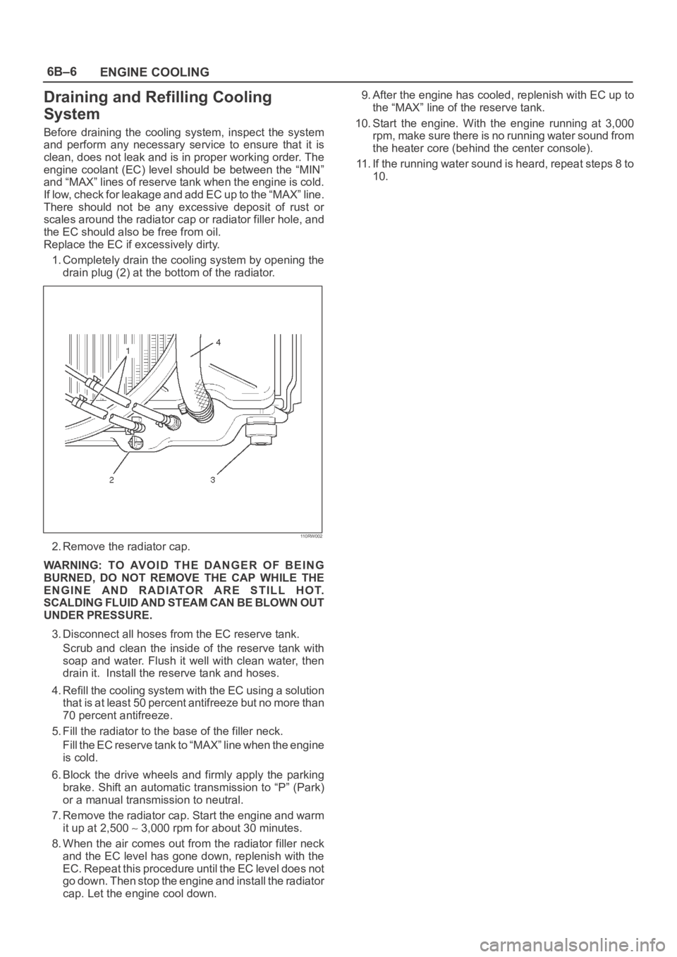
1. Completely drain the cooling system by opening the
drain plug (2) at the bottom of the radiator.
110RW002
2. Remove the radiator cap.
WARNING: TO AVOID THE DANGER OF BEING
BURNED, DO NOT REMOVE THE CAP WHILE THE
ENGINE AND RADIATOR ARE STILL HOT.
SCALDING FLUID AND STEAM CAN BE BLOWN OUT
UNDER PRESSURE.
3. Disconnect all hoses from the EC reserve tank.
Scrub and clean the inside of the reserve tank with
soap and water. Flush it well with clean water, then
drain it. Install the reserve tank and hoses.
4. Refill the cooling system with the EC using a solution
that is at least 50 percent antifreeze but no more than
70 percent antifreeze.
5. Fill the radiator to the base of the filler neck.
Fill the EC reserve tank to “MAX” line when the engine
is cold.
6. Block the drive wheels and firmly apply the parking
brake. Shift an automatic transmission to “P” (Park)
or a manual transmission to neutral.
7. Remove the radiator cap. Start the engine and warm
it up at 2,500
3,000 rpm for about 30 minutes.
8. When the air comes out from the radiator filler neck
and the EC level has gone down, replenish with the
EC. Repeat this procedure until the EC level does not
go down. Then stop the engine and install the radiator
cap. Let the engine cool down.9. After the engine has cooled, replenish with EC up to
the “MAX” line of the reserve tank.
10. Start the engine. With the engine running at 3,000
rpm, make sure there is no running water sound from
the heater core (behind the center console).
11. If the running water sound is heard, repeat steps 8 to
10.
Page 4614 of 6000
6C–7
ENGINE FUEL
Fuel Pump Relay
General Description
In order to control the FP operation, the FP relay is
provided. When the starter switch is turned to “ON”
position, the FP relay operates the FP for 2 seconds.When it is turned to “START” position, the Power Train
Control Module (PCM) receives the reference pulse from
the Ignition Control Module and it operates the relay,
again causing the FP to feed fuel.
Fuel Tank
Fuel Tank and Associated Parts
035RW048
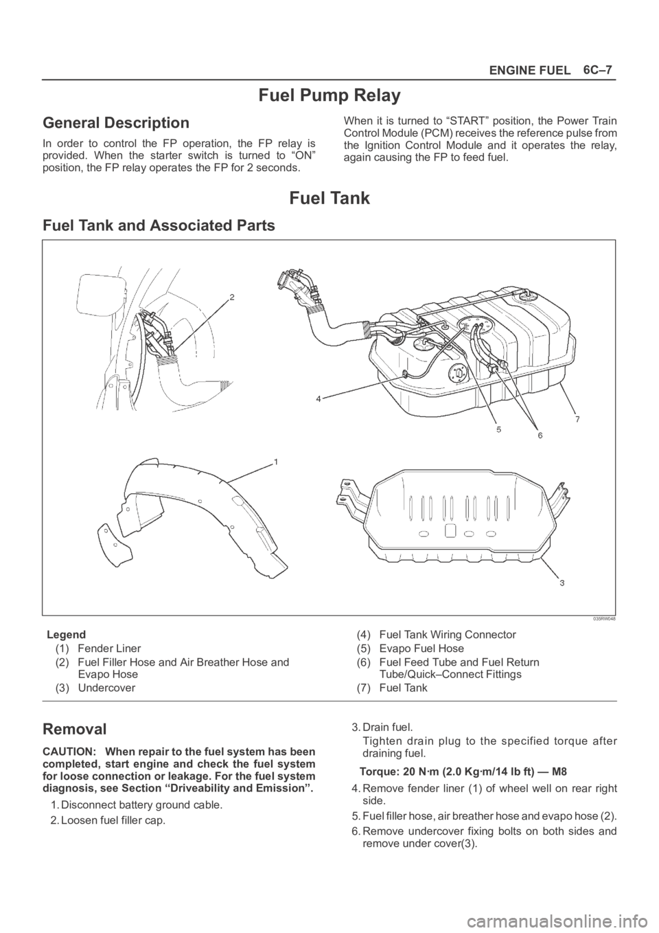
Legend
(1) Fender Liner
(2) Fuel Filler Hose and Air Breather Hose and
Evapo Hose
(3) Undercover(4) Fuel Tank Wiring Connector
(5) Evapo Fuel Hose
(6) Fuel Feed Tube and Fuel Return
Tube/Quick–Connect Fittings
(7) Fuel Tank
Removal
CAUTION: When repair to the fuel system has been
completed, start engine and check the fuel system
for loose connection or leakage. For the fuel system
diagnosis, see Section “Driveability and Emission”.
1. Disconnect battery ground cable.
2. Loosen fuel filler cap.3. Drain fuel.
Tighten drain plug to the specified torque after
draining fuel.
Torque: 20 Nꞏm (2.0 Kgꞏm/14 lb ft) — M8
4. Remove fender liner (1) of wheel well on rear right
side.
5. Fuel filler hose, air breather hose and evapo hose (2).
6. Remove undercover fixing bolts on both sides and
remove under cover(3).
Page 4615 of 6000
6C–8
ENGINE FUEL
7. Disconnect two fuel tank wiring connectors(4) on
front right side of tank.
8. Disconnect evapo fuel hose(5).
9. Disconnect fuel feed tube and fuel return tube(6).
NOTE: Handling of the fuel tube, be sure to refer “Fuel
Tube/Quick–Connect Fittings” in this section.
10. Remove fuel tank fixing bolts on both sides and
remove fuel tank(7).
Installation
1. Install fuel tank(7).
Place a flange on right side of tank on the bracket.
Install a flange on left side on the bracket from the
bottom, and tighten bolts to the specified torque.
Torque: 36 Nꞏm (3.7 Kgꞏm/27 lb ft)
2. Connect fuel feed tube and fuel return tube(6).
3. Connect evapo fuel hose(5).
4. Connect fuel tank wiring connector(4).
5. Install undercover(3).
6. Connect fuel filler hose, air breather hose and evapo
hose(2).
7. Install fender liner(1).
Mount fender liner to the wheel well.
Fill the tank with fuel and tighten fuel filler cap.
Connect battery ground cable.
Fuel Tube / Quick – Connect Fittings
Precautions
Lighting of Fires Prohibited.
Keep flames away from your work area to prevent the
inflammable from catching fire.
Disconnect the battery negative cable to prevent
shorting during work.
When welding or conducting other heat-generating
work on other parts, be sure to provide pretreatment
to protect the piping system from thermal damage or
spattering.
Cautions During Work
Do not expose the assembly to battery electrolyte or do
not wipe the assembly with a cloth used to wipe off spilt
battery electorolyte.
The piping wet with battery electrolyte cannot be used.
Be careful not to give a bending or twisting force to the
piping during the work. If deformed, replace with a new
piping.
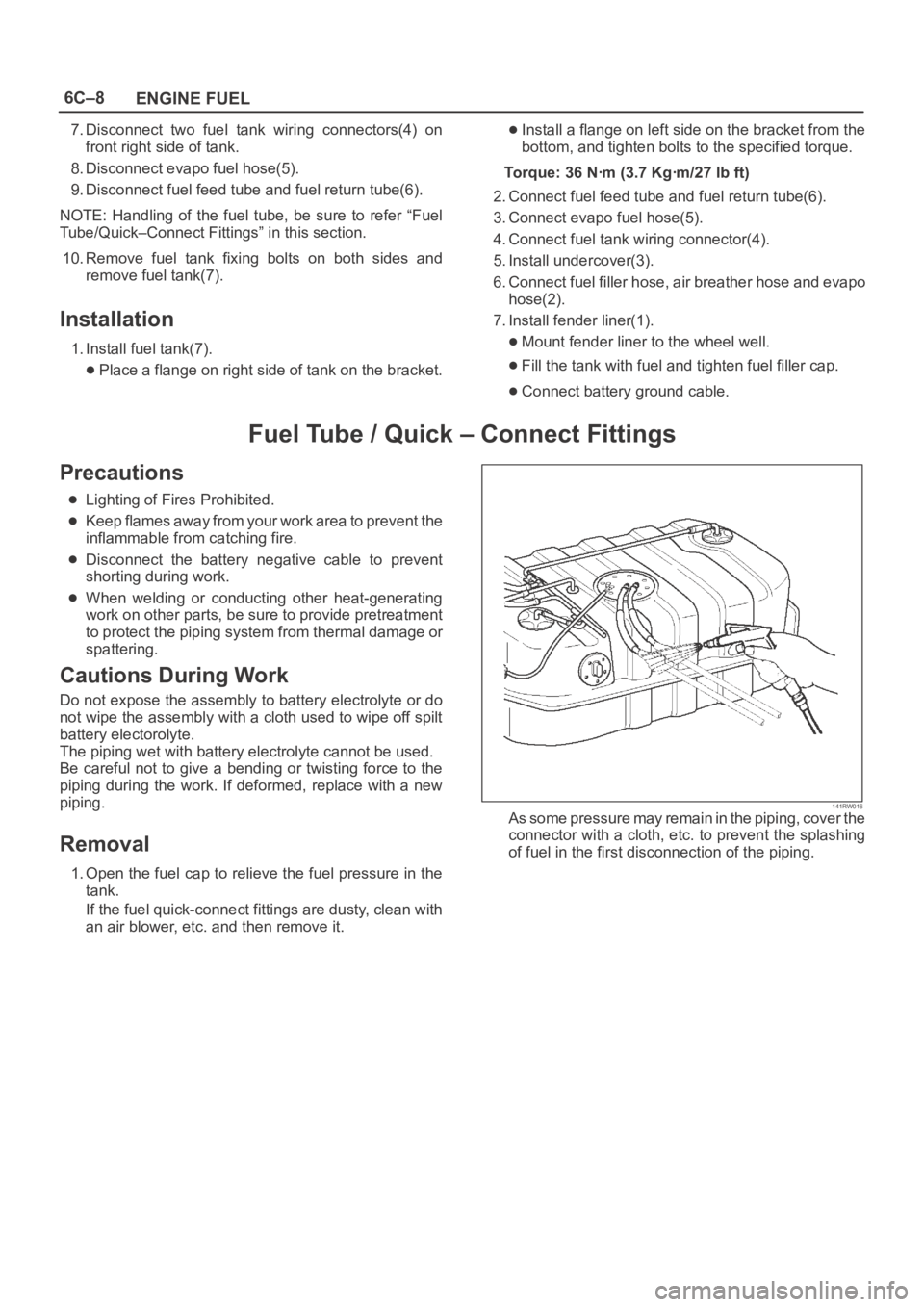
Removal
1. Open the fuel cap to relieve the fuel pressure in the
tank.
If the fuel quick-connect fittings are dusty, clean with
an air blower, etc. and then remove it.
141RW016As some pressure may remain in the piping, cover the
connector with a cloth, etc. to prevent the splashing
of fuel in the first disconnection of the piping.
Page 4751 of 6000
6E–94
ENGINE DRIVEABILITY AND EMISSIONS
Idle Air Control (IAC) System Check
StepActionVa l u e ( s )Ye sNo
11. Ignition “OFF.”
2. Connect the Tech 2.
3. Set the parking brake.
4. Block the wheels.
5. Turn the air conditioning “OFF.”
6. Idle the engine in Park (A/T) or Neutral (M/T).
7. Operate the IAC test.
8. The engine speed should decrease and increase as
the IAC is cycled.
Does the RPM change?
—Go to Step 2Go to Step 3
2RPM should change smoothly.
Does the RPM change within the range specified?700-1500
RPM
—Go to Step 3
3Check the IAC passages.
Are the IAC passages OK?
—Go to Step 4Go to Step 5
4Clear any obstruction from the IAC passages.
Is the action complete?
—Verify repair—
5Replace the IAC. Refer to On-Vehicle Service, Idle Air
Control Valve.
Is the action complete?—Verify repair—