Page 5343 of 6000
6A – 70 ENGINE MECHANICAL
CRANKSHAFT
1
15
14
13
8
11
16
17
10
9
72
12
3
465
18
012RW023
Legend
(1) Cylinder Head
(2) Cylinder Head Gasket
(3) Flywheel’
(4) Cylinder Block Rear Plate (for A/T) or Flywheel
Housing (for M/T)
(5) Crankshaft Rear Oil Seal
(6) Retainer
(7) Timing Gear Case
(8) Crankshaft Front Oil Seal(9) Timing Gear Case
(10) Gasket
(11) Balance Shaft
(12) Crank Case
(13) Piston Cooling Oil Pipe
(14) Main Bearing Cap
(15) Crankshaft
(16) Crankshaft Timing Gear
(17) Piston and Connecting Rod Assembly
(18) Cylinder Block
Page 5344 of 6000
ENGINE MECHANICAL 6A – 71
DISASSEMBLY
1. Cylinder Head
1) Refer to “Cylinder head” in this manual.
2. Crankshaft Front Oil Seal
1) Use a plastic hammer and a screwdriver to tap
around the oil seal to free it from the gear case
cover.
Take care not to damage the oil seal fitting
surfaces.
3. Crankshaft Timing Gear
4. Timing Gear Case
5. Flywheel
6. Cylinder Block Rear Plate
7. Crankshaft Rear Oil Seal
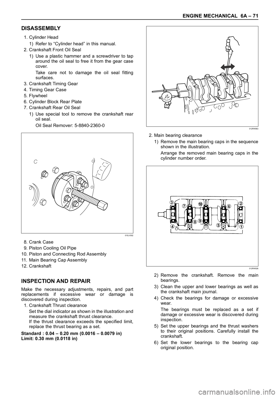
1) Use special tool to remove the crankshaft rear
oil seal.
Oil Seal Remover: 5-8840-2360-0
8. Crank Case
9. Piston Cooling Oil Pipe
10. Piston and Connecting Rod Assembly
11. Main Bearing Cap Assembly
12. Crankshaft
INSPECTION AND REPAIR
Make the necessary adjustments, repairs, and part
replacements if excessive wear or damage is
discovered during inspection.
1. Crankshaft Thrust clearance
Set the dial indicator as shown in the illustration and
measure the crankshaft thrust clearance.
If the thrust clearance exceeds the specified limit,
replace the thrust bearing as a set.
Standard : 0.04 – 0.20 mm (0.0016 – 0.0079 in)
Limit: 0.30 mm (0.0118 in)2. Main bearing clearance
1) Remove the main bearing caps in the sequence
shown in the illustration.
Arrange the removed main bearing caps in the
cylinder number order.
2) Remove the crankshaft. Remove the main
bearings.
3) Clean the upper and lower bearings as well as
the crankshaft main journal.
4) Check the bearings for damage or excessive
wear.
The bearings must be replaced as a set if
damage or excessive wear is discovered during
inspection.
5) Set the upper bearings and the thrust washers
to their original positions. Carefully install the
crankshaft.
6) Set the lower bearings to the bearing cap
original position.
015LV002
012RW063
371062
51
984
012RW026
Page 5350 of 6000
ENGINE MECHANICAL 6A – 77
8. Cylinder Block Rear Plate (A/T)
Align the rear plate with the cylinder block dowel
pins.
Tighten the rear plate to the specified torque.
Torque: 97 Nꞏm (9.9 kgꞏm/72 lb ft)
9. Flywheel housing (M/T)
Align the flywheel housing with the cylinder block
dowel pins.
Tighten the bolt to the specified torque.
Torque: 97 Nꞏm (9.9 kgꞏm/72 lb ft)
10. Flywheel
1) Thoroughly clean and remove the oil from the
threads of crankshaft and flywheel fixing
surface.
2) Mount the flywheel on the crankshaft and then
install the washer.
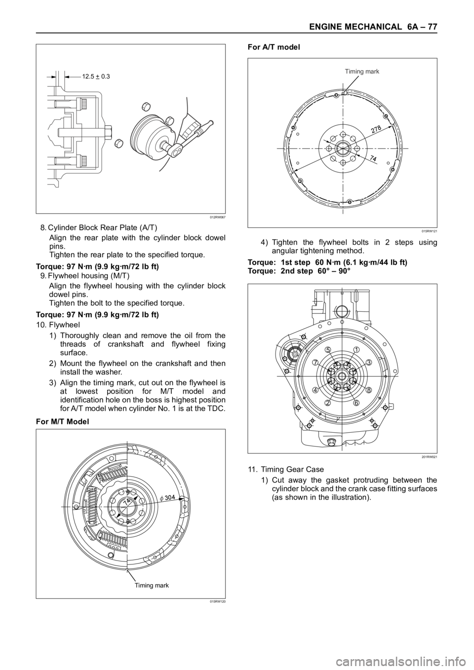
3) Align the timing mark, cut out on the flywheel is
at lowest position for M/T model and
identification hole on the boss is highest position
for A/T model when cylinder No. 1 is at the TDC.
For M/T ModelFor A/T model
4) Tighten the flywheel bolts in 2 steps using
angular tightening method.
Torque: 1st step 60 Nꞏm (6.1 kgꞏm/44 lb ft)
Torque: 2nd step 60° – 90°
11. Timing Gear Case
1) Cut away the gasket protruding between the
cylinder block and the crank case fitting surfaces
(as shown in the illustration).
12.5 + 0.3–
012RW067
Timing mark
2
7
8
74
015RW121
Timing mark
74φ
30
4
015RW120
751
3
8
6 2 4
201RW021
Page 5361 of 6000
6A – 88 ENGINE MECHANICAL
CYLINDER BLOCK
1
15
14
13
8
11
16
17
10
9
72
12
3
465
18
012RW023
Legend
(1) Cylinder Head
(2) Cylinder Head Gasket
(3) Flywheel
(4) Cylinder Block Rear Plate (A/T)
Flywheel Housing (M/T)
(5) Crankshaft Rear Oil Seal
(6) Retainer
(7) Timing Gear Case Cover
(8) Crankshaft Front Oil Seal(9) Timing Gear Case
(10) Gasket
(11) Balance Shaft
(12) Crank Case
(13) Piston Cooling Oil Pipe
(14) Main Bearing Cap
(15) Crankshaft
(16) Crankshaft Timing Gear
(17) Piston and Connecting Rod Assembly
(18) Cylinder Block
Page 5362 of 6000
ENGINE MECHANICAL 6A – 89
DISASSEMBLY
1. Cylinder Head Assembly
Refer to “Cylinder Head” in this manual.
2. Cylinder Head Gasket.
3. Flywheel
4. Cylinder Block Rear Plate (A/T), or Flywheel
housing (M/T).
5. Crankshaft Rear Oil Seal.
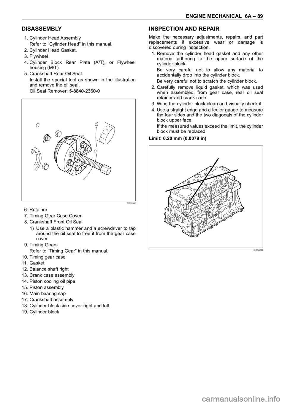
Install the special tool as shown in the illustration
and remove the oil seal.
Oil Seal Remover: 5-8840-2360-0
6. Retainer
7. Timing Gear Case Cover
8. Crankshaft Front Oil Seal
1) Use a plastic hammer and a screwdriver to tap
around the oil seal to free it from the gear case
cover.
9. Timing Gears
Refer to “Timing Gear” in this manual.
10. Timing gear case
11 . G a s k e t
12. Balance shaft right
13. Crank case assembly
14. Piston cooling oil pipe
15. Piston assembly
16. Main bearing cap
17. Crankshaft assembly
18. Cylinder block side cover right and left
19. Cylinder block
INSPECTION AND REPAIR
Make the necessary adjustments, repairs, and part
replacements if excessive wear or damage is
discovered during inspection.
1. Remove the cylinder head gasket and any other
material adhering to the upper surface of the
cylinder block.
Be very careful not to allow any material to
accidentally drop into the cylinder block.
Be very careful not to scratch the cylinder block.
2. Carefully remove liquid gasket, which was used
when assembled, from gear case, rear oil seal
retainer and crank case.
3. Wipe the cylinder block clean and visually check it.
4. Use a straight edge and a feeler gauge to measure
the four sides and the two diagonals of the cylinder
block upper face.
If the measured values exceed the limit, the cylinder
block must be replaced.
Limit: 0.20 mm (0.0079 in)
015RV002
012RW122
Page 5366 of 6000
ENGINE MECHANICAL 6A – 93
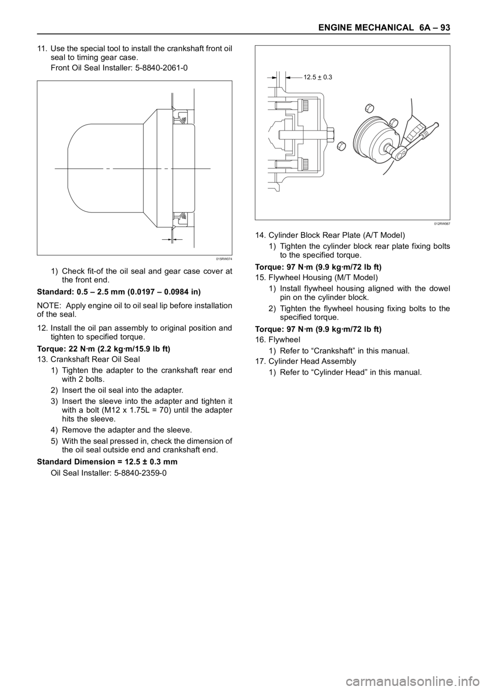
11. Use the special tool to install the crankshaft front oil
seal to timing gear case.
Front Oil Seal Installer: 5-8840-2061-0
1) Check fit-of the oil seal and gear case cover at
the front end.
Standard: 0.5 – 2.5 mm (0.0197 – 0.0984 in)
NOTE: Apply engine oil to oil seal lip before installation
of the seal.
12. Install the oil pan assembly to original position and
tighten to specified torque.
Torque: 22 Nꞏm (2.2 kgꞏm/15.9 lb ft)
13. Crankshaft Rear Oil Seal
1) Tighten the adapter to the crankshaft rear end
with 2 bolts.
2) Insert the oil seal into the adapter.
3) Insert the sleeve into the adapter and tighten it
with a bolt (M12 x 1.75L = 70) until the adapter
hits the sleeve.
4) Remove the adapter and the sleeve.
5) With the seal pressed in, check the dimension of
the oil seal outside end and crankshaft end.
Standard Dimension = 12.5 ± 0.3 mm
Oil Seal Installer: 5-8840-2359-014. Cylinder Block Rear Plate (A/T Model)
1) Tighten the cylinder block rear plate fixing bolts
to the specified torque.
Torque: 97 Nꞏm (9.9 kgꞏm/72 lb ft)
15. Flywheel Housing (M/T Model)
1) Install flywheel housing aligned with the dowel
pin on the cylinder block.
2) Tighten the flywheel housing fixing bolts to the
specified torque.
Torque: 97 Nꞏm (9.9 kgꞏm/72 lb ft)
16. Flywheel
1) Refer to “Crankshaft” in this manual.
17. Cylinder Head Assembly
1) Refer to “Cylinder Head” in this manual.
015RW074
12.5 + 0.3–
012RW067
Page 5367 of 6000
6A – 94 ENGINE MECHANICAL
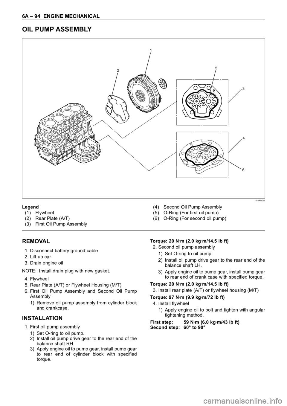
OIL PUMP ASSEMBLY
2
1
5
6
3
4
012RW097
Legend
(1) Flywheel
(2) Rear Plate (A/T)
(3) First Oil Pump Assembly(4) Second Oil Pump Assembly
(5) O-Ring (For first oil pump)
(6) O-Ring (For second oil pump)
REMOVAL
1. Disconnect battery ground cable
2. Lift up car
3. Drain engine oil
NOTE: Install drain plug with new gasket.
4. Flywheel
5. Rear Plate (A/T) or Flywheel Housing (M/T)
6. First Oil Pump Assembly and Second Oil Pump
Assembly
1) Remove oil pump assembly from cylinder block
and crankcase.
INSTALLATION
1. First oil pump assembly
1) Set O-ring to oil pump.
2) Install oil pump drive gear to the rear end of the
balance shaft RH.
3) Apply engine oil to pump gear, install pump gear
to rear end of cylinder block with specified
torque.Torque: 20 Nꞏm (2.0 kgꞏm/14.5 lb ft)
2. Second oil pump assembly
1) Set O-ring to oil pump.
2) Install oil pump drive gear to the rear end of the
balance shaft LH.
3) Apply engine oil to pump gear, install pump gear
to rear end of crank case with specified torque.
Torque: 20 Nꞏm (2.0 kgꞏm/14.5 lb ft)
3. Install rear plate (A/T) or flywheel housing (M/T)
Torque: 97 Nꞏm (9.9 kgꞏm/72 lb ft)
4. Install flywheel
1) Apply engine oil to bolt and tighten with angular
tightening method.
First step: 59 Nꞏm (6.0 kgꞏm/43 lb ft)
Second step: 60° to 90°
Page 5448 of 6000
6E–19 4JX1–TC ENGINE DRIVEABILITY AND EMISSIONS
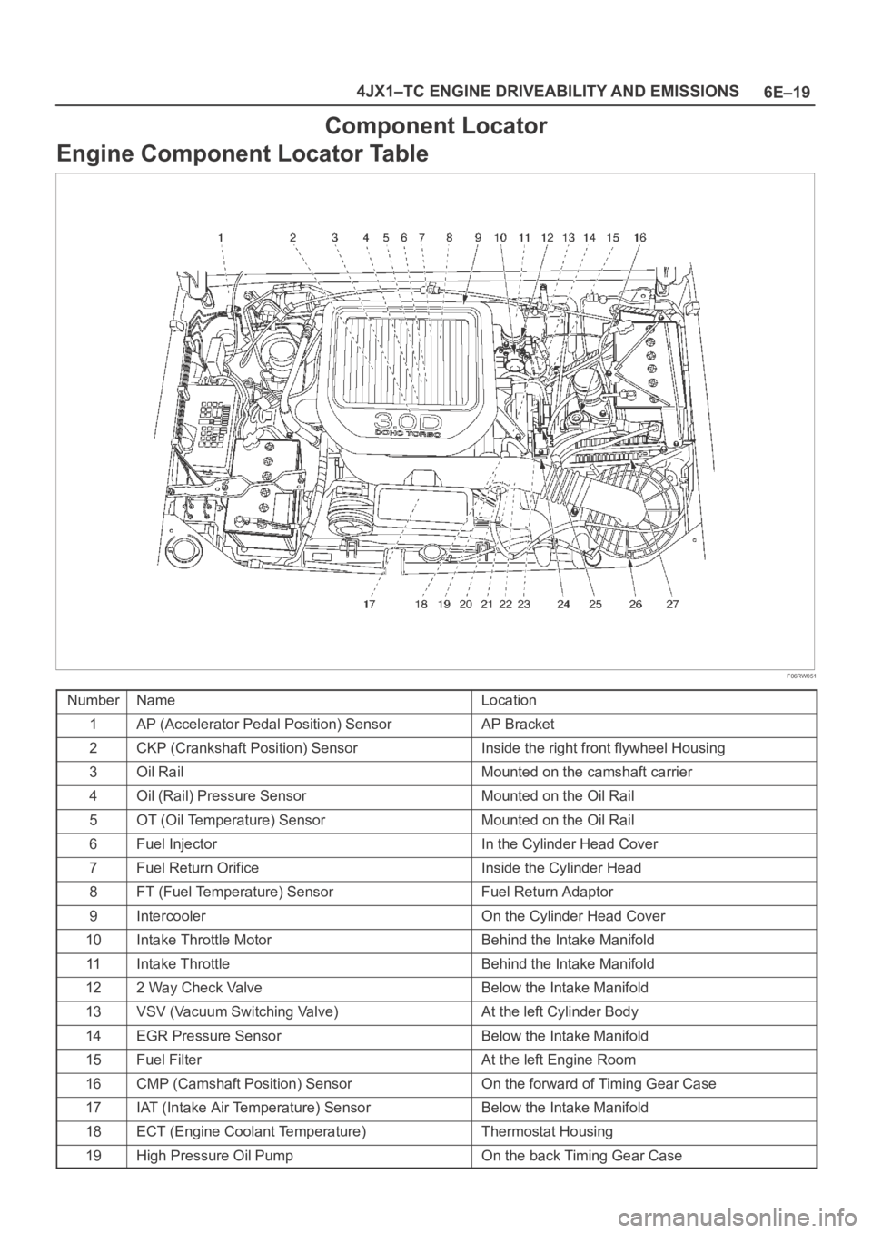
Component Locator
Engine Component Locator Table
F06RW051
NumberNameLocation
1AP (Accelerator Pedal Position) SensorAP Bracket
2CKP (Crankshaft Position) SensorInside the right front flywheel Housing
3Oil RailMounted on the camshaft carrier
4Oil (Rail) Pressure SensorMounted on the Oil Rail
5OT (Oil Temperature) SensorMounted on the Oil Rail
6Fuel InjectorIn the Cylinder Head Cover
7Fuel Return OrificeInside the Cylinder Head
8FT (Fuel Temperature) SensorFuel Return Adaptor
9IntercoolerOn the Cylinder Head Cover
10Intake Throttle MotorBehind the Intake Manifold
11Intake ThrottleBehind the Intake Manifold
122 Way Check ValveBelow the Intake Manifold
13VSV (Vacuum Switching Valve)At the left Cylinder Body
14EGR Pressure SensorBelow the Intake Manifold
15Fuel FilterAt the left Engine Room
16CMP (Camshaft Position) SensorOn the forward of Timing Gear Case
17IAT (Intake Air Temperature) SensorBelow the Intake Manifold
18ECT (Engine Coolant Temperature)Thermostat Housing
19High Pressure Oil PumpOn the back Timing Gear Case