Page 1741 of 6000
6A – 8 ENGINE MECHANICAL
Parts Items Service standard Service limit Remarks
Cylinder
Block—
95.421 – 95.450
(3.7567 – 3.7579)0.20 (0.0079) Warpage
(Upper surface of the cylinder block)
Cylinder bore diameter
Parts Items Service standard Service limit Remarks
Thermostat
Radiator cap83 – 87°C
(181 – 189°F)
More than 9.5 (0.374)
at 100°C (212°F)
88.2 – 117.6 kPa
(12.8 –17.0 psi) Valve opening temperature
Valve full open temperature and lift
Valve opening pressure
Engine Coolingmm (in) mm (in)
Page 1742 of 6000

ENGINE MECHANICAL 6A – 9
SERVICING
Servicing refers to general maintenance procedures to
be performed by qualified service personnel.
MODEL IDENTIFICATION
Engine Serial Number
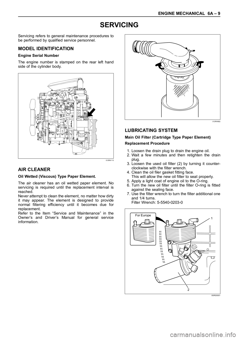
The engine number is stamped on the rear left hand
side of the cylinder body.
AIR CLEANER
Oil Wetted (Viscous) Type Paper Element.
The air cleaner has an oil wetted paper element. No
servicing is required until the replacement interval is
reached.
Never attempt to clean the element, no matter how dirty
it may appear. The element is designed to provide
normal filtering efficiency until it becomes due for
replacement.
Refer to the Item “Service and Maintenance” in the
Owner’s and Driver’s Manual for general service
information.
LUBRICATING SYSTEM
Main Oil Filter (Cartridge Type Paper Element)
Replacement Procedure
1. Loosen the drain plug to drain the engine oil.
2. Wait a few minutes and then retighten the drain
plug.
3. Loosen the used oil filter (2) by turning it counter-
clockwise with the filter wrench.
4. Clean the oil filer gasket fitting face.
This will allow the new oil filter to seat properly.
5. Apply a light coat of engine oil to the O-ring.
6. Turn the new oil filter until the filter O-ring is fitted
against the sealing face.
7. Use the filter wrench to turn the filter additional one
and 1/4 turns.
Filter Wrench: 5-5540-0203-0
012RW115
012RW062
For Europe1
2
050R200001
Page 1743 of 6000

6A – 10 ENGINE MECHANICAL
8. Check the engine oil level and replenish to the
specified level if required.
9. Start the engine and check for oil leakage from the
main oil filter.
FUEL SYSTEM
Fuel filter
Replacement Procedure
1. Loosen the used fuel filter by turning it
counterclockwise with the filter wrench.
Filter Wrench : 5-8840-0203-0
2. Clean the filter cover fitting faces.
This will allow the new fuel filter to seat properly.
3. Apply a light coat of engine oil to the O-ring.
4. Turn the fuel filter until the sealing face comes in
contact with the O-ring.
5. Turn the fuel filter with a filter wrench 2/3 of a turn
until sealed.
Filter Wrench: 5-8840-0203-0Legend
(1) Priming pump
6. Operate the priming pump until the air is discharged
completely from fuel system.
NOTE: The use of an Isuzu genuine fuel filter is
strongly recommended.
COOLING SYSTEM
Coolant Level
Check the coolant level and replenish the radiator
reserve tank as necessary.
If the coolant level falls below the “‘MIN” line, carefully
check the cooling system for leakage. Then add
enough coolant to bring the level up to the “MAX” line.
NOTE: Do not overfill the reserve tank.
012RW112
012RW078
1
012RW111
012RW080
Page 1763 of 6000
6A – 30 ENGINE MECHANICAL
ENGINE MOUNT (RH)
REMOVAL
1. Disconnect battery ground cable
2. Hang the engine assembly.
3. Rubber engine mount.
1) Remove bolts from chassis frame bracket.
2) Remove nuts from rubber engine mount and
engine mounting bracket.
4. Remove bolt which is fixed between engine and
mounting bracket then remove the engine mounting
bracket.
INSTALLATION
Tighten the fixing bolts to the specified torque.
1. Engine mounting bracket to cylinder block.
Torque : 40 Nꞏm (4 kgꞏm/29 lb ft) (for M10)
127 Nꞏm (13 kgꞏm/94 lb ft) (for M14)
2. Rubber engine mount to chassis frame and engine
mounting bracket.
Torque :40 Nꞏm (4 kgꞏm/29 lb ft)
43
12
022RW018
Legend
(1) Rubber Engine Mount (LH)
(2) Engine Mounting Bracket (LH)
(3) Rubber Engine Mount (RH)
(4) Engine Mounting Bracket (RH)
Page 1764 of 6000
ENGINE MECHANICAL 6A – 31
ENGINE MOUNT (LH)
REMOVAL
1. Disconnect battery ground cable
2. Hang the engine assembly.
3. Rubber engine mount.
1) Remove bolts from chassis frame bracket.
2) Remove nuts from rubber engine mount and
engine mounting bracket.
4. Remove bolt which is fixed between engine and
mounting bracket then remove the engine mounting
bracket.
INSTALLATION
Tighten the fixing bolts to the specified torque.
1. Engine mounting bracket to cylinder block.
Torque : 40 Nꞏm (4 kgꞏm/29 lb ft) (for M10)
127 Nꞏm (13 kgꞏm/94 lb ft) (for M14)
2. Rubber engine mount to chassis frame and engine
mounting bracket.
Torque :40 Nꞏm (4 kgꞏm/29 lb ft)
43
12
022RW018
Legend
(1) Rubber Engine Mount (LH)
(2) Engine Mounting Bracket (LH)
(3) Rubber Engine Mount (RH)
(4) Engine Mounting Bracket (RH)
Page 1774 of 6000

ENGINE MECHANICAL 6A – 41
CYLINDER HEAD
3
4
1
2
012RW096
Legend
(1) Glow Plug
(2) Plate
(3) Cylinder Head Bolt
(4) Cylinder Head
NOTE:
During disassembly, be sure that the valve train
components are kept together and identified so that
they can be re-installed in their original locations.
Before removing the cylinder head from the engine
and before disassembling the valve mechanism, do
a compression test and note the results.
DISASSEMBLY
1. Injector Assy
2. Glow Plug and Glow Plug Connector
3. Cylinder Head Assembly
Refer to “Cylinder Head Gasket”
CLEAN
Cylinder head
Carefully remove all varnish, soot and carbon on
the bare metal. Do not use a motorized wire brush
on any gasket sealing surface.
INSPECTION AND REPAIR
Make the necessary adjustments, repairs, and part
replacements if excessive wear or damage is
discovered during inspection.
1. Cylinder head gasket and mating surfaces for
leaks, corrosion and blow-by. If the gasket has
failed, determine the cause;
– Improper installation
– Loosen or warped cylinder head
– Insufficient torque on head bolts
– Warped cylinder block surface
Page 1776 of 6000
ENGINE MECHANICAL 6A – 43
CYLINDER HEAD GASKET
12
13
14
15
8
3
4
5 6
10
11 9
With
spacer type
Without
spacer type
1 7
2
011R200002
Legend
(1) Cylinder Head Noise Insulator Cover
(2) Insulator
(3) Bolt and Gasket
(4) Oil Seal
(5) Gasket
(6) Cylinder Head Cover
(7) Bolt, Stud and Rubber Mounting
(8) Injector Clamp(9) Oil Rail
(10) Injector Assembly
(11) Camshaft Carrier
(12) Cylinder Head Bolt
(13) Cylinder Head Assembly
(14) Cylinder Head Gasket
(15) Cylinder Block
Page 1781 of 6000

6A – 48 ENGINE MECHANICAL
DISASSEMBLY
1. Injector clamp
2. Injector assembly
3. Oil rail assembly
4. Camshaft bracket
5. Camshaft
6. Oil seal
7. Plug
NOTE: Before starting disassembly above, drain oil
from oil rail to prevent oil from entering the cylinder.
REASSEMBLY
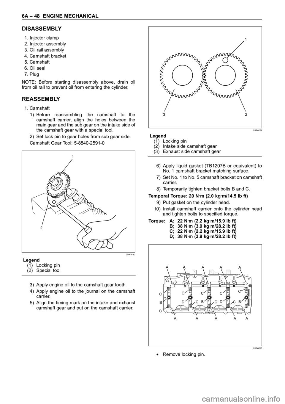
1. Camshaft
1) Before reassembling the camshaft to the
camshaft carrier, align the holes between the
main gear and the sub gear on the intake side of
the camshaft gear with a special tool.
2) Set lock pin to gear holes from sub gear side.
Camshaft Gear Tool: 5-8840-2591-0
Legend
(1) Locking pin
(2) Special tool
3) Apply engine oil to the camshaft gear tooth.
4) Apply engine oil to the journal on the camshaft
carrier.
5) Align the timing mark on the intake and exhaust
camshaft gear and put on the camshaft carrier.Legend
(1) Locking pin
(2) Intake side camshaft gear
(3) Exhaust side camshaft gear
6) Apply liquid gasket (TB1207B or equivalent) to
No. 1 camshaft bracket matching surface.
7) Set No. 1 to No. 5 camshaft bracket on camshaft
carrier.
8) Temporarily tighten bracket bolts B and C.
Temporal Torque: 20 Nꞏm (2.0 kgꞏm/14.5 lb ft)
9) Put gasket on the cylinder head.
10) Install camshaft carrier onto the cylinder head
and tighten bolts to specified torque.
Torque: A; 22 Nꞏm (2.2 kgꞏm/15.9 lb ft)
B; 38 Nꞏm (3.9 kgꞏm/28.2 lb ft)
C; 22 Nꞏm (2.2 kgꞏm/15.9 lb ft)
D; 38 Nꞏm (3.9 kgꞏm/28.2 lb ft)
Remove locking pin.
1
2
014RW183
321
014RW184
CC
D
B
CC
B
CC
D
CC
B
C
A AA A A A
AAAA
011RW035