1998 OPEL FRONTERA check oil
[x] Cancel search: check oilPage 3515 of 6000
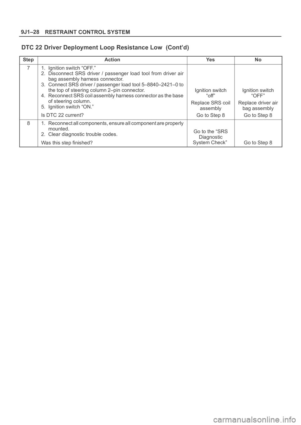
RESTRAINT CONTROL SYSTEM 9J1–28
DTC 22 Driver Deployment Loop Resistance Low (Cont’d)
StepNo Ye s Action
71. Ignition switch “OFF.”
2. Disconnect SRS driver / passenger load tool from driver air
bag assembly harness connector.
3. Connect SRS driver / passenger load tool 5–8840–2421–0 to
the top of steering column 2–pin connector.
4. Reconnect SRS coil assembly harness connector as the base
of steering column.
5. Ignition switch “ON.”
Is DTC 22 current?
Ignition switch
“off”
Replace SRS coil
assembly
Go to Step 8Ignition switch
“OFF”
Replace driver air
bag assembly
Go to Step 8
81. Reconnect all components, ensure all component are properly
mounted.
2. Clear diagnostic trouble codes.
Was this step finished?
Go to the “SRS
Diagnostic
System Check”
Go to Step 8
Page 3517 of 6000
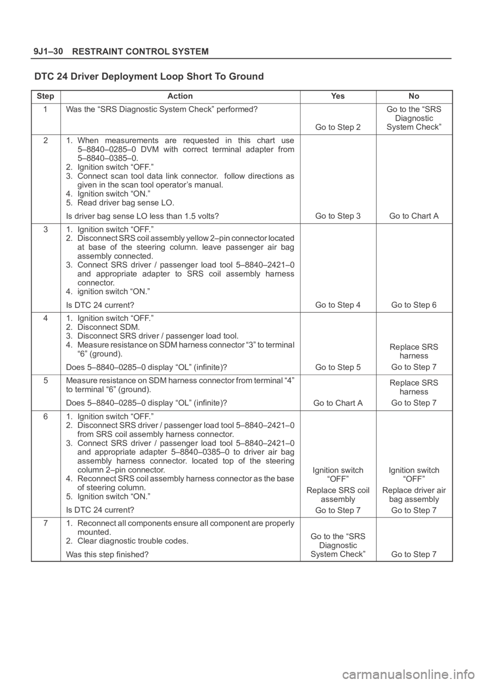
RESTRAINT CONTROL SYSTEM 9J1–30
DTC 24 Driver Deployment Loop Short To Ground
StepActionYe sNo
1Was the “SRS Diagnostic System Check” performed?
Go to Step 2
Go to the “SRS
Diagnostic
System Check”
21. When measurements are requested in this chart use
5–8840–0285–0 DVM with correct terminal adapter from
5–8840–0385–0.
2. Ignition switch “OFF.”
3. Connect scan tool data link connector. follow directions as
given in the scan tool operator’s manual.
4. Ignition switch “ON.”
5. Read driver bag sense LO.
Is driver bag sense LO less than 1.5 volts?
Go to Step 3Go to Chart A
31. Ignition switch “OFF.”
2. Disconnect SRS coil assembly yellow 2–pin connector located
at base of the steering column. leave passenger air bag
assembly connected.
3. Connect SRS driver / passenger load tool 5–8840–2421–0
and appropriate adapter to SRS coil assembly harness
connector.
4. ignition switch “ON.”
Is DTC 24 current?
Go to Step 4Go to Step 6
41. Ignition switch “OFF.”
2. Disconnect SDM.
3. Disconnect SRS driver / passenger load tool.
4. Measure resistance on SDM harness connector “3” to terminal
“6” (ground).
Does 5–8840–0285–0 display “OL” (infinite)?
Go to Step 5
Replace SRS
harness
Go to Step 7
5Measure resistance on SDM harness connector from terminal “4”
to terminal “6” (ground).
Does 5–8840–0285–0 display “OL” (infinite)?
Go to Chart A
Replace SRS
harness
Go to Step 7
61. Ignition switch “OFF.”
2. Disconnect SRS driver / passenger load tool 5–8840–2421–0
from SRS coil assembly harness connector.
3. Connect SRS driver / passenger load tool 5–8840–2421–0
and appropriate adapter 5–8840–0385–0 to driver air bag
assembly harness connector. located top of the steering
column 2–pin connector.
4. Reconnect SRS coil assembly harness connector as the base
of steering column.
5. Ignition switch “ON.”
Is DTC 24 current?
Ignition switch
“OFF”
Replace SRS coil
assembly
Go to Step 7Ignition switch
“OFF”
Replace driver air
bag assembly
Go to Step 7
71. Reconnect all components ensure all component are properly
mounted.
2. Clear diagnostic trouble codes.
Was this step finished?
Go to the “SRS
Diagnostic
System Check”
Go to Step 7
Page 3519 of 6000
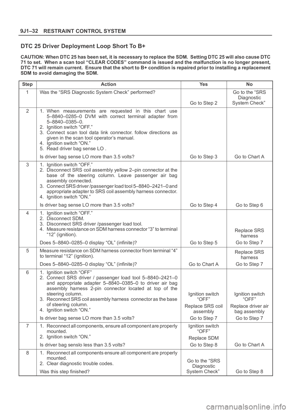
RESTRAINT CONTROL SYSTEM 9J1–32
DTC 25 Driver Deployment Loop Short To B+
CAUTION: When DTC 25 has been set, it is necessary to replace the SDM. Setting DTC 25 will also cause DTC
71 to set. When a scan tool “CLEAR CODES” command is issued and the malfunction is no longer present,
DTC 71 will remain current. Ensure that the short to B+ condition is repaired prior to installing a replacement
SDM to avoid damaging the SDM.
Step
ActionYe sNo
1Was the “SRS Diagnostic System Check” performed?
Go to Step 2
Go to the “SRS
Diagnostic
System Check”
21. When measurements are requested in this chart use
5–8840–0285–0 DVM with correct terminal adapter from
5–8840–0385–0.
2. Ignition switch “OFF.”
3. Connect scan tool data link connector. follow directions as
given in the scan tool operator’s manual.
4. Ignition switch “ON.”
5. Read driver bag sense LO .
Is driver bag sense LO more than 3.5 volts?
Go to Step 3Go to Chart A
31. Ignition switch “OFF.”
2. Disconnect SRS coil assembly yellow 2–pin connector at the
base of the steering column. Leave passenger air bag
assembly connected.
3. Connect SRS driver /passenger load tool 5–8840–2421–0 and
appropriate adapter to SRS coil assembly harness connector.
4. Ignition switch “ON.”
Is driver bag sense LO more than 3.5 volts?
Go to Step 4Go to Step 6
41. Ignition switch “OFF.”
2. Disconnect SDM.
3. Disconnect SRS driver /passenger load tool.
4. Measure resistance on SDM harness connector “3” to terminal
“12” (ignition).
Does 5–8840–0285–0 display “OL” (infinite)?
Go to Step 5
Replace SRS
harness
Go to Step 7
5Measure resistance on SDM harness connector from terminal “4”
to terminal “12” (ignition).
Does 5–8840–0285–0 display “OL” (infinite)?
Go to Chart A
Replace SRS
harness
Go to Step 7
61. Ignition switch “OFF”
2. Connect SRS driver / passenger load tool 5–8840–2421–0
and appropriate adapter 5–8840–0385–0 to driver air bag
assembly harness 2-pin connector located at top of the
steering column.
3. Reconnect SRS coil assembly harness connector as the base
of steering column.
4. Ignition switch “ON.”
Is driver bag sense LO more than 3.5 volts?
Ignition switch
“OFF”
Replace SRS coil
assembly
Go to Step 7Ignition switch
“OFF”
Replace driver air
bag assembly
Go to Step 7
71. Reconnect all components, ensure all component are properly
mounted.
2. Ignition switch “ON.”
Is driver bag senslo less than 3.5 volts?Ignition switch
“OFF”
Replace SDM
Go to Step 8
Go to Chart A
81. Reconnect all components ensure all component are properly
mounted.
2. Clear diagnostic trouble codes.
Was this step finished?
Go to the “SRS
Diagnostic
System Check”
Go to Step 8
Page 3520 of 6000
9J1–33
RESTRAINT CONTROL SYSTEM
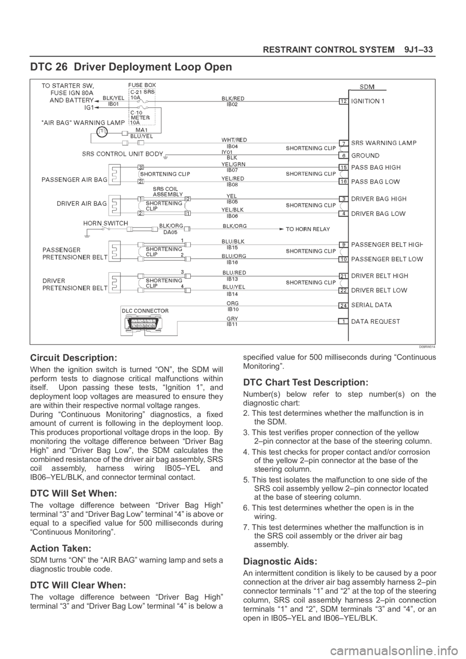
DTC 26 Driver Deployment Loop Open
D09RW014
Circuit Description:
When the ignition switch is turned “ON”, the SDM will
perform tests to diagnose critical malfunctions within
itself. Upon passing these tests, “Ignition 1”, and
deployment loop voltages are measured to ensure they
are within their respective normal voltage ranges.
During “Continuous Monitoring” diagnostics, a fixed
amount of current is following in the deployment loop.
This produces proportional voltage drops in the loop. By
monitoring the voltage difference between “Driver Bag
High” and “Driver Bag Low”, the SDM calculates the
combined resistance of the driver air bag assembly, SRS
coil assembly, harness wiring IB05–YEL and
IB06–YEL/BLK, and connector terminal contact.
DTC Will Set When:
The voltage difference between “Driver Bag High”
terminal “3” and “Driver Bag Low” terminal “4” is above or
equal to a specified value for 500 milliseconds during
“Continuous Monitoring”.
Action Taken:
SDM turns “ON” the “AIR BAG” warning lamp and sets a
diagnostic trouble code.
DTC Will Clear When:
The voltage difference between “Driver Bag High”
terminal “3” and “Driver Bag Low” terminal “4” is below aspecified value for 500 milliseconds during “Continuous
Monitoring”.
DTC Chart Test Description:
Number(s) below refer to step number(s) on the
diagnostic chart:
2. This test determines whether the malfunction is in
the SDM.
3. This test verifies proper connection of the yellow
2–pin connector at the base of the steering column.
4. This test checks for proper contact and/or corrosion
of the yellow 2–pin connector at the base of the
steering column.
5. This test isolates the malfunction to one side of the
SRS coil assembly yellow 2–pin connector located
at the base of steering column.
6. This test determines whether the open is in the
wiring.
7. This test determines whether the malfunction is in
the SRS coil assembly or the driver air bag
assembly.
Diagnostic Aids:
An intermittent condition is likely to be caused by a poor
connection at the driver air bag assembly harness 2–pin
connector terminals “1” and “2” at the top of the steering
column, SRS coil assembly harness 2–pin connection
terminals “1” and “2”, SDM terminals “3” and “4”, or an
open in IB05–YEL and IB06–YEL/BLK.
Page 3521 of 6000
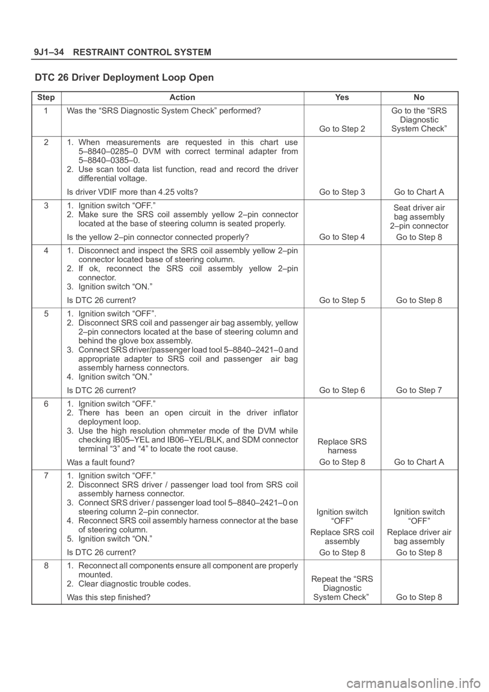
RESTRAINT CONTROL SYSTEM 9J1–34
DTC 26 Driver Deployment Loop Open
StepActionYe sNo
1Was the “SRS Diagnostic System Check” performed?
Go to Step 2
Go to the “SRS
Diagnostic
System Check”
21. When measurements are requested in this chart use
5–8840–0285–0 DVM with correct terminal adapter from
5–8840–0385–0.
2. Use scan tool data list function, read and record the driver
differential voltage.
Is driver VDIF more than 4.25 volts?
Go to Step 3Go to Chart A
31. Ignition switch “OFF.”
2. Make sure the SRS coil assembly yellow 2–pin connector
located at the base of steering column is seated properly.
Is the yellow 2–pin connector connected properly?
Go to Step 4
Seat driver air
bag assembly
2–pin connector
Go to Step 8
41. Disconnect and inspect the SRS coil assembly yellow 2–pin
connector located base of steering column.
2. If ok, reconnect the SRS coil assembly yellow 2–pin
connector.
3. Ignition switch “ON.”
Is DTC 26 current?
Go to Step 5Go to Step 8
51. Ignition switch “OFF”.
2. Disconnect SRS coil and passenger air bag assembly, yellow
2–pin connectors located at the base of steering column and
behind the glove box assembly.
3. Connect SRS driver/passenger load tool 5–8840–2421–0 and
appropriate adapter to SRS coil and passenger air bag
assembly harness connectors.
4. Ignition switch “ON.”
Is DTC 26 current?
Go to Step 6Go to Step 7
61. Ignition switch “OFF.”
2. There has been an open circuit in the driver inflator
deployment loop.
3. Use the high resolution ohmmeter mode of the DVM while
checking IB05–YEL and IB06–YEL/BLK, and SDM connector
terminal “3” and “4” to locate the root cause.
Was a fault found?
Replace SRS
harness
Go to Step 8
Go to Chart A
71. Ignition switch “OFF.”
2. Disconnect SRS driver / passenger load tool from SRS coil
assembly harness connector.
3. Connect SRS driver / passenger load tool 5–8840–2421–0 on
steering column 2–pin connector.
4. Reconnect SRS coil assembly harness connector at the base
of steering column.
5. Ignition switch “ON.”
Is DTC 26 current?
Ignition switch
“OFF”
Replace SRS coil
assembly
Go to Step 8Ignition switch
“OFF”
Replace driver air
bag assembly
Go to Step 8
81. Reconnect all components ensure all component are properly
mounted.
2. Clear diagnostic trouble codes.
Was this step finished?
Repeat the “SRS
Diagnostic
System Check”
Go to Step 8
Page 3767 of 6000
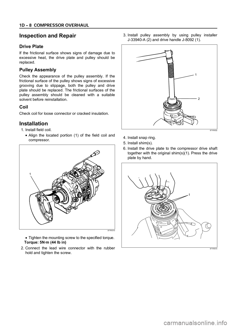
Inspection and Repair
Drive Plate
If the frictional surface shows signs of damage due to
excessive heat, the drive plate and pulley should be
replaced.
Pulley Assembly
Check the appearance of the pulley assembly. If the
frictional surface of the pulley shows signs of excessive
grooving due to slippage, both the pulley and drive
plate should be replaced. The frictional surfaces of the
pulley assembly should be cleaned with a suitable
solvent before reinstallation.
Coil
Check coil for loose connector or cracked insulation.
Installation
1. Install field coil.
Align the located portion (1) of the field coil and
compressor.
Tighten the mounting screw to the specified torque.
Torque: 5Nꞏm (44 lb in)
2. Connect the lead wire connector with the rubber
hold and tighten the screw.3. Install pulley assembly by using pulley installer
J-33940-A (2) and drive handle J-8092 (1).
4. Install snap ring.
5. Install shim(s).
6. Install the drive plate to the compressor drive shaft
together with the original shim(s)(1). Press the drive
plate by hand.
1
2
871RX032
1
871RX010
1
871RX015
Page 3782 of 6000
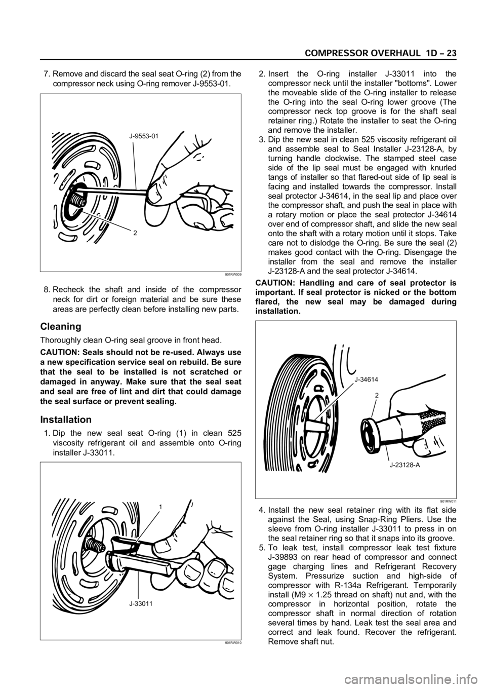
7. Remove and discard the seal seat O-ring (2) from the
compressor neck using O-ring remover J-9553-01.
8. Recheck the shaft and inside of the compressor
neck for dirt or foreign material and be sure these
areas are perfectly clean before installing new parts.
Cleaning
Thoroughly clean O-ring seal groove in front head.
CAUTION: Seals should not be re-used. Always use
a new specification service seal on rebuild. Be sure
that the seal to be installed is not scratched or
damaged in anyway. Make sure that the seal seat
and seal are free of lint and dirt that could damage
the seal surface or prevent sealing.
Installation
1. Dip the new seal seat O-ring (1) in clean 525
viscosity refrigerant oil and assemble onto O-ring
installer J-33011.2. Insert the O-ring installer J-33011 into the
compressor neck until the installer "bottoms". Lower
the moveable slide of the O-ring installer to release
the O-ring into the seal O-ring lower groove (The
compressor neck top groove is for the shaft seal
retainer ring.) Rotate the installer to seat the O-ring
and remove the installer.
3. Dip the new seal in clean 525 viscosity refrigerant oil
and assemble seal to Seal Installer J-23128-A, by
turning handle clockwise. The stamped steel case
side of the lip seal must be engaged with knurled
tangs of installer so that flared-out side of lip seal is
facing and installed towards the compressor. Install
seal protector J-34614, in the seal lip and place over
the compressor shaft, and push the seal in place with
a rotary motion or place the seal protector J-34614
over end of compressor shaft, and slide the new seal
onto the shaft with a rotary motion until it stops. Take
care not to dislodge the O-ring. Be sure the seal (2)
makes good contact with the O-ring. Disengage the
installer from the seal and remove the installer
J-23128-A and the seal protector J-34614.
CAUTION: Handling and care of seal protector is
important. If seal protector is nicked or the bottom
flared, the new seal may be damaged during
installation.
4. Install the new seal retainer ring with its flat side
against the Seal, using Snap-Ring Pliers. Use the
sleeve from O-ring installer J-33011 to press in on
the seal retainer ring so that it snaps into its groove.
5. To leak test, install compressor leak test fixture
J-39893 on rear head of compressor and connect
gage charging lines and Refrigerant Recovery
System. Pressurize suction and high-side of
compressor with R-134a Refrigerant. Temporarily
install (M9
1.25 thread on shaft) nut and, with the
compressor in horizontal position, rotate the
compressor shaft in normal direction of rotation
several times by hand. Leak test the seal area and
correct and leak found. Recover the refrigerant.
Remove shaft nut.
2 J-9553-01
901RW009
1
J-33011
901RW010
J-34614
2
J-23128-A
901RW011
Page 3783 of 6000

6. Remove any excess oil resulting from installing the
new seal parts from the shaft and inside the
compressor neck.
7. Install the clutch plate and hub assembly as
described previously.8. Reinstall compressor belt and tighten bracket.
9. Evacuate and charge the refrigerant system.
COMPRESSOR PRESSURE RELIEF VALVE
Removal
1. Recover the refrigerant using Refrigerant Recovery
System.
2. Remove old pressure relief valve.
Installation
1. Clean valve seat area on rear head.2. Lubricate O-ring of new pressure relief valve and
O-ring assembly with new 525 viscosity refrigerant
oil. Install new valve and torque in place, 9.0 Nꞏm
(6.1 ft lbs)
3. Evacuate and recharge the system.
4. Leak test system.
COMPRESSOR OIL
Compressor Oil Check
The oil used to lubricate the compressor is circulating
with the refrigerant.
Whenever replacing any component of the system or a
large amount of gas leakage occurs, add oil to maintain
the original amount of oil.
Checking and Adjusting Oil Quantity for
Used Compressor
1. Perform oil return operation. Refer to Oil Return
Operation in this section.
2. Discharge and recover refrigerant and remove the
compressor.
3. Drain the compressor oil and measure the extracted
oil with a measuring cylinder.
4. If the amount of oil drained is much less than 90 cc
(3.0 fl. oz.), some refrigerant may have leaked out.
Conduct a leak tests on the connections of each
system, and if necessary, repair or replace faulty
parts.
5. Check the compressor oil contamination. (Refer to
Contamination of Compressor Oil in this section.)
6. Adjust the oil level following the next procedure
below.7. Install the compressor, then evacuate, charge and
perform the oil return operation.
8. Check system operation.
When it is impossible to preform oil return
operation, the compressor oil should be checked in
the following order:
1. Discharge and recover refrigerant and remove the
compressor.
2. Drain the compressor oil and measure the extracted
oil with a measuring cylinder.
3. Check the oil for contamination.
4. If more than 90 cc (3.0 fl. oz.) of oil is extracted from
the compressor, supply the same amount of oil to
the compressor to be installed. If the amount of oil
extracted is less than 90 cc (3.0 fl. oz.), recheck the
compressor oil in the following order:
5. Supply 90 cc (3.0 fl. oz.) of oil to the compressor
and install it onto the vehicle.
6. Evacuate and recharge with the proper amount of
refrigerant.
7. Perform the oil return operation.
8. Remove the compressor and recheck the amount of
oil.
9. Adjust the compressor oil, if necessary.
Checking and Adjusting for Compressor
Replacement
The oil is not charged in compressor (service parts). So
it is necessary to charge the proper amount of oil to the
new compressor. (Oil Capacity)
Capacity total in system 150 cc (5.0 fl.oz)
Compressor (Service 150 cc (5.0 fl.oz)
parts) charging amount
(Collected Amount) (Charging Amount)
more than 90 cc same as collected
(3.0 fl.oz) amount
less than 90 cc (3.0 fl.oz) 90 cc (3.0 fl.oz)
(Collected Amount) (Charging Amount)
more than 90 cc same as collected
(3.0 fl.oz) amount
less than 90 cc (3.0 fl.oz) 90 cc (3.0 fl.oz)